Abstract
Bioelectrochemical circuits operate in all plants including the sensitive plant Mimosa pudica Linn. The activation of biologically closed circuits with voltage gated ion channels can lead to various mechanical, hydrodynamical, physiological, biochemical and biophysical responses. Here the biologically closed electrochemical circuit in pinnae of Mimosa pudica is analyzed using the charged capacitor method for electrostimulation at different voltages. Also the equivalent electrical scheme of electrical signal transduction inside the plant's pinna is evaluated. These circuits remain linear at small potentials not exceeding 0.5 V. At higher potentials the circuits become strongly non-linear pointing to the opening of ion channels in plant tissues. Changing the polarity of electrodes leads to a strong rectification effect and to different kinetics of a capacitor. These effects can be caused by a redistribution of K+, Cl−, Ca2+ and H+ ions through voltage gated ion channels. The electrical properties of Mimosa pudica were investigated and equivalent electrical circuits within the pinnae were proposed to explain the experimental data.
Key words: electrophysiology, plant cell electrostimulation, charged capacitor method, electrical circuits, electrical signaling, Mimosa pudica
Introduction
Signal transduction in Mimosa pudica Linn. has been attracting the attention of researchers since the XVI century.1–5 It is a sensitive plant in which the leaves and the petiole move in response to intensity of light, mechanical or electrical stimuli, drought and hot or cold stimuli.1,6–8 It was found by Haberlandt3 that long distance signal transduction in Mimosa pudica occurs through the phloem.
Mechanical movement of Mimosa pudica after electrical signal transduction is a defense mechanism6 and can be the simplest criterion of plant behavior and intelligence.9 Hooke1 stated long ago, “And that this may be so, it seems with great probability to be argued from the strange phenomena of sensitive plants, wherein Nature seems to perform several animal actions with the same schematism or organization that is common to all vegetables, as may appear by some no less instructive then curious observations that were made by divers eminent members of the Royal Society on some of these kind of plants?…”
The Mimosa pudica plant contains long slender branches called petioles, which can fall due to mechanical, thermal or electrical stimuli. The petioles contain smaller pinnae arranged on the rachis of the pinna. The pinnules are the smallest leaflets while the entire leaf contains the petioles, pinnae and pinnules. Tertiary, secondary and primary pulvini are responsible for the movement of a pinna.
Thigmonastic movements, such as a response to mechanical stimuli, appear to be regulated by electrical and chemical signal transduction spreading the stimulus throughout the Mimosa pudica pinnae, petiole or stem.6–8 Electrical signals can induce chemical processes, which were described by Ricca5 in the chemical transmission hypothesis. The action potentials that occur in plants have many of the same properties as the action potentials that occur in animals.6–8,10–15 These properties include the all-or-none law, threshold potentials and refractory periods.15 The transmission of an action potential induced by a gentle touch is halted at the base of a single pinna and no further transmission occurs, leaving leaflets from neighboring pinna unfolded.6,16 Action potentials propagate in the phloem and protoxylem parenchyma of Mimosa pudica.17 The cell's depolarization results from a Cl− efflux followed by a K+ efflux, which initiates the repolarization phase.18–20
There are different methods for the evaluation of electrical circuits in plants.21,22 The patch clamp method can be used to study electrical characteristics of a small part of a biological membrane in vitro. The electrochemical impedance method may be used for the investigation of electrical characteristics of membranes or cells. However different electrochemical circuits can have the same electrochemical impedance.23–31 The description of equivalent electrical circuits based on electrochemical impedance AC measurements is based on the research intuition and can lead to various mistakes.26 The newly developed DC charged capacitor method permits direct in vivo evaluation of the simplest electrical circuits in a cluster of cells or in a single cell.32–36
In the study reported, the biologically closed electrical circuits in the pinnae of Mimosa pudica were analyzed through electrostimulation using the Charged Capacitor Method.32–36 An equivalent electrical scheme of the electrical signal transduction was then evaluated inside pinnae.
Results
47 µF capacitor discharge in a pinna.
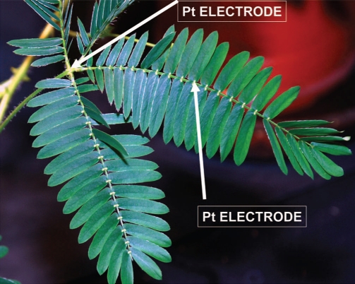
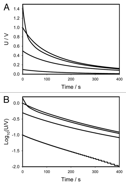
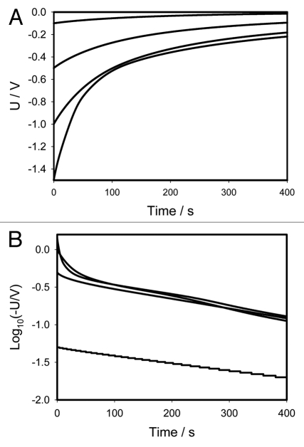
Figure 1 shows the location of Pt-electrodes in a pinna of Mimosa pudica. Figure 2A (+ in a secondary pulvinus and − in a rachis) and 3A (− in a secondary pulvinus and + in a rachis) show the time dependencies of a 47 mkF charged capacitor discharging in the pinna of Mimosa pudica when the polarity of the same electrodes was reversed. Figures 2B and 3B show the time dependencies of charged capacitors discharging in the Mimosa pudica in logarithmic coordinates.
Figure 1.
Location of electrodes in a pinna of Mimosa pudica.
Figure 2.
(A) Time dependence of electrical discharge in Mimosa pudica's pinna between electrodes connected to 47 µF charged capacitor (+ in a secondary pulvinus and − in a rachis) and an NI-PXI-4071 digital voltmeter. These results were reproduced 16 times. Location of Pt-electrodes is shown in Figure 1. (B) Time dependence of electrical discharge in the Mimosa pudica's pinna between electrodes in logarithmic coordinates. U is the capacitor voltage in volts.
Figure 3.
(A) Time dependence of electrical discharge in Mimosa pudica's pinna between electrodes connected to 47 µF charged capacitor (− in a secondary pulvinus and + in a rachis). Location of Pt-electrodes is shown in Figure 1. These results were reproduced 16 times. (B) Time dependence of electrical discharge in the Mimosa pudica's pinna between electrodes connected to charged capacitors in logarithmic coordinates. U is the capacitor voltage in volts.
If a capacitor of capacitance C is discharged during time t through a resistor R (Fig. 4A), the logarithm of capacitor voltage U is
| 1 |
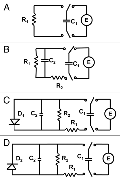
where U0 is the initial voltage of a capacitor and γ is the time constant. The circuit time constant γ = RC governs the discharging process. The voltage across the capacitor decreases exponentially from the initial value U0 to zero. As the capacitance or resistance increases the time of the capacitor discharge increases according to equation (1). Figures 2B and 3B show that if the initial voltage on a charged capacitor is below 1 V, the dependence of voltage on a capacitor is close to linear in logarithmic coordinates and can be described by the simple equivalent electrical scheme shown on Figure 4A or B. If the initial voltage on a charged capacitor is higher than 1 V (Figs. 2B and 3B) there is strong deviation from the linear dependence predicted by equation 1.
Figure 4.
Electrical equivalent schemes of a capacitor discharge in a plant tissue. Abbreviations: C1, charged capacitor from voltage source U; C2, capacitance of plant tissue; R, resistance in the Mimosa pudica tissue; D, diode.
Discussion
Electrical circuits in pinnae.
Figures 2 and 3 show that electrical discharge of a capacitor through the plant can be described in the first approximation as a discharge through a constant resistance at small potentials (Fig. 4A), though here, the better approximation can be achieved with the circuit in Figure 4B. At potentials higher than 0.5 V, the logarithmic plot in Figure 2A is definitely nonlinear meaning that the discharge can be described by the circuit in Figure 4B. The pattern of discharge strongly depends on polarity of the capacitor as can be seen in Figure 3. Here the departure from linear logarithmic dependence can be noticed much earlier, even at U <0.5 V. Each curve can be satisfactorily modeled with the electrical circuit in Figure 4B. However, parameters of this circuit would be different for different cases.
To illustrate this fact, the input resistance of the circuits was calculated.36 According to Ohm's law, this parameter is defined as voltage, U, divided by current, :
| 2 |
We found that in all cases presented in Figures 2 and 3 the discharge process could be perfectly approximated with doubleexponential function corresponding to the scheme in Figure 4B:
| 3 |
Here a and c are the amplitudes of exponential functions and b and d are the time constants. Substituting eq. (3) in eq. (2) we can find the input resistance:
| 4 |
The characteristic time in the very beginning of discharge is
| 5 |
The characteristic time in the beginning of the capacitor discharge depends on initial voltage as presented in Figure 5. Table 1 shows constants a, b, c and d for experimental dependencies presented in Figures 2 and 3.
Figure 5.
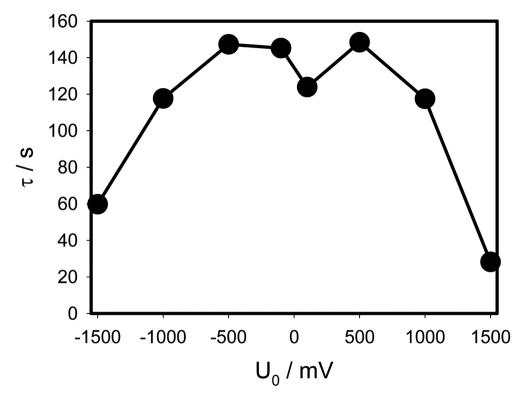
γ = RC dependence on the initial capacitor voltage during electrical discharge in Mimosa pudica's pinna between electrodes connected to charged capacitors. Location of Pt-electrodes is shown in Figure 1.
Table 1.
Parameters of double-exponential function in equation 3 for experimental dependencies presented in Figures 2 and 3
| Initial voltage U0 at 47 µF charged capacitor, V | a, V | b, s−1 | c, V | d, s−1 |
| 0.1 | 0.0122 | 0.0272 | 0.0874 | 0.0054 |
| 0.5 | 0.2280 | 0.0111 | 0.2660 | 0.0030 |
| 1.0 | 0.5476 | 0.0038 | 0.4460 | 0.0143 |
| 1.5 | 0.7702 | 0.0625 | 0.6763 | 0.0047 |
| −0.1 | −0.0812 | 0.0044 | −0.0185 | 0.0178 |
| −0.5 | −0.2382 | 0.0117 | −0.2568 | 0.0026 |
| −1.0 | −0.5007 | 0.0144 | −0.4927 | 0.0025 |
| −1.5 | −0.9197 | 0.0257 | −0.5762 | 0.0024 |
The curve in Figure 5 has a rough M-shape and is rather symmetrical with exception of the two middle points corresponding to the smallest voltages −0.1 V and +0.1 V. Here the dependence on polarity manifests itself in the strongest way. When the voltage is in the range from −1 V to +1 V, the characteristic time is between 120 and 150 seconds. At larger potentials the characteristic time sharply drops to 60 and even 30 seconds. That means that the plant's tissues are very electrically nonlinear which can be explained by the opening of various ion channels.
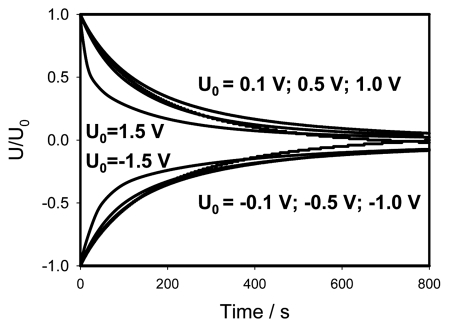
The non-linearity of electrical circuits in Mimosa pudica becomes especially obvious if data from Figures 2 and 3 are presented in normalized form by dividing the experimental curves by initial voltage (Fig. 6). If the applied initial potential U0 is less or equal to 1 V, all curves fall in the narrow strip where they practically coincide. That means that at small potentials the discharge is governed by the same electrical circuit that can be considered as a linear one (Fig. 4B). However at higher potentials the electrical circuit becomes strongly non-linear (Fig. 4C and D). The curves for U0 = ±1.5 V in Figure 6 strongly depart from the narrow strip corresponding to small voltages. Here the capacitor discharge is much faster, that can be explained by the opening of voltage gated channels and corresponding decrease of effective resistance.
Figure 6.
Normalized presentation of time dependence of electrical discharge in Mimosa pudica's pinna between electrodes connected to charged capacitor. U0 is the initial capacitor voltage in volts.
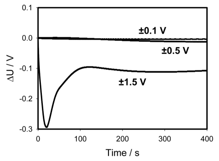
There is a strong rectification effect inside a pinna, which is sensitive to the polarity of the capacitor. It is illustrated in Figure 7, where the data from Figures 2 and 3 are presented as the sum of positive and negative charges. One can see that at small potentials the curves cancel each other—the sum goes close to zero. At U0 = ±1.5 V there is a strong difference between the curves demonstrating the dependence of rectification on polarity. Once again this can be caused by a redistribution of K+, Cl− and Ca2+ ions through ion channels in the pinna.19,20
Figure 7.
Time dependence of voltage differences (Figs. 2A and 3A) during electrical discharge in the Mimosa pudica's pinna between electrodes of different polarities connected to 47 mkF charged capacitor. Location of Pt-electrodes is shown in Figure 1.
It is convenient to represent electrochemical properties of biologically closed electrical circuits with idealized equivalent electrical circuit models consisting of discrete electrical components.37–39 The voltage gated K+ and Cl− ion channels in Mimosa pudica can be simulated by diodes (Fig. 4C and D). The equivalent electrical circuit in Figure 4C is similar to the electrical circuit in the midrib of Venus flytrap,24 which gives the same dependence of a capacitor discharge in a plant tissue.
Different polarity of the applied voltage can open different ion channels, such as K+ or Cl− ion channels and the equivalent electrical circuit can be simulated as shown in Figure 4C and D. These voltage gated ion channels were studied in detail a few years ago.18–20
The activation of biologically closed electrical circuits in Mimosa pudica can lead to different responses in plant tissue. A mechanical or electrical stimulus can induce electrical signals or action potentials, which propagate along the plasma membrane in phloem. Voltage-gated ionic channels control the plasma membrane potential and the movement of ions across membranes thereby regulating various biological functions.40 These biological nanodevices play vital roles in signal transduction in higher plants.15 Propagation of action potentials in Mimosa pudica along the pinna, petioles, pulvini and in the stem is documented in literature.6,16,18,36,41,42
Propagation of an action potential can induce a mechanical response by activating Cl− channels and voltage gated K+ ion channel in a pinna. Voltage gated K+ and Cl− ion channels can operate as an electrical starter of the osmotic motor in a pinna. Ion fluxes activate fast water transport through aquaporins43 between the lower half and upper half of the tertiary pulvinus or between outer and inner layers of pinnules following an electrical stimulus.
Processes associated with rapid movements of petioles and pinnae of sensitive plant Mimosa pudica have been attracting the attention of scientists since the Royal Society meeting1 on July 17, 1661. There are few hypotheses about the mechanism of the mechanisms underlying the Mimosa movements such as osmotic motors,8,44 muscular movements45 and actin phosphorylation,46 the chemical transmission hypothesis,5 electrical signal transduction,6 loss of turgor,4 but exact mechanism of this widely investigated phenomenon remains unknown.
Closing of pinnules and a petiole bending can be triggered by electrical discharge between electrodes in a pulvinus.35,36 Both voltage and transmitted charge are responsible for the electrostimulated plant movement. Kinetics of a petiole bending or pinnules closing by electrical or mechanical stimulation is identical. Electrochemical properties of pinnae, a pulvinus, secondary pulvinus and a petiole are different.6–8 The equivalent electrical circuit of a petiole was evaluated and described by mathematical model recently.36 In the present work we evaluated the simplest equivalent electrical circuit of a pinna by DC electrostimulation in vivo of Mimosa pudica's pinna using the new charged capacitor method.
Materials and Methods
Electrodes.
All measurements were conducted in the laboratory at 21°C inside a Faraday cage mounted on a vibration-stabilized table. Platinum electrodes were prepared from Teflon-coated platinum wires (A-M Systems, Inc., Sequim, WA). The response time of platinum electrodes was less than 0.1 µs, when we used square wave pulses from a function generator with the electrodes in the plant tissue. Insertion of the electrodes into Mimosa pudica caused the leaves to close, therefore each plant was allowed to rest for 3 hours until the leaves were completely relaxed and open. The time dependencies of the electrical discharge of the capacitor in Mimosa pudica were measured between 3 and 25 hours after insertion of the electrodes.
Data acquisition.
PCI eXtensions for Instrumentation (PXI) is a rugged PC-based platform that offers a high-performance solution for measurement and automation systems. PXI adds mechanical, electrical and software features that define complete systems for test, measurement and data acquisition. An NI-PXI-4071 digital multimeter (National Instruments, Austin, TX) connected to 0.1 mm thick Pt-electrodes was used to record the digital data.
Electrostimulation of cells clusters in vivo.
The Charge-Injection Method was used to precisely estimate the amount of electrical energy necessary to induce a response.33–36 A double pole-double throw (DPDT) switch was used to connect the 47 mkF capacitor to the PXI-4110 DC power supply (National Instruments) during charging and then to the plant during plant stimulation. By changing the switch position the charged capacitor can be instantaneously connected to the plant and induce a response. Since the charge of capacitor Q connected to the voltage source U is Q = CU, the amount of charge can be precisely regulated using different capacitors and applying various voltages.
Plants.
The seeds of Mimosa pudica L. were soaked in warm water (30°C) for 48 h. They were then grown in well drained peat moss at 21°C with a 12:12 hour light:dark photoperiod. After growing for two weeks the seedlings were transplanted into pots and placed in a plant growing chamber. Humidity averaged 45–50% and the plants were watered every day. Two to three month old plants were used for the experiments. Irradiance was 700–800 µE/m2s. All of the experiments were performed on healthy adult specimens.
Acknowledgements
This work was supported by the National Science Foundation (grant no. HRD0811507).
Abbreviations
- a, b, c, d
constants of double-exponential function
- C
capacitance
- DPDT
double pole double throw switch
- E
DC power supply
- PXI
PCI extensions for instrumentation
- R
resistance
- Rinput
input resistance
- τ
the circuit time constant
- t
time
- Q
charge of capacitor
- U
voltage
- U0
is the initial voltage of a capacitor
Footnotes
Previously published online: www.landesbioscience.com/journals/psb/article/11569
References
- 1.Hooke R. Micrographia. London: The Royal Society; 1667. [Google Scholar]
- 2.Gardiner W. On the power of contractility exhibited by the protoplasm of certain plant cells. Annals Botany. 1888;1:362–367. [Google Scholar]
- 3.Haberlandt G. Das reisleitende Gewebesystem der Sinnpflanse. Leipzig: Engelmann; 1890. (Ger). [Google Scholar]
- 4.Pfeffer W. The Physiology of Plants. Oxford: Clarendon Press; 1905. [Google Scholar]
- 5.Ricca U. Soluzione d'un problema di fisiologia. La propagazione di stimulo nella “Mimosa.”. Nuovo Giornale Botanico Italiano Nuovo Serie. 1916;23:51–170. (Ita). [Google Scholar]
- 6.Bose JC. Movements in Plants. Delhi: B.R. Publishing Corp; 1918. [Google Scholar]
- 7.Bose JC. The Nervous Mechanism of Plants. London: Longmans Green; 1926. [Google Scholar]
- 8.Bose JC. The Motor Mechanism of Plants. London: Longmans Green; 1928. [Google Scholar]
- 9.Trewavas A. What is plant behavior? Plant Cell Environment. 2009;32:606–616. doi: 10.1111/j.1365-3040.2009.01929.x. [DOI] [PubMed] [Google Scholar]
- 10.Bertholon M. De l'electricite des vegetaux: ouvrage dans lequel on traite de l'electricite de l'atmosphere sur les plantes, de ses effets sur leconomie des vegetaux, de leurs vertus medico. Paris: P.F. Didot Jeune; 1783. (Fre). [Google Scholar]
- 11.Ksenzhek OS, Volkov AG. Plant Energetics. San Diego: Academic Press; 1998. [Google Scholar]
- 12.Volkov AG. Green plants: Electrochemical interfaces. J Electroanal Chem. 2000;483:150–156. [Google Scholar]
- 13.Volkov AG. Electrophysiology and Phototropism. In: Balushka F, Manusco S, Volkman D, editors. Communication in Plants. Neuronal Aspects of Plant Life. Berlin: Springer; 2006. pp. 351–367. [Google Scholar]
- 14.Volkov AG, editor. Plant Electrophysiology. Berlin: Springer; 2006. [Google Scholar]
- 15.Volkov AG, Brown CL. Nanodevices in Nature. In: Kumar CSSR, editor. Nanodevices for Life Sciences. Weinheim: Wiley-VCH; 2006. pp. 440–463. [Google Scholar]
- 16.Fromm J, Lautner S. Electrical signals and their physiological significance in plants. Plant Cell Environm. 2007;30:249–257. doi: 10.1111/j.1365-3040.2006.01614.x. [DOI] [PubMed] [Google Scholar]
- 17.Sibaoka T. Excitable cells in Mimosa. Science. 1962;137:226. doi: 10.1126/science.137.3525.226. [DOI] [PubMed] [Google Scholar]
- 18.Abe T. Chloride ion efflux during an action potential in the main pulvinus of Mimosa pudica. Bot Mag. 1981;94:379–383. [Google Scholar]
- 19.Stoeckel H, Takeda K. Plasmalemmal, voltage-dependent ionic currents from excitable pulvinar motor cells of Mimosa pudica. J Membr Biol. 1993;131:179–192. doi: 10.1007/BF02260107. [DOI] [PubMed] [Google Scholar]
- 20.Stoeckel H, Takeda K. Calcium-sensitivity of plasmalemmal delayed rectifier potassium current suggests that calcium influx in pulvinar protoplasts from Mimosa pudica L. can be revealed by hyperpolarizion. J Membr Biol. 1995;146:201–209. doi: 10.1007/BF00238009. [DOI] [PubMed] [Google Scholar]
- 21.Volkov AG, Carrell H, Markin VS. Biologically closed electrical circuits in Venus flytrap. Plant Physiol. 2009;149:1661–1667. doi: 10.1104/pp.108.134536. [DOI] [PMC free article] [PubMed] [Google Scholar]
- 22.Volkov AG, Carrell H, Baldwin A, Markin VS. Electrical memory in Venus flytrap. Bioelectrochem. 2009;75:142–147. doi: 10.1016/j.bioelechem.2009.03.005. [DOI] [PubMed] [Google Scholar]
- 23.Evert DR. Factors affecting electrical impedance of intermodal stem sections. Plant Physiol. 1973;51:478–480. doi: 10.1104/pp.51.3.478. [DOI] [PMC free article] [PubMed] [Google Scholar]
- 24.Harker FR, Maindonald JH. Ripening of nectarine fruit. Changes in the cell wall, vacuole and membranes detected using electrical impedance measurements. Plant Physiol. 1994;106:165–171. doi: 10.1104/pp.106.1.165. [DOI] [PMC free article] [PubMed] [Google Scholar]
- 25.Inaba A, Manabe T, Tsuji H, Iwamoto T. Electrical impedance analysis of tissue properties associated with ethylene induction by electric currents in cucumber (Cucumis sativus L.) fruit. Plant Physiol. 1995;107:199–205. doi: 10.1104/pp.107.1.199. [DOI] [PMC free article] [PubMed] [Google Scholar]
- 25.Laarabi S, Kinani KE, Ettouhami A, Limouri M. In vivo impedance of the aerial organs of some mono- and dicotyledonous plants. Comptes Rendus Biol. 2005;328:253–262. doi: 10.1016/j.crvi.2004.11.006. [DOI] [PubMed] [Google Scholar]
- 26.McAdams ET, Jossinet J. Problems in equivalent circuit modeling of the electrical properties of biological tissues. Bioelectrochem Bioenerg. 1996;40:147–152. [Google Scholar]
- 27.Wang J, Zimmermann U, Benz R. Contribution of electrogenic ion transport to impedance of the algae Valonia utricularis and artificial membranes. Biophys J. 1994;67:1582–1593. doi: 10.1016/S0006-3495(94)80631-9. [DOI] [PMC free article] [PubMed] [Google Scholar]
- 28.Zatsepina GN, Tsaplev YuB. Nature of electrical polarity of a higher plant. Biophysics. 1980;5:147–150. [PubMed] [Google Scholar]
- 29.Zhang MIN, Willison JHM. Electrical impedance analysis in plant tissues: A double shell model. J Exp Bot. 1991;42:1465–1475. [Google Scholar]
- 30.Zhang MIN, Willison JHM. Electrical impedance analysis in plant tissues: Impedance measurements in leaves. J Exp Bot. 1993;44:1369–1375. [Google Scholar]
- 31.Zhang MIN, Willison JHM. Electrical impedance analysis in plant tissues: in vivo detection of freezing injury. Canadian J Bot. 1991;42:1465–1475. [Google Scholar]
- 32.Volkov AG, Adesina T, Markin VS, Jovanov E. Closing of Venus flytrap by electrical stimulation of motor cells. Plant Signal Behav. 2007;2:139–144. doi: 10.4161/psb.2.3.4217. [DOI] [PMC free article] [PubMed] [Google Scholar]
- 33.Volkov AG, Adesina T, Markin VS, Jovanov E. Kinetics and mechanism of Dionaea muscipula trap closing. Plant Physiol. 2008;146:694–702. doi: 10.1104/pp.107.108241. [DOI] [PMC free article] [PubMed] [Google Scholar]
- 34.Volkov AG, Coopwood KJ, Markin VS. Inhibition of the Dionaea muscipula Ellis trap closure by ion and water channels blockers and uncouplers. Plant Sci. 2008;175:642–649. [Google Scholar]
- 35.Volkov AG, Foster JC, Ashby TA, Walker RK, Johnson JJ, Markin VS. Mimosa pudica: Electrical and mechanical stimulation of plant movements. Plant Cell Environm. 2010;33:163–173. doi: 10.1111/j.1365-3040.2009.02066.x. [DOI] [PubMed] [Google Scholar]
- 36.Volkov AG, Foster JC, Markin VS. Signal transduction in Mimosa pudica: Biologically closed electrical circuits. Plant Cell Environm. 2010;33:816–827. doi: 10.1111/j.1365-3040.2009.02108.x. [DOI] [PubMed] [Google Scholar]
- 37.Grattarola M, Massobrio G. Bioelectronics Handbook. New York: McGraw-Hill; 1998. [Google Scholar]
- 38.Keener J, Sneyd J. Mathematical Physiology. New York: Springer; 2001. [Google Scholar]
- 39.Nagumo J, Arimoto S, Yoshizawa S. An active pulse transmission line simulating nerve axon. Proc IRE. 1962;50:1061–2070. [Google Scholar]
- 40.Volkov AG, Deamer DW, Tanelian DL, Markin VS. Liquid Interfaces in Chemistry and Biology. New York: Wiley; 1998. [Google Scholar]
- 41.Roblin G. Movements, bioelectrical events and proton excretion induced in the pulvini of Mimosa pudica L. by a period of darkness. Z Pflanzenphysiol. 1982;108:295–304. [Google Scholar]
- 42.Umrath K. Der Erregungsvorgang bei höheren Pflancen. Erg Biol. 1937;14:1–42. (Ger). [Google Scholar]
- 43.Tamiya T, Miyasaki T, Ishikawa H, Iruguchi N, Maki T, Matsumoto JJ, Tsuchiya T. Movement of water in conjunction with plant movement visualized by NMR imaging. J Biochem. 1988;104:5–8. doi: 10.1093/oxfordjournals.jbchem.a122421. [DOI] [PubMed] [Google Scholar]
- 44.Moran N. Osmoregulation of leaf motor cells. FEBS Lett. 2007;581:2337–2347. doi: 10.1016/j.febslet.2007.04.002. [DOI] [PubMed] [Google Scholar]
- 45.Balmer RT, Franks JG. Contractile characteristics of Mimosa pudica L. Plant Physiol. 1975;56:464–467. doi: 10.1104/pp.56.4.464. [DOI] [PMC free article] [PubMed] [Google Scholar]
- 46.Kameyama K, Kishi Y, Yoshomura M, Kanzawa N, Tsuchia T. Thyrosine phosphorylation in plant bending. Nature. 2000;407:37. doi: 10.1038/35024149. [DOI] [PubMed] [Google Scholar]


