Abstract
We report a new method for generating both continuous and discrete density gradients in microparticles of biodegradable polymers via an electrospray technique. The gradients were generated by spatially varying the deposition time of electrosprayed microparticles. The substrate coated with a density gradient of microparticles has varying surface roughness, offering a unique system for studying the effect of physical cues on neurite outgrowth from dorsal root ganglia. We obtained an optimal surface roughness for promoting neuron adhesion and neurite extension in vitro. Furthermore, this capability of approach was extended to generate a gradient of fluorescein isothiocyanate-labeled bovine serum albumin by encapsulating it in the polymer microparticles in situ during electrospray. Taken together, this new class of substrates with gradients of microparticle density can potentially be used in various biomedical applications such as neural tissue engineering.
1. Introduction
Physical (e.g., topographical) and chemical gradients have been demonstrated to play an important role in the development and regeneration of many biological tissues, including tendon enthesis,[1] dermis,[2] and peripheral nerve.[3] Accordingly, artificial substrates presenting one- and two-dimensional gradients of extracellular cues have attracted considerable attention in the field of biomedical research. A variety of strategies have been developed to incorporate physical and chemical gradients onto substrates or into matrices to be utilized in tissue engineering applications.[4,5] However, very few studies have demonstrated successful production of large-scale, topographical gradients with biological significance. Amis and coworkers demonstrated the fabrication of topographical gradients by varying nanoscale roughness of polymer films through temperature gradient annealing.[6] More recently, Spencer and coworkers developed an interesting method for fabricating material-independent topographical gradients.[7] The method involves a two-step process of particle erosion and chemical polishing, which may potentially be used for high-throughput diagnostic applications.
Alternatively, a topographical gradient can also be produced on the surface of a substrate via manipulation of micro- or nanoscale particles. Previous studies have demonstrated that a density gradient of metal nanoparticles could be formed through kinetically controlled adsorption of particles onto a functionalized substrate.[8-11] Specifically, a molecule gradient of amine groups (−NH2) was generated on the substrate by vapor deposition of NH2-terminated silane molecules. Gold nanoparticles were then attached to the NH2-functional groups by immersing the substrate in a gold colloid solution.[10] In another work, Spencer and coworkers prepared a density gradient of silica nanoparticles by dip-coating a positively charged ploy(ethylene imine) (PEI)-coated silicon wafer into a suspension of negatively charged silica nanoparticles.[11] Despite the success of these methods, their capability is somewhat limited due to the use of multiple procedures, time-consuming steps, and custom-made reagents or substrates. Therefore, a simple and effective method remains to be identified and developed for large-scale production of topographical gradients with micro- and nanoscale particles of biodegradable polymers.
Electrospray is a method with great potential for the fabrication of particle-based gradients. Electrospray is a process by which a liquid is forced through a capillary onto a collector while a potential drop on the order of kilovolts is applied between the capillary and the collector.[12-14] Electrospray in the single cone-jet mode provides a simple method for generating relatively uniform polymer particles with sizes ranging from hundreds of nanometers to tens of micrometers, which have previously been used as carriers for various chemotherapeutics, proteins, and other biomacromolecules.[12-15] Furthermore, unlike prior methods, the formation of microparticles using an electrospray process allows possible control of microparticle density and size. In the present work, we further extend the capability of electrospray to generate both continuous and discrete density gradients of biodegradable polymer microparticles on solid substrates through the use of a movable mask. Furthermore, the present study demonstrates the use of such a technique for generating protein gradients by loading the microparticles with the protein during the electrospray process.
2. Results and discussion
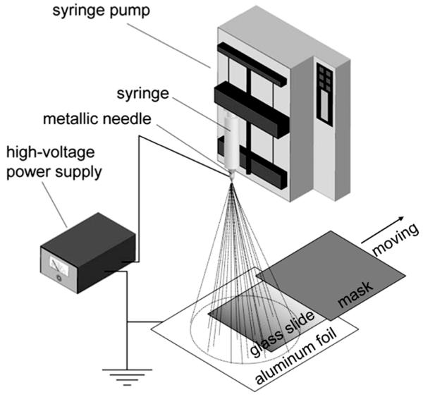
Figure 1 shows a schematic of the electrospray setup utilized to generate a graded coating of poly(lactic-co-glycolic acid) (PLGA) microparticles on a solid substrate (typically, a glass slide). Since the microparticles ejected from the nozzle are deposited randomly on the substrate and the density of particles is directly proportional to the deposition time, a gradient in particle density can be generated across the substrate by spatially varying the deposition time. In practice, a movable mask is introduced to control the time during which the substrate is exposed to the electrosprayed particles. Due to the presence of residual solvent, the particles can strongly adhere to the substrate without further treatment. The physical properties (e.g., conductivity, viscosity, and concentration) of the electrospray solution and operation parameters (e.g., the distance between nozzle and collector, applied electric potential, solution ejection rate, and moving speed of the mask) can all be adjusted to vary the resultant gradient profile.
Figure 1.
A schematic of the setup for generating a density gradient of PLGA microparticles on a glass slide via electrospray deposition. The mask above the substrate moves at a constant rate or stepped rates to vary the collection time from the left to the right side of the substrate.
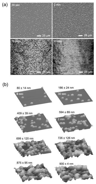
Figure 2a shows scanning electron microscopy (SEM) images of PLGA microparticles deposited on glass slides under different durations of time. Increase of deposition time resulted in a gradual increase in density of particles, and concomitant reduction in inter-particle separation. The average size of the deposited particles was approximately 3 μm. Clustering of particles appeared to become more significant as the deposition time increased, and it was particularly apparent for samples prepared with deposition times of 10 min or longer. As determined by atomic force microscopy (AFM, Figure 2b), the average roughness (or Ra value) was 80 ± 14, 186 ± 24, 409 ± 39, 594 ± 89, 699 ± 120, 726 ± 126, 875 ± 95, and 900 ± 4 nm for the samples prepared with a deposition time of 5 sec, 30 sec, 1 min, 2 min, 5 min, 10 min, 15 min, and 30 min, respectively. Note that the surface roughness was purely caused by the deposited particles since the substrates (i.e., glass slides) used for all the samples were more or less identical. The large deviations for some of the samples could be attributed to the formation of aggregates on the substrate with increasing deposition time. It is also feasible to observe a small deviation for the sample with a sufficiently long deposition time (e.g., 30 min) as the surface of the substrate could be completely covered by the microparticles.
Figure 2.
a) SEM and b) AFM images of PLGA microparticles deposited on glass slides with different collection times. The AFM scan was 25 μm × 25 μm. The surface roughness (root mean square value) was measured from 15 samples and reported as mean and standard deviation.
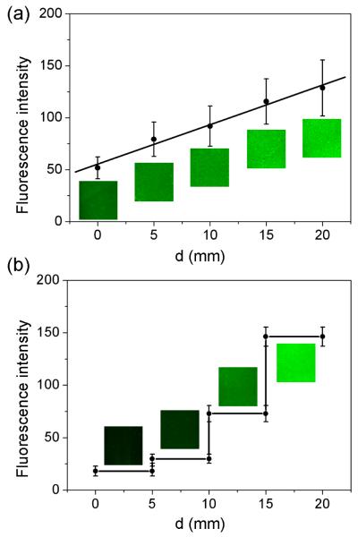
Besides topographic guidance, incorporation of a gradient of biochemical cues into a scaffold or matrix may represent a potent method of controlling tissue development and promoting repair in vitro and in vivo.[16-19] Previously, biomolecular gradients have been fabricated through the use of covalent chemical bonding,[20] electrostatic interaction,[21] diffusion,[22] microfluidics,[23] and micropatterning.[24] However, the capability of these methods is often limited due to the use of complicated procedures and/or the inability to achieve stable gradients of signal molecules. To fully demonstrate the capability and feasibility of the present approach, we have also fabricated a gradient of fluorescein isothiocyanate (FITC)-labeled bovine serum albumin (BSA) by loading PLGA microparticles with FITC-BSA in situ during the electrospray process.[12] Figure 3a shows fluorescence micrographs acquired from different locations of a sample with a continuous gradient in particle density. Figure 3b shows fluorescence micrographs acquired from different locations of another sample where the density of particles increased as a step function. In both cases, we observed an increase in fluorescence intensity along the gradient resulting from the increase in microparticle density. We used custom image processing software to quantify the variation in fluorescence intensity and obtained continuous (linear) and step gradients, respectively, for these two samples. The successful fabrication of both continuous and step gradients for the loaded fluorophor-conjugated BSA confirms that the electrospray technique, when combined with a movable mask placed over the collector, is a viable method for producing molecular/biomolecular gradient on the surface of a solid substrate. Furthermore, these observations confirm that electrospray is a technique capable of controlling the distribution and density of microparticles with good spatial resolution. In principle, electrospray can be employed to generate customized molecular gradients with a wide variety of hydrophilic or hydrophobic payloads.
Figure 3.
Fluorescence micrographs and intensity plots as a function of d along the direction of gradient for FITC-BSA-encapsulated PLGA microparticles: a) a continuous gradient and b) a step-function gradient. The parameter d refers to the distance away from the edge of the substrate having the lowest particle density.
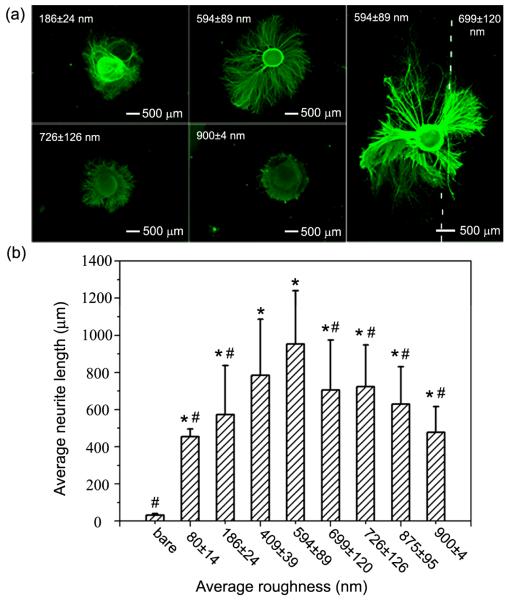
Surface roughness has been demonstrated to dramatically affect adhesion, proliferation and differentiation of multiple cell types, including osteoblasts,[25] and fibroblasts,[26] among others. However, previous studies of neuronal responses to substrates with varying surface topography have been limited in terms of gradation. Specifically, the majority of studies investigating the effect of surface roughness on neuronal activity has focused on the use of anisotropic substrates containing, for example, microgrooves.[27] The use of anisotropic substrates in prior studies has raised questions as to whether neurons respond directly to surface roughness or to the specific size and shape of features presented on the culture substrate. The present system provides a good model to single out the effect of surface roughness on neurite outgrowth from cultured primary neurons. Specifically, we measured neurite outgrowth from embryonic chick (E8) dorsal root ganglia (DRG) across isotropic substrates coated with PLGA microparticles in varying densities. The effect of discrete gradients of PLGA microparticles was also investigated by measuring neurite outgrowth from DRG cultured on the boundaries between regions of different particle densities. Figure 4a (left and middle column) shows fluorescence micrographs of typical neurite fields extending from DRG cultured on substrates coated with different densities of PLGA microparticles for 6 days. The microparticle-coated substrates were post-modified with laminin, an extracellular matrix protein present in neural basal lamina, to facilitate neurite adhesion and outgrowth.[28-30]
Figure 4.
a) Fluorescence micrographs of typical neurite fields of DRG cultured on PLGA microparticles prepared with different collection times and then coated with laminin. b) Average neurite lengths as a function of surface roughness (root mean square value), which was measured from 15 samples and reported as mean and standard deviation. The *, # indicate statistically significant differences from the bare substrate and the substrate with Ra value of 594 ± 89 nm, respectively (p < 0.05, one-way ANOVA, LSD post hoc test).
Our results demonstrated that surface roughness, as dictated by microparticle density, had a distinctive influence on neurite outgrowth. Both bare substrates and substrates presenting low densities of microparticles (with Ra values of 80 ± 14 nm and 186 ± 24 nm) failed to facilitate DRG adhesion and neurite extension. DRG that were able to adhere to surfaces with low densities of microparticles expressed very few neurites that were relatively short. In contrast, substrates presenting higher densities of microparticles and, therefore, greater surface roughness (with Ra values of 409 ± 39 nm, 594 ± 89 nm, 699 ± 120 nm, and 726 ± 126 nm), greatly facilitated the adhesion of cultured DRG and enhanced neurite outgrowth. Neurites extending from DRG adhered to substrates with moderate Ra values were notably longer than neurites extending from DRG cultured on substrates with lower surface roughness (Ra values of 80 ± 14 nm and 186 ± 24 nm). Furthermore, surfaces presenting greater densities of microparticles and, therefore, greater Ra values (875 ± 95 nm and 900 ± 4 nm) promoted DRG adhesion but reduced neurite extension when compared to surface presenting moderate microparticle densities. Neurites extending from DRG adhered to surfaces presenting high densities of microparticles were also shorter and exhibited a tortuous morphology. These results agree with previous reports that examined the effect of nanoscale surface roughness on neuron adhesion and viability. Cui and co-workers demonstrated that cells from substantia nigra could adhere well and survive for 5 days on silicon surface with an average roughness ranging from 20 to 50 nm, while cells showed poor adhesion on surfaces with average roughness less than 10 nm or greater than 70 nm.[31] In a separate study, Newaz and co-workers found that adhesion of primary cortical neurons increased with increasing surface roughness from 0 to 64 nm, and decreased at roughness of 204 nm or more,[32] confirming that excessively low or high surface roughness negatively affected cell attachment. Hence, our results are consistent with previous studies that were built upon a variety of substrates with varying degrees of surface roughness. Such correlation demonstrates that this effect is independent of material type, and more importantly, represents a unique behavioral response of individual neurons to extracellular features. Moreover, it appears that an optimal surface roughness seems to exist for both neuron adhesion and neurite extension.
Neurite extension was also examined from DRG cultured on the interface between regions of varying microparticle densities, specifically with Ra values of 594 ± 89 nm and 699 ± 89 nm (see the right column of Figure 4a). In this case, the neurites were found to extend over a longer distance on the region with a moderate microparticle density (Ra: 594 ± 89 nm) than those on the region with a high microparticle density (Ra: 699 ± 89 nm). Observations of different neurite elongation at the interface of regions of varying microparticle densities were consistent with what was observed for separate samples, confirming that surfaces with various particle densities indeed had differential effects on neurite outgrowth.
We quantified the average neurite length using custom image processing software designed using MATLAB. Figure 4b shows that the average neurite length increased as surface roughness was increased from low to moderate and subsequently decreased as surface roughness further increased from moderate to high. The average neurite length was greatest on substrates with a surface roughness Ra value of 594 ± 89 nm (average neurite length: 954 ± 286 μm), which was about 30 times and 2 times greater than what was measured for samples on bare substrates (average neurite length: 32 ± 8 μm) and substrates with a surface roughness Ra value of 900 ± 4 nm (average neurite length: 478 ± 138 μm), respectively. Statistical analysis revealed significant differences between average neurite lengths measured for the substrates with moderate surface roughness Ra value of 594 ± 89 nm and bare substrates, as well as for substrates with surface roughness Ra values of 80 ± 14, 186 ± 24, 699 ± 120, 726 ± 126, 875 ± 95, and 900 ± 4 nm (p < 0.05). Together, these results suggest that an optimal microparticle density, and therefore optimal surface roughness (Ra value of 594 ± 89 nm), exists at which DRG adhesion and neurite extension were both maximized. Observation of a parabolic relationship between surface roughness and neurite activity suggests that moderate surface roughness provided a favorable number of adhesion sites permissive to neurite adhesion and extension, while lower or higher surface roughness were not favorable for either neurite adhesion or outgrowth.
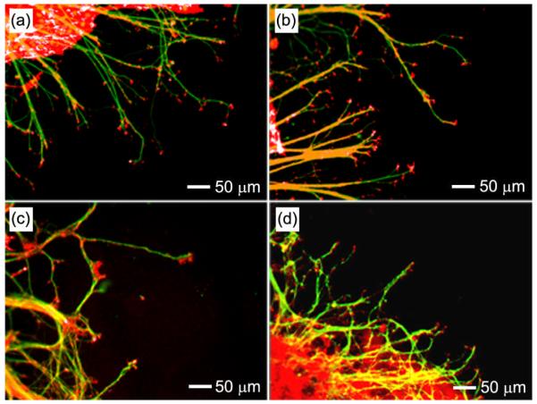
In order to understand how the microparticle-coated surface modulated neurite outgrowth, we examined filopodia in axonal growth cones of extending neurites via F-actin staining. As shown in Figure 5, filopodia were longer and appeared more frequently along neurites extending on substrates with moderate roughness relative to those extending on substrates with greater surface roughness. This observation suggests that extending neurites formed more aptly focal adhesions to a surface of moderate roughness, a condition required for further neurite extension and elongation. While these results demonstrate that neurite outgrowth was dramatically influenced by surface roughness, during which high surface roughness impeded neurite extension, prior research has not been able to reach a clear consensus as to how an extending neurite interacts with such a surface feature.
Figure 5.
Fluorescence micrographs showing the neurofilament (green) and F-actin (red) of neurites extending from DRG cultured on substrates pre-coated with PLGA microparticles for different periods of time by electrospray. The Ra values of the substrates were a) 409 ± 39 nm, b) 594 ± 89 nm, c) 726 ± 126 nm, and d) 900 ± 4 nm, respectively.
Prior research has shown that growth cones, particularly the filopodia and lamellipodia, play a key role in axonal guidance and elongation.[33,34] Neurite extension occurs when filopodia and lamellipodia, structures supported by actin filaments and dynamic microtubules, are stabilized, allowing for the new process of spreading of neurites.[35] Recent reports demonstrate that cell soma are capable of adapting to a surface with suitable roughness, therefore maximizing the contact area between the cellular membrane and the material and facilitating cell adhesion and spreading.[32] Yet, additional studies have shown that actin filaments and microtubules within the cytoplasm are too rigid to allow considerable deformation of filopodia to accommodate notable alterations of topography.[36-38] Based on this information, it can be hypothesized that surface roughness may influence focal adhesion formation and therefore cytoskeletal tension and neurite elongation. Specifically, neurites extending on substrates with low or moderate surface roughness may utilize adjacent surface features as points of adhesion, resulting in neurite elongation with little structural disruption for the extending axons. In contrast, neurites cultured on substrates with high surface roughness, while flooded with many available points of adhesion, are required to make short, tight, multi-directional turns in order to navigate across the tortuous surface. Yet, comparison to prior studies demonstrating neurite elongation across surfaces presenting extreme surface topographies (e.g., perpendicular microgrooves) suggests that the behavior observed in the present work seems to fit any one of the following two modes by which neurites navigate through complex physical environments. The first mode, represented in studies of microgrooved surfaces, may involve neurites crossing over regions of complex topography due to their preference to grow straight.[39] This response to dramatic topographical features may originate from the inability of the neurite to undergo cytoskeletal bending required to accommodate topographic changes. Such a scenario could correspond to the surface with a low or moderate roughness. The second mode, demonstrated in the present study, may involve frustrated circumnavigation of the complex topography, and turning up and down the microparticles gently, necessitating long period growth cone pathfinding. This case could coincide with the surface with a high roughness. While mechanistically distinct, both proposed modes of elongation would require excess expenditure of cellular resources and energy, eventually resulting in reduced rates of neurite extension.
3. Conclusions
In summary, we have demonstrated a new single-step method for generating continuous and discrete density gradients of PLGA microparticles on solid substrates via electrospray by spatially controlling the collection time. The density of particles was found to increase as the collection time was prolonged, providing a simple method for the generation of a surface with graded surface roughness. The present work also demonstrates an optimal surface roughness for promoting neurite adhesion and extension in vitro. These findings provide further insight into both the interaction between neurites and biomaterial scaffolds, as well as physical cues present within the human nervous system that may influence axonal guidance and regeneration in vivo. Furthermore, the present work demonstrates the capability of electrospray as a technique in generating continuous and discrete gradients of biodegradable microparticles loaded with a specific biomolecular agent. Together, these results suggest that the density gradients of microparticles formed through electrospray may provide a new platform for both therapeutic and investigational applications.
4. Experimental
Deposition of PLGA microparticles with a gradient in density
Both pristine and PLGA particles loaded with FITC-BSA were utilized to form density gradients using an electrospray technique, where the setup was similar to what was used previously for electrospinning.[40-44] To create a FITC-BSA gradient, FITC-BSA (Sigma-Aldrich, St. Louis, MO) solution in phosphate buffer saline (PBS) buffer (Invitrogen, Carlsbad, CA) was added to a solution of dichloromethane (DCM) (Fisher Chemical, Waltham, MA) containing 8% (w/v) PLGA (40,000-75,000 molecular weight, lactide/glycolide = 50:50, Sigma-Aldrich) and 10% (w/w) pluronic F127 (Sigma-Aldrich) to form an emulsion containing PLGA and FITC-BSA. This emulsion or a solution of 8% (w/v) PLGA in N, N-dimethylformamide (DMF) (Fisher Chemical, Waltham, MA) was loaded into a 5 mL plastic syringe with a 24-gauge needle attached, and dispensed using a syringe pump at an injection rate of 0.5 mL/h. Glass slides were cleaned using ethanol and placed on a piece of aluminum foil to serve as the collector. A moveable paper mask was connected to a second syringe pump and placed 1 cm above the glass slide during electrospray.
The microparticle-coated substrates were sterilized in 70% ethanol overnight, and washed with PBS buffer three times. Samples undergoing laminin coating were immersed in a 0.1% poly-L-lysine (PLL) (Sigma-Aldrich) solution for 1 h at room temperature, and washed with PBS buffer three times. Finally, the samples were immersed in a laminin solution (26 μL, 50 μg/mL laminin solution diluted with 5 mL of PBS buffer) (Sigma-Aldrich) at 4 °C overnight. Prior to DRG seeding, the sample was rinsed with PBS buffer three times.
Characterization of the graded coatings of PLGA microparticles
The coatings of PLGA microparticles prepared under various collection times were characterized using a scanning electron microscope (SEM) (200 NanoLab, FEI, Hillsboro, OR). Prior to imaging, the samples were coated with platinum for 30 s using a sputter at a current intensity of 40 mA. The surface topography and roughness of the coatings were analyzed using a tapping-mode atomic force microscope (AFM) (Nanoman, Veeco, Santa Barbara, CA).
Dorsal root ganglia (DRG) culture
Embryonic day 8 chicks (E8, stage HH35-36) were removed from the eggs and decapitated. DRG were dissected from the thoracic region and collected in Hank’s buffered salt solution (HBSS) prior to plating. DRG were seeded on substrates of varying roughness (1 DRG per sample) and incubated for 6 days in modified neurobasal (NB) media containing 1% ABAM, 1% N-2 supplement (Invitrogen), and 30 ng/mL Beta nerve growth factors (NGF) (R&D Systems, Minneapolis, MN).
Dorsal root ganglia immunostaining
After incubation for 6 days, the DRG were immunostained with the marker anti-neurofilament 200 (Sigma-Aldrich). Briefly, the DRG were fixed in 3.7% formaldehyde for 45 min and permeabilized by 0.1% Triton X-100 for 30 min. The samples were blocked in PBS containing 2.5% bovine serum albumin (BSA) (Sigma-Aldrich) for 1 h. Anti-NF 200 diluted with PBS containing1.5% BSA was applied to the cells overnight at 4 °C. A secondary antibody, AlexaFluor 488 goat anti-mouse IgG (1:200, Invitrogen), was then applied for 1 h at room temperature. After staining, fluorescence images were captured using a QICAM Fast Cooled Mono 12-bit camera (Q Imaging) attached to an Olympus microscope with Capture 2.90.1 (Olympus). The average length of the extended neurites was subsequently calculated from the fluorescence images using custom-designed image processing software constructed from MATLAB (MathWorks). Statistical analysis of average neurite length was performed for each group in the between-subject design (ANOVA). Post-hoc multiple comparison analysis was done using LSD test, and significance levels were taken to be p < 0.05.
Footnotes
This work was supported in part by a 2006 NIH Director’s Pioneer Award (DP1 OD000798) and startup funds from Washington University in St. Louis. This work was performed in part at the Nano Research Facility (NRF), a member of the National Nanotechnology Infrastructure Network (NNIN), which is supported by the National Science Foundation under award no. ECS-0335765. XL is a visiting student from Tianjin University and was also partially supported by the China Scholarship Council.
Contributor Information
Xiaoran Li, Department of Biomedical Engineering, Washington University, St. Louis, MO 63130 (USA); School of Materials Science and Engineering, Tianjin Key Laboratory of Composite and Functional Materials, Tianjin University, Tianjin 300072 (P. R. China).
Matthew R. MacEwan, Department of Biomedical Engineering, Washington University, St. Louis, MO 63130 (USA)
Jingwei Xie, Dr., Department of Biomedical Engineering, Washington University, St. Louis, MO 63130 (USA)
Daku Siewe, Department of Biomedical Engineering, Washington University, St. Louis, MO 63130 (USA).
Xiaoyan Yuan, School of Materials Science and Engineering, Tianjin Key Laboratory of Composite and Functional Materials, Tianjin University, Tianjin 300072 (P. R. China)
Younan Xia, Department of Biomedical Engineering, Washington University, St. Louis, MO 63130 (USA).
References
- [1].Thomopoulos S, Williams GR, Soslowsky LJ. J. Biomech. Eng. 2003;125:106. doi: 10.1115/1.1536660. [DOI] [PubMed] [Google Scholar]
- [2].Gurtner GC, Werner S, Barrandon Y, Longaker MT. Nature. 2008;453:314. doi: 10.1038/nature07039. [DOI] [PubMed] [Google Scholar]
- [3].Cao X, Shoichet MS. Neuroscience. 2001;103:831. doi: 10.1016/s0306-4522(01)00029-x. [DOI] [PubMed] [Google Scholar]
- [4].Singh M, Berkland C, Detamore M. Tissue Eng. Part B. 2008;14:341. doi: 10.1089/ten.teb.2008.0304. [DOI] [PMC free article] [PubMed] [Google Scholar]
- [5].Li X, Xie J, Lipner J, Yuan X, Thomopoulos S, Xia Y. Nano lett. 2009;9:2763. doi: 10.1021/nl901582f. [DOI] [PMC free article] [PubMed] [Google Scholar]
- [6].Washburn NR, Yamada KM, S. CG, Jr., Kennedy SB, Amis EJ. Biomaterials. 2004;25:1215. doi: 10.1016/j.biomaterials.2003.08.043. [DOI] [PubMed] [Google Scholar]
- [7].kunzler TP, Drobek T, Sprecher CM, Schuler M, Spencer ND. Appl. Surf. Sci. 2006;253:2148. [Google Scholar]
- [8].Kramer S, Xie H, Gaff J, Williamson J, Tkachenko A, Nouri N, Feldeim D, Feldheim D. J. Am. Chem. Soc. 2004;126:5388. doi: 10.1021/ja031674n. [DOI] [PubMed] [Google Scholar]
- [9].Kunzler TP, Huwiler C, Drobek T, Voros J, Spencer ND. Biomaterials. 2007;28:5000. doi: 10.1016/j.biomaterials.2007.08.009. [DOI] [PubMed] [Google Scholar]
- [10].Bhat RR, Fischer DA, Genzer J. Langmuir. 2002;8:5640. [Google Scholar]
- [11].Huwiler C, Kunzler T, Textor M, Vorros J, Spencer N. Langmuir. 2007;23:5929. doi: 10.1021/la0700422. [DOI] [PubMed] [Google Scholar]
- [12].Xie J, Wang CH. Biotechnol. Bioeng. 2007;97:1278. doi: 10.1002/bit.21334. [DOI] [PubMed] [Google Scholar]
- [13].Xie J, Tan RS, Wang CH. J. Biomed. Mater. Res. 2008;85(A):897. doi: 10.1002/jbm.a.31499. [DOI] [PubMed] [Google Scholar]
- [14].Xie J, Marijnissen J, Wang CH. Biomaterials. 2006;27:3321. doi: 10.1016/j.biomaterials.2006.01.034. [DOI] [PubMed] [Google Scholar]
- [15].Xu Y, Hanna M. Int. J. Pharm. 2006;320:30. doi: 10.1016/j.ijpharm.2006.03.046. [DOI] [PubMed] [Google Scholar]
- [16].Barkefors I, Jan SL, Jakobsson L, Hejll E, Carlson G, Johansson H, Jarvius J, Park JW, Jeon NL, Kreuger J. J. Biol. Chem. 2008;283:13905. doi: 10.1074/jbc.M704917200. [DOI] [PubMed] [Google Scholar]
- [17].Stefonek T, Masters K. Wound Rep. Reg. 2007;15:847. doi: 10.1111/j.1524-475X.2007.00288.x. [DOI] [PubMed] [Google Scholar]
- [18].Phillips JE, Burns KL, Doux JML, Guldberg RE, Garcìa AJ. Proc. Natl. Acad. Sci. U.S.A. 2008;105:12170. doi: 10.1073/pnas.0801988105. [DOI] [PMC free article] [PubMed] [Google Scholar]
- [19].Kapur T, Shoichet M. J. Biomed. Mater. Res. 2004;68A:235. doi: 10.1002/jbm.a.10168. [DOI] [PubMed] [Google Scholar]
- [20].DeLong SA, Moon JJ, West JL. Biomaterials. 2005;26:3227. doi: 10.1016/j.biomaterials.2004.09.021. [DOI] [PubMed] [Google Scholar]
- [21].Miao Y, Helseth L. Colloids Surf. B Biointerfaces. 2008;66:299. doi: 10.1016/j.colsurfb.2008.07.002. [DOI] [PubMed] [Google Scholar]
- [22].Peret B, Murohy W. Adv. Funct. Mater. 2008;18:3410. doi: 10.1002/adfm.200800218. [DOI] [PMC free article] [PubMed] [Google Scholar]
- [23].Li GN, Liu J, Hoffman-Kim D. Ann. Biomed. Eng. 2008;36:889. doi: 10.1007/s10439-008-9486-z. [DOI] [PubMed] [Google Scholar]
- [24].Rosoff W, Urbach J, Esrick M, McAllister R, Richards L, Goodhill G. Nat. Neurosci. 2004;7:678. doi: 10.1038/nn1259. [DOI] [PubMed] [Google Scholar]
- [25].Price R, Ellison K, Haberstroh KM, Webster TJ. J. Biomed. Mater. Res. 2004;70A:129. doi: 10.1002/jbm.a.30073. [DOI] [PubMed] [Google Scholar]
- [26].Kunzler TP, Drobek T, Schuler M, Spencer ND. Biomaterials. 2007;28:2175. doi: 10.1016/j.biomaterials.2007.01.019. [DOI] [PubMed] [Google Scholar]
- [27].Walsh JF, Manwaring ME, Tersco PA. Tissue Eng. 2005;11:1085. doi: 10.1089/ten.2005.11.1085. [DOI] [PubMed] [Google Scholar]
- [28].Xie J, MacEwan M, Willerth S, Li X, Moran D, Sakiyama-Elbert S, Xia Y. Adv. Funct. Mater. 2009;19:2312. doi: 10.1002/adfm.200801904. [DOI] [PMC free article] [PubMed] [Google Scholar]
- [29].Xie J, MacEwan M, Li X, Sakiyama-Elbert S, Xia Y. ACS Nano. 2009;3:1151. doi: 10.1021/nn900070z. [DOI] [PMC free article] [PubMed] [Google Scholar]
- [30].Arimura N, Kaibuchi K. Nat. Rev. Neurosci. 2007;8:194. doi: 10.1038/nrn2056. [DOI] [PubMed] [Google Scholar]
- [31].Fan YW, Cui FZ, Hou SP, Xu QY, Chen LN, Lee I-S. J. Neurosci. Methods. 2002;120:17. doi: 10.1016/s0165-0270(02)00181-4. [DOI] [PubMed] [Google Scholar]
- [32].Khan SP, Auner GG, Newaz GM. Nanomed. Nanotechnol. Biol. Med. 2005;1:125. doi: 10.1016/j.nano.2005.03.007. [DOI] [PubMed] [Google Scholar]
- [33].Gallo G, Letourneau PC. Curr. Biol. 2002;12:R560. doi: 10.1016/s0960-9822(02)01054-0. [DOI] [PubMed] [Google Scholar]
- [34].Mattila PK, Lappalainen P. Nat. Rev. Mol. Cell Biol. 2008;9:446. doi: 10.1038/nrm2406. [DOI] [PubMed] [Google Scholar]
- [35].Mueller BK. Annu. Rev. Neurosci. 1999;22:351. doi: 10.1146/annurev.neuro.22.1.351. [DOI] [PubMed] [Google Scholar]
- [36].Dunn GA, Heath JP. Exp. Cell. Res. 1976;101:1. doi: 10.1016/0014-4827(76)90405-5. [DOI] [PubMed] [Google Scholar]
- [37].Smeal RM, Tresco PA. Exp. Neurol. 2008;213:281. doi: 10.1016/j.expneurol.2008.05.026. [DOI] [PubMed] [Google Scholar]
- [38].Smeal RM, Rabbitt R, Biran R, Tresco PA. Ann. Biomed. Eng. 2005;33:376. doi: 10.1007/s10439-005-1740-z. [DOI] [PubMed] [Google Scholar]
- [39].Li N, Folch A. Exp. Cell Res. 2005;311:307. doi: 10.1016/j.yexcr.2005.10.007. [DOI] [PMC free article] [PubMed] [Google Scholar]
- [40].Li D, Xia Y. Adv. Mater. 2004;16:1151. [Google Scholar]
- [41].Li D, Xia Y. Nano Lett. 2004;4:933. [Google Scholar]
- [42].Li D, Wang Y, Xia Y. Nano Lett. 2003;3:1167. [Google Scholar]
- [43].Li D, Wang Y, Xia Y. Adv. Mater. 2004;16:361. [Google Scholar]
- [44].Li D, Gong O, McCann JT, Xia Y. Nano Lett. 2005;5:913. doi: 10.1021/nl0504235. [DOI] [PubMed] [Google Scholar]


