

Abstract
A novel, miniaturized, high-efficiency photocatalytic cell, able to work in dynamic conditions, has been designed and validated in this study. Microfluidic channels were molded out of polydimethylsiloxane (PDMS) by means of standard soft lithography techniques, so as to work as photocatalytic cells, where the coupling of anatase titanium dioxide thin films and platinum electrodes, allows an electrically assisted photocatalytic reaction to produce dissolved oxygen gas from the water content of flowing fluid (e.g. blood). The thin films were deposited onto quartz glass substrates at room temperature (300K) using reactive radio-frequency sputtering with a titanium metal target. The photocatalytic activity was evaluated through reduction rate of methylene blue solution. The results of the current study, as a proof of concept, have shown that the device can generate oxygen at a rate of 4.06μM O2/(cm2 min), thus extending its possible application range to the full oxygenation of flowing venous blood.
Introduction
The breakthrough work of Fujishima and Honda in 19721, in which they achieved ultraviolet light-induced water cleavage with the use of titanium dioxide (TiO2) in an electrochemical cell, has drawn considerable attention in recent years to the “acceleration of a photoreaction by the presence of a catalyst”2 or photocatalysis. Photocatalysts work by the following principle: the material absorbs energy from photoexcitation, leading to the creation and separation of electrons and holes. Such a charge separation can generate electrical work through an external load or can be used to drive chemical (redox) reactions3. Research on photocatalysis has explored the decomposition of organic pollutants and microorganisms, the superhydrophilic self-cleaning properties of surfaces, and the photosplitting of water, among other applications. Semiconductors can act as photocatalysts because of their electronic structure and TiO2, in particular, has been a popular choice. It is non-toxic and mechanically stable, can be fabricated at low-cost, and the anatase phase of TiO2 has a bandgap of approximately 3.2 eV, ideal for excitation by light in the ultraviolet range.
Since the photocatalytic activity of TiO2 is influenced by the crystal size, crystal structure, crystallinity, and surface hydroxylation, the synthesis of phase pure nanocrystalline anatase TiO2 is challenging4. The most commonly tested compounds for decomposition through the photocatalysis are phenols, chlorophenols, pesticides, herbicides, benzenes, alcohols, dyes, pharmaceutics, humic acids, organic acids, and others.
In the last few years, researchers have been investigating the effects the photocatalytic activity of TiO2 has on blood5–8. In particular, blood oxygenation can be obtained by splitting water molecules contained in plasma and thus allowing the combination of O2 with hemoglobin molecules. In a previous work6, a photocatalytic cell (PC) was developed, which was able to oxygenate bovine blood. More recently, a simpler PC was designed and used with human blood8, even if the oxygenation was reached in static conditions.
Based on the idea of overcoming the previous limitations of blood oxygenation, we present in this work the development of a novel miniaturized PC able to operate on a flowing medium. The cell is made of biocompatible materials, thus making it possible to extend its application range to blood oxygenation. A pure anatase TiO2 thin film was obtained, and its photocatalytic activity was evaluated by degradation tests of methylene blue dye (MB) in aqueous dissolution. Finally, a tests on bovine blood were carried out to evaluate the performance of the PC in terms of oxygenation rate.
Methods
2.1 Photocatalytic cell (PC) design
The photocatalytic cell is composed of (1) a microfluidic channel molded out of polydimethylsiloxane (PDMS); (2) a platinum (Pt) electrode that is exposed to the liquid flowing through the channel and by means of which a bias potential can be maintained; and (3) an anatase TiO2 thin film deposited onto a conducting indium tin oxide (ITO) thin film to form a semiconducting TiO2/ITO junction.
A bias potential can be maintained across the height of the channel by means of the Pt electrode, deposited as thin film onto the PDMS that constitutes the top of the channel, and the ITO film that is beneath the TiO2. In Figure 1 a schematic representation of the functioning mechanism of the PC is sketched, showing electrodes, the path of the flowing liquid and the ultraviolet (UV) light source. The photocatalytic reaction takes place in the flowing liquid within a microchamber, whose design relies on a thin rectangular cross-sectioned channel (4.5mm wide × 25mm long × 0.1mm high). Studies have found that the photocatalytic efficiency can be increased by creating ITO/TiO2 junction8. An applied bias voltage across the ITO/TiO2 junction enhances the migration of the electron/hole pairs to the surface of the TiO2 film where further oxidation of water can take place. The bias voltage also conducts away the electrons generated when the TiO2 film is irradiated by UV light and minimizes the recombination process of electron and holes that can slow down the photocatalytic reaction9–11.
Figure 1.
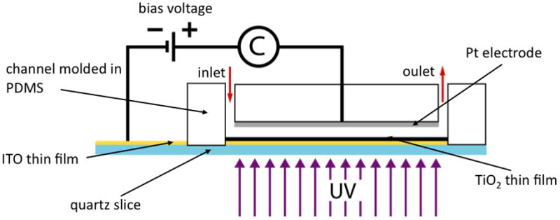
Schematic representation of the photocatalytic cell system. A PDMS microchannel, where liquid flows through input and output ports, is bonded on a pretreated quartz slice. An ITO/TiO2 junction is in fact deposited on the quartz surface. The top wall of the channel is covered by a Pt electrode, connected directly to the ITO layer, thus closing an electrical circuit.
2.2 PC development
Side-walls: PDMS microchannel
The microchannel was molded in PDMS using established soft lithography methods 12. Silicon molds containing the outlines of the channel in positive relief were fabricated by spinning negative photoresist (SU8-50; MicroChem) at 1000rpm for 60s onto silicon wafers followed by exposure to UV-radiation through a transparency mask printed with the channel outlines. The molds were pretreated with a silanizing agent (chloro-trimethyl-silane, Aldrich), and PDMS (Sylgard 184, Dow Corning) (10:1 ratio of elastomer to curing agent) was spun 60 seconds at 1110rpm onto them up to a thickness of 100μm.
After curing for 3 hours at 80°C, the solidified PDMS within the channel region was peeled away to create a void through which the fluid can flow. Figure 2A shows the steps required to obtain the 100μm layer.
Figure 2.

Microfabrication process developed to realize the PDMS microchannel (A) and the patterned Pt electrode (B). The mask, in which only the patterns borders are drawn, (i) is brought into soft contact with the wafer covered with a 100 μm film of SU-8 resist (ii); the photoresist is exposed and developed to reveal the channel outline (iii); a 100 μm thick layer of PDMS is spun onto the wafer and cured (iv); and the PDMS in the channel region is peeled away (v). A 5mm thick layer of PDMS cured overnight (vi) is masked with a thinner PDMS layer (vii) and placed in a RF sputterer for Ti/Pt deposition (viii). After mask removal, a T-shaped Pt electrode is patterned (ix).
Top layer: Pt electrode
In order to apply a bias voltage across the ITO/TiO2 junction, a Pt electrode (25mm × 4.5mm) was created on the top wall of the microchannel. This patterned electrode is exposed to the flowing fluid and therefore has the same length and width as the channel. To fabricate the electrode layer, pieces of PDMS (25mm wide × 35mm long × 5mm thick) were prepared using elastomer and curing agent mixed to a ratio of 5:1, respectively, and baked overnight at 80°C. This block served as substrates for the metal deposition, during which further thin PDMS layers (~0.5mm) were used as masks. The primary metal composing the electrode is Pt. However, because Pt adheres poorly to PDMS, a thin layer of Ti was deposited on the substrate first13. A radiofrequency (RF) sputtering system was used to deposit ~30 nm Ti and ~320 nm Pt. The PDMS mask was removed to reveal the patterned electrode (Figure 2B).
Bottom layer: ITO/TiO2 thin film deposition
The ITO and TiO2 thin films were patterned onto 3-inch quartz wafers (Mark Optics Incorporated, Santa Ana, California) which serve as the substrates for the microfluidic devices. Plasma bonding can only occur between PDMS and Si based materials, thus making it necessary to properly pattern the thin films to ensure adhesion between PDMS and quartz, while still exposing channels to the maximum surface area of TiO2 film. As shown in Figure 3A, positive photoresist (AZ 4620, Shipley) was spun onto the wafers up to a thickness of 10 μm (2200rpm for 40s). After UV exposure through a transparency mask, the wafers were developed to reveal the photoresist pattern, washed with deionized water, and dried under nitrogen gas.
Figure 3.

Two-step microfabrication process to obtain the TiO2 thin film deposition. The first step (I) involves the masking of a quartz wafer with positive photoresist (AZ-4620), to deposit an ITO thin film (200nm). A second layer of resist (II) is then used as mask prior 50 nm TiO2 deposition. A sketch of the top view of the final pattern is shown in the bottom. This patterning ensures that there is a sufficient seal when the PDMS is plasma bonded to the substrate while providing the maximum possible surface area for the photocatalytic reaction. The blue area indicates where TiO2 has been deposited over the ITO and that is exposed to the fluid in the channel. The squared pads refer to regions where electrical connections were made to close the circuit for the bias voltage.
The quartz wafers were then placed in a RF sputtering system equipped with an ITO target and a thin (~200nm) film of the oxide was deposited onto the unmasked regions of each wafer. Prior deposition of the TiO2 film, the regions hosting the electrical connections were masked with an additional photoresist layer. Figure 3 shows this two-step microfabrication process.
The TiO2 thin film was deposited at room temperature using reaction magnetron sputtering with a metal Ti target. The substrates were placed in an evacuated deposition chamber, and O2 and Ar gases (volumetric ratio 1:5, respectively) were introduced by mass flow controllers until the chamber pressure reached 1.5 mTorr. At a constant power of 300W, a 50nm TiO2 film required a sputtering time of 75 min. A sample holder, rotating at a rate of 30 rpm, ensured that the film thickness was uniform across the wafer. The photoresist lift-off was accomplished by placing the wafers in an acetone bath within an ultrasonicator. The clean wafers were then annealed for 1 hr in a furnace maintained at 450°C and with a controlled inert atmosphere (N2 gas), thus ensuring the crystallization to anatase phase. As a final step, the glass wafers patterned with the ITO and TiO2 thin films were cut to obtain substrates for three identical chips.
PC assembly
In order to assemble the PC, the thick PDMS (with the electrode) and the microchannel were aligned and plasma bonded (Expanded Plasma Cleaner, Harrick Plasma, New York). Subsequently, the photocatalytic cell was assembled by bonding the PDMS substrate (containing the Pt/Ti electrode and the molded microchannel) to the quartz chip. Prior to bonding, inlet and outlet ports were derived within the PDMS by means of a puncher (1.2mm diameter).
2.3 Experimental PC validation
Thin film characterization
In order to characterize the quality of TiO2 thin films, silicon wafers were used as substrates for deposition. A reaction magnetron sputtering system with a metal Ti target was used in the same reactive conditions described above to create a 50nm thin films. After a further annealing step at 450°C in inert gaseous environment, the TiO2 thin films were characterized for crystallinity and phase by performing glancing X-ray diffraction (GIXRD).
Photocatalytic activity measurements
In order to test the photocatalytic activity of our device, flowing media was driven by a syringe pump connected to the channel inlet through thick wall Tygon tubing (Cole-Parmer, 1.4mm inner diameter, ~250mm long) and steel pins (New England Small Tube Corp). A UV mercury lamp with a peak wavelength of 365 nm (BlueWave® 50 AS UV Curing Spot, Dymax Corporation, Torrington, CT) was used to illuminate the device from underneath through a lightguide (inner diameter 5mm) placed at a distance of 75 mm. The intensity of light reaching the device was approximately 3.6 mW/cm2. The fluid was collected and sampled in 96-wells microplates.
As a mean of testing the photocatalytic activity of the device, an aqueous redox indicator was used as working fluid. Methylene blue (MB, C16H18ClN3S, Aldrich) was diluted in deionized water to an initial concentration of 1 μM and pumped through the device. Five flow rates have been investigated, and for each of them 6 different bias potential conditions have been tested. For each experimental condition, at least 3 samples have been collected. The MB dye is initially blue, but under photocatalytic action it degrades and loses its color. A SpectraMax M2e spectrophotometer (Molecular Devices, Sunnyvale, CA) was used to measure the concentration of the dye. Each experiment was performed with the PC under steady visual microscope inspection. In case of bubble formation during any experiment, the test was stopped and the data collected were discarded.
Blood test
Bovine blood obtained from a slaughterhouse (Blood Farm, Groton, MA) was used for subsequent experiments. The blood was about 36 hours old and treated as follows: a solution of 50,000 units heparin in 100 ml sterile Dextrose (5%) was combined with approximately 400 ml of blood obtained from a single cow. The blood was then gently stirred to incorporate heparin.
A 50ml syringe was filled with blood, and used to test 5 samples through a commercial blood gas analyzer (ABL 520, Radiometer, Denmark) for hemoglobin saturation level (sO2 [%]), pH, carbon dioxide partial pressure (pCO2 [mmHg]), oxygen partial pressure (pO2 [mmHg]) and hemoglobin concentration (tHb [g/dL]). The blood was then pumped through the microfluidic device and 5 more blood samples (150 μl each) were collected in plastic vials pre-filled with oil to prevent gas diffusion into and out of the samples during their filling. The samples were finally tested on the same blood gas analyzer. Experiments were performed with blood flowing at a constant flow rate of 12.5 μl/min with an applied bias potential of 3V. Five different conditions (S1 to S5) have been tested based on the original hemoglobin saturation level, ranging from sO2=23.7±0.5 to sO2=75.7±1.3.
Results
A novel miniaturized photocatalytic cell has been developed and validated. A picture of the final device is shown in Figure 4.
Figure 4.

Picture of the assembled photocatalytic cell. Electrodes for external electrical connection were cold-soldered to the patterned ITO pads on the quartz. The T-shaped Pt electrode can be observed through the PDMS body. Inlet and outlet ports are connected to the pumping system through Tygon tubes and stainless steel pins.
The TiO2 thin films were characterized for crystallinity and phase, after deposition on silicon substrates, by performing glancing X-ray diffraction (GIXRD). Figure 5 shows the typical diffraction patterns of films prior to (A) and following (B) the annealing step. The peaks at characteristic angles indicate that the annealing process led to the formation of a complete anatase single-phase structure.
Figure 5.
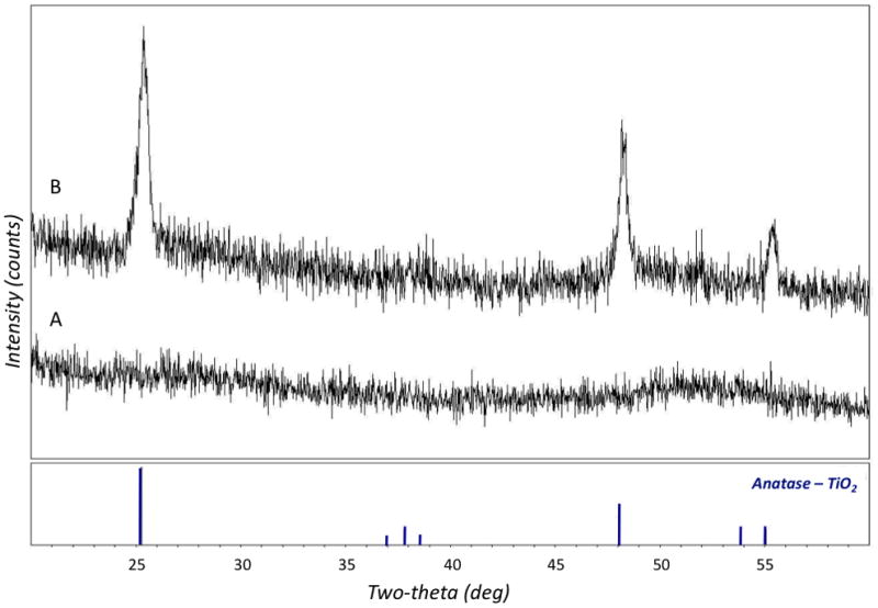
The glancing incidence X-ray diffraction (GIXRD) pattern of a 50 nm TiO2 film freshly after sputtering (A) and after annealing for 1 hour at 450°C in inert nitrogen environment (B). The bottom portion of the graph shows the expected peaks locations and relative peak intensities for pure anatase TiO2.
The decomposition rate of an organic compound such as MB is widely considered to be a good estimate for the efficiency of TiO2 photocatalytic activity14–18. Figure 6 shows the results of MB discolorations, obtained when the solution was pumped through the device at different flow rates and under bias voltages ranging from no bias to 5V bias (at increasing steps of 1V). Data are displayed in terms of “residence time”, the average time a fluid particle resides in the channel, which ranges from 7.5s (100 μl/min flow rate) to 150s (5μl/min flow rate). The data show that the concentration of MB in the flow chamber decays exponentially over time, indicating that the oxidative capacity of the device is constant over time19.
Figure 6.

Methylene blue degradation in terms of residence time (5 flow rates have been investigated, ranging from 5 μl/min to 100 μl/min). Six bias voltage conditions have been tested, starting by no bias voltage applied (less than 20% color removed in 150s) to 5V (about 95% color removed in 150s). The data show that the concentration of MB in the flow chamber decays exponentially over time, indicating that the oxidative capacity of the PC is constant over time. The data are shown as mean ± standard deviation of normalized concentration values.
Each curve in the figure represents the color removal occurring with different applied bias voltages. The pure photodecomposition (0V bias voltage) is quite slow, removing about 20% of the color at a flow rate of 12.5 μl/min. It was found, however, that the color removal was increasing together with the applied bias voltage. Through the application of external bias voltage to photocatalytic process (called electrochemically assisted photocatalytic process or photoelectrocatalytic process), the photocatalyst acts as a photoanode, driving the photogenerated electrons and holes in opposing directions so that the charge recombination is retarded9–11. UV rays and electrolysis themselves can induce the decomposition of MB20. For this purpose, discoloration tests have been specifically carried out. A pure PDMS/quartz device was lighted by the UV source, yielding to a not measurable MB decomposition at a flow rate of 5 μl/min. Furthermore, a device provided with two Pt electrodes was used to quantify the decomposition due to electrolysis; in the case of 5V bias potential and a flow rate of 5 μl/min, the measured decrease in MB concentration was less than 5%. Bubble formation was never observed in the 0-3V bias potential range; bias potentials of 4V and 5V led to bubble formation on the electrode surfaces when the test was excessively protracted in time. The 3V bias potential was thus considered an optimal compromise for the subsequent blood experiments. Concerning blood tests, UV-induced dissolved oxygen (DO) production and associated changes in oxyhemoglobin concentration were measured in stabilized mixed blood at 12.5 μl/min through the test cell. At this flow rate, the resultant residence time within the cell was 60 seconds. UV exposure to the photocatalyst films resulted in almost a complete (SO2=96.6±1.6%) hemoglobin saturation in the case of using blood in physiological venous conditions (SO2=75.7±1.3%), as shown in Figure 7. The total oxygen content in blood (CaO2) was calculated from the data by using the oxygen content equation (Eq.1):
| (1) |
where κ is the oxygen affinity to hemoglobin (κ =1.34 ml O2/g Hb), α is the oxygen solubility in blood. The resulting increase in CaO2 resulted to be almost constant, independently from its initial value, and equal to 4.06±0.32 mlO2/dl. The DO generation rate for the photocatalyst was then calculated from the data to be 8.45×10⁻⁵ mmol O2/s, yielding a DO flux at the photoanode of 4.06×10⁻³ mmol O2/(cm2 min).
Figure 7.

Total oxygen content in bovine blood before and after the oxygenation experiments (IN and OUT, respectively) at 5 different initial hemoglobin saturation levels measured by means of a commercial blood gas analyzer. The data are shown as mean ± standard deviation of calculated values.
Discussion
Photocatalytic cells, especially the ones based on semiconductors such as TiO2, are becoming more and more popular as means to oxygenate fluids, thus making it possible for their future application in the biomedical field, e.g. for real time oxygenation of venous blood. Despite the encouraging premises, however, several are the limitations of currently available PCs, hindering the translation of such a technology from the bench to the clinics. First of all, traditional PCs apply to static fluids, thus making it difficult to obtain satisfactory efficiency values of the photocatalytic reactions. Secondly, the use of biocompatible materials, such as semiconductors, as photocatalysts, in PCs is heavily hindered by the difficulty to synthesize the appropriate crystalline phases (as it happens in the case of TiO2).
In an attempt to overcome the above mentioned limitations of PCs and reasoning that dynamic flow conditions could promote an increase in photocatalytic efficiency of the cells themselves, in this study we accomplished the design, realization and validation of a novel, highly efficient flow-through device based on the photocatalytic ability of titanium dioxide to oxygenate blood.
A first step we moved towards the increase of overall efficiency was the development of a consistent protocol to obtain TiO2 thin films not only constituted of pure anatase crystal phase, but also provided with satisfying photocatalytic properties. Indeed, no direct correlation between the TiO2 crystallinity and its efficiency in the photocatalytic action has been found yet21–22, thus complicating the design optimization of PCs. A further step was represented by the peculiar design of the PC, which allowed to apply an external bias voltage between the electrodes while keeping the flow in motion.
The prototype photocatalytic cell, shown in Figure 4, has been characterized in terms of crystallinity and phase of the TiO2 thin film, and in terms of photocatalytic action by means of MB decomposition tests. Finally, experiments on venous bovine blood were performed so as to evaluate the efficiency as oxygenator of the designed device.
MB solution has been reduced in a very short time (in the order of 1 minute) as compared to standard tests reported in literature17–18, where the reduction occurred in hours. Being this performance partially due to the thin flow layer used in our protocol, we believe that an overall higher efficiency can be preserved by realizing a similar device integrating numerous parallel channels. Although the low flow rates involved are compatible with the testing on small animal models, the presented devices could be found useful without significant improvements either in small-scale in vitro blood experiments or in some cell culture applications, for the oxygenation of the culture medium.
The applied bias voltage has been demonstrated to enhance the photocatalytic activity, even if an appropriate tuning of the induced photocurrent is still to be carried out. In particular, for combinations of bias voltages above 3V and low flow rates, bubbles formation has been observed, which can eventually reduce the overall efficiency (or even cause a clog in the microchannel).
Control experiments have also been performed where the photocatalytic chamber was substituted by a simple glass/PDMS chamber, and neither variations in terms of oxyhemoglobin concentration nor gases partial pressure were registered, thus excluding the hypothesis of transport of gases through the tubing walls.
The presented results demonstrated that the proposed photocatalytic cell has the ability to fully oxygenate venous blood, thus improving the results obtained in previous works6, 23, where only a partial oxygenation was reached. Higher oxygen production values were recently reported7–8. However in these studies, experiments were performed in a stationary environment and the full blood oxygenation required about 2 hours. Also in our previous work6, although experiments were performed in a real-time fashion and enhanced through externally applied bias voltage, the oxygen production was about 2 orders of magnitude lower than the one reported in the present work (6.25×10⁻⁵ mmol O2/(cm2 min)). The pH and pCO2 did not have any relevant variation for the five configurations tested. Even if a drop in pH was expected due to the increased H+ ion production from the reaction, blood was probably able to buffer the H+ ions excess. In spite of the endogenous buffering ability of blood, discussed in previously reported works5, 7, the removal of carbon dioxide molecules is an issue which must be addressed in order to fully arterialize venous blood.
The peculiarity to treat flowing medium renders the presented photocatalytic cell design a readily available source of oxygen, allowing its use in real-time applications.
However, further studies are still needed. In particular, the geometry of the photocatalytic chamber plays a crucial role both in the reaction process (due to the effective active surface area) and in the overall blood hemolyticity24. Although red blood cells were not present within our devices after experiments, sedimentation and aggregation represent issues which must be faced prior to any step further towards a possible clinical application. Moreover, erythrocytes cannot be considered uniformly distributed when blood flows in microsized channels, mainly due to plasma skimming and Fahraeus-Lindqvist effects. Such considerations, together with the asymmetrical distribution of oxygen molecules in PCs (as they only are released from the ITO/TiO2 electrode), suggest that both theoretical and computational studies of particles and gas exchange dynamics could enormously contribute to a better understanding of the complex phenomena involved.
Moreover, the effects of UV light on blood must be carefully evaluated before an actual device can be made available for clinical use.
Acknowledgments
This work was partially supported by National Institute of Health (grant #RO1-HL086652) and Progetto Roberto Rocca.
Footnotes
Publisher's Disclaimer: This is a PDF file of an unedited manuscript that has been accepted for publication. As a service to our customers we are providing this early version of the manuscript. The manuscript will undergo copyediting, typesetting, and review of the resulting proof before it is published in its final citable form. Please note that during the production process errors may be discovered which could affect the content, and all legal disclaimers that apply to the journal pertain.
Contributor Information
Marco Rasponi, Email: marco.rasponi@polimi.it, Dipartimento di Bioingegneria, Politecnico di Milano, Piazza Leonardo da Vinci 32 – 20133 Milano, +390223993377.
Tania Ullah, Email: tania_u@mit.edu, Department of Mechanical Engineering, Massachussetts Institute of Technology, 77 Massachussetts Avenue.
Richard J Gilbert, Email: rgilbert@mit.edu, Department of Mechanical Engineering, Massachussetts Institute of Technology, 77 Massachussetts Avenue.
Gianfranco B Fiore, Email: gianfranco.fiore@polimi.it, Dipartimento di Bioingegneria, Politecnico di Milano, Piazza Leonardo da Vinci 32 – 20133 Milano.
Todd A Thorsen, Email: thorsen@LL.MIT.EDU, Lincoln Laboratory, Massachussetts Institute of Technology, 77 Massachussetts Avenue, +17819815227.
References
- 1.Fujishima A, Honda K. Electrochemical photolysis of water at a semiconductor electrode. Nature. 1972;238(5358):37–8. doi: 10.1038/238037a0. [DOI] [PubMed] [Google Scholar]
- 2.Mills A, Le Hunte S. An overview of semiconductor photocatalysis. Journal of Photochemistry and Photobiology A: Chemistry. 1997;108(1):1–35. [Google Scholar]
- 3.Yoshihisa O. In: Photocatalysis: Science and Technology. Kaneko M, editor. Springer; New York: 2002. pp. 9–28. a.I.O. [Google Scholar]
- 4.Hoffmann MR, et al. Environmental Applications of Semiconductor Photocatalysis. Chemical Reviews. 1995;95(1):69–96. [Google Scholar]
- 5.Gilbert RJ, et al. Photocatalytic generation of dissolved oxygen and oxyhemoglobin in whole blood based on the indirect interaction of ultraviolet light with a semiconducting titanium dioxide thin film. Journal of Applied Physics. 2007;102(7) [Google Scholar]
- 6.Monzyk BF, et al. Photolytically driven generation of dissolved oxygen and increased oxyhemoglobin in whole blood. Asaio Journal. 2006;52(4):456–466. doi: 10.1097/01.mat.0000219086.39192.9a. [DOI] [PubMed] [Google Scholar]
- 7.Subrahmanyam A, Arokiadoss T, Ramesh TP. Studies on the oxygenation of human blood by photocatalytic action. Artificial Organs. 2007;31(11):819–825. doi: 10.1111/j.1525-1594.2007.00468.x. [DOI] [PubMed] [Google Scholar]
- 8.Subrahmanyam A, Ramesh TP, Ramakrishnan N. Oxygenation of human blood using photocatalytic reaction. Asaio Journal. 2007;53(4):434–437. doi: 10.1097/MAT.0b013e3180640cc1. [DOI] [PubMed] [Google Scholar]
- 9.Kesselman JM, Lewis NS, Hoffmann MR. Photoelectrochemical degradation of 4-chlorocatechol at TiO2 electrodes: Comparison between sorption and photoreactivity. Environmental Science & Technology. 1997;31(8):2298–2302. [Google Scholar]
- 10.Ku Y, Lee YC, Wang WY. Photocatalytic decomposition of 2-chlorophenol in aqueous solution by UV/TiO2 process with applied external bias voltage. Journal of Hazardous Materials. 2006;138(2):350–356. doi: 10.1016/j.jhazmat.2006.05.057. [DOI] [PubMed] [Google Scholar]
- 11.Vinodgopal K, Kamat PV. Combine electrochemistry with photocatalysis. Chemtech. 1996;26(4):18–22. [Google Scholar]
- 12.Xia YN, Whitesides GM. Soft lithography. Angewandte Chemie-International Edition. 1998;37(5):551–575. doi: 10.1002/(SICI)1521-3773(19980316)37:5<550::AID-ANIE550>3.0.CO;2-G. [DOI] [PubMed] [Google Scholar]
- 13.Al Mamun NH, Dutta P. Patterning of platinum microelectrodes in polymeric microfluidic chips. Journal of Microlithography Microfabrication and Microsystems. 2006;5(3) [Google Scholar]
- 14.Houas A, et al. Photocatalytic degradation pathway of methylene blue in water. Applied Catalysis B-Environmental. 2001;31(2):145–157. [Google Scholar]
- 15.Lachheb H, et al. Photocatalytic degradation of various types of dyes (Alizarin S, Crocein Orange G, Methyl Red, Congo Red, Methylene Blue) in water by UVirradiated titania. Applied Catalysis B-Environmental. 2002;39(1):75–90. [Google Scholar]
- 16.Lakshmi S, Renganathan R, Fujita S. Study on Tio2-Mediated Photocatalytic Degradation of Methylene-Blue. Journal of Photochemistry and Photobiology a-Chemistry. 1995;88(2–3):163–167. [Google Scholar]
- 17.Matthews RW. Photocatalytic Oxidation and Adsorption of Methylene-Blue on Thin-Films of near-Ultraviolet-Illuminated Tio2. Journal of the Chemical Society-Faraday Transactions I. 1989;85:1291–1302. [Google Scholar]
- 18.Zhang TY, et al. Photooxidative N-demethylation of methylene blue in aqueous TiO2 dispersions under UV irradiation. Journal of Photochemistry and Photobiology a-Chemistry. 2001;140(2):163–172. [Google Scholar]
- 19.Kuo WS, Ho PH. Solar photocatalytic decolorization of methylene blue in water. Chemosphere. 2001;45(1):77–83. doi: 10.1016/s0045-6535(01)00008-x. [DOI] [PubMed] [Google Scholar]
- 20.Panizza M, et al. Electrochemical degradation of methylene blue. Separation and Purification Technology. 2007;54(3):382–387. [Google Scholar]
- 21.Wu N, et al. Shape-Enhanced Photocatalytic Activity of Single-Crystalline Anatase TiO2 (101) Nanobelts. Journal of the American Chemical Society. 2010;132(19):6679–6685. doi: 10.1021/ja909456f. [DOI] [PMC free article] [PubMed] [Google Scholar]
- 22.Yang HG, et al. Anatase TiO2 single crystals with a large percentage of reactive facets. Nature. 2008;453(7195):638–41. doi: 10.1038/nature06964. [DOI] [PubMed] [Google Scholar]
- 23.Dasse KA, et al. Development of a photolytic artificial lung: Preliminary concept validation. Asaio Journal. 2003;49(5):556–563. doi: 10.1097/01.mat.0000084140.85987.4d. [DOI] [PubMed] [Google Scholar]
- 24.Gilbert RJ, et al. Computational and functional evaluation of a microfluidic blood flow device. Asaio Journal. 2007;53(4):447–455. doi: 10.1097/MAT.0b013e3180a5e8ab. [DOI] [PubMed] [Google Scholar]