Abstract
Today’s most successful surgical robots are perhaps surgeon-driven systems, such as the daVinci (Intuitive Surgical Inc., USA, www.intuitivesurgical.com). These have already enabled surgery that was unattainable with classic instrumentation; however, at their present level of development, they have limited utility. The drawback of these systems is that they are independent self-contained units, and as such, they do not directly take advantage of patient data. The potential of these new surgical tools lies much further ahead. Integration with medical imaging and information are needed for these devices to achieve their true potential. Surgical robots and especially their subclass of image-guided systems require special design, construction and control compared to industrial types, due to the special requirements of the medical and imaging environments. Imager compatibility raises significant engineering challenges for the development of robotic manipulators with respect to imager access, safety, ergonomics, and above all the non-interference with the functionality of the imager. These apply to all known medical imaging types, but are especially challenging for achieving compatibility with the class of MRI systems. Even though a large majority of robotic components may be redesigned to be constructed of MRI compatible materials, for other components such as the motors used in actuation, prescribing MRI compatible materials alone is not sufficient. The electromagnetic motors most commonly used in robotic actuation, for example, are incompatible by principle. As such, alternate actuation principles using “intervention friendly” energy should be adopted and/or devised for these special surgical and radiological interventions.
This paper defines the new concept of Multi-imager Compatibility of surgical manipulators and describes its requirements. Subsequently, the paper gives several recommendations and proposes new actuation principles for this concept. Several implementations have been constructed and tested, and the results are presented here. This is the first paper addressing these issues.
Keywords: Medical imaging, MRI compatible materials, surgical robotics
INTRODUCTION
Today’s surgical robots are, as a top level classification, surgeon-driven and image-guided (1). Surgeon-driven systems such as the daVinci (Intuitive Surgical Inc., USA, www.intuitivesurgical.com) are the most popular and this is probably motivated by the reduced complexity of these systems compared to image-guided systems. This does not mean that daVinci is simple, but that daVinci is an independent, self-contained unit. Practically, there is nothing wrong in having the surgeon control the robot from a console, but medical imaging and information should be integrated for achieving the true potential of robotics in medicine. Surgical robots should become elements of a complex information system especially designed to work in an operating room, an entire continuity of healthcare from pre-op planning, to image-guidance and intra-operative navigation, to post-op care and, nevertheless, follow-up (2). Surgical robots should be components of computer-integrated surgical systems, information-to-action integrated biomedical systems.
Intraoperative medical imaging is the richest informational component of these systems (3). People use to think that eyes were good enough for surgery, but in fact they are limited to the visual spectrum. Tumors can look like healthy tissue to the naked eye, and even when visible, additional malignant tissue may be obstructed. As such, advanced imaging equipment should be incorporated.
Achieving the compatibility of surgical robots with medical imagers may raise significant problems. This is in fact one of the primary factors beside safety and sterility for which surgical robotics should be purposely designed. Robot compatibility with the class of MR imagers is significantly harder to achieve than other types (1). MRI scanners use magnetic fields of very high density, of the order of one to several Tesla. Ferromagnetic materials exposed to such fields undergo very high intensity rotational and translational forces. In addition MRI imagers use pulsed magnetic and radio frequency fields, thus inducing electricity in conductive elements, creating electrical interference, and overheating.
The extreme requirements of MRI compatibility bring up the issue of multi-imager compatibility, the compatibility with all known classes of medical equipment. If MRI compatibility is fulfilled, few additional requirements should be satisfied in order to include all classes. Multi-imager compatibility allows not only for performing procedures with the most appropriate imager, but also for using cross-platform, combined imaging modalities.
Interest in MRI compatible instrumentation has increased especially after the development of interventional, open MRI (3). The number of MRI compatible surgical instruments and endoscopes has already reached a substantial level, a multitude being commercially available today.
Many researchers focused on material compatibility with the MRI environment (4, 5). Schenck (6) defined the concept of magnetic compatibility and classified numerous materials. He also provided a guidebook for the compatibility of many medical instruments. A comprehensive presentation of MRI compatibility and guidelines for the instrumentation used, and specific tests for MRI compatibility are given by General Electric (GE) (7).
A study regarding the MRI compatibility of mechatronic devices was presented by Chinzei et.al (8), who also designed several versions of an MRI compatible manipulator for open MRI in a collaboration between the AIST-MITI, Japan and the Brigham and Women’s Hospital, USA. It presents five degrees of freedom (DoF) actuated by ultrasonic (piezoelectric) motors. The manipulator is located between the vertical “donuts” of the MRI, above the surgeon’s head, and presents two long arms that extend into the imaging region, close to the patient. The system is designed to serve as an image-guided surgical assistant integrating preoperative planning and intra-operative MRI. More recently, Chinzei also reported on his progress on the development of a new MRI manipulator (9) in Japan.
An MRI compatible needle insertion manipulator, also using ultrasonic actuation, was built by Masamune et al. at the Medical Precision Engineering lab of the University of Tokyo (10). The system was designed for neurosurgery applications and tested in-vitro. The development of a robotic system for breast lesions biopsy and therapy under MR guidance has been developed in Germany (11). It comprises a six DoF manipulator for positioning MR compatible instruments in close proximity of the imager’s isocenter. The robot is electrically actuated with ultrasonic motors located in a control and driving unit distal from the high-intensity magnetic field. The system has been successfully tested in-vitro showing an instrument targeting accuracy of less than 3 mm. The Karlsruhe research team also reported the development of several versions of a robot for MRI guided mammography (12), ROBITOM. A new system of the Karlsruhe group is under development (13). This uses piezoelectric motors for the actuation of the robot, and pneumatic actuation for the end-effector gripper and needle insertion stage. A well documented discussion on the advantages offered by pneumatic actuation in MRI environments is presented.
The MRI guided robotic systems developed thus far use ultrasonic actuation. This is a special technology based on piezoelectric elements using high frequency electrical excitation. This technology eliminates the magnetic fields of electromagnetic motors, but still requires conductive components due to the electrical energy used. For this reason, ultrasonic motors may create electromagnetic induction and interference problems and should be maintained distal from the imaging region. In addition, piezoelectric motors typically use high voltages, thus raising safety concerns.
This paper presents the concept of multi-imager compatibility and several alternate actuation principles using other energy types that are better suited for medical applications. These basic components are intended to start filling the gap of motorization technology to be used in conjunction with imaging devices.
MULTI-IMAGER COMPATIBILITY
Multi-imager compatibility is the simultaneous compatibility of instrumentation with all classic and interventional classes of imaging equipment based on ultrasound, X-ray, and magnetic resonance. The requirements of multi-imager compatibility are prescribed based on MRI compatibility in view of the fact that these are the most demanding criteria.
According to the GE test guidelines (7) a device shall be considered MRI compatible if and only if:
It is MRI safe: It presents no additional risk for the patient and operator;
Its use in the MRI environment does not adversely impact the image quality;
It performs its intended function when used in the MRI environment in a safe and effective manner.
Other common operating room requirements concerning safety and sterility are being addressed independent of the MRI compatibility. GE also defines four zones of MRI compatibility; a device meeting the MRI compatibility definition is compatible with:
-
Zone 1
If it may remain in the imaging volume and in contact with the patient throughout the procedure and MRI scanning;
-
Zone 2
If it may remain in the imaging volume and in contact with the patient throughout the procedure and scanning but is not located in the image’s region of interest;
-
Zone 3
If it will typically be used within the imaging volume, but will be removed during scanning or when not in use;
-
Zone 4
If it is suitable for use in the magnet room during the procedure when kept more than one meter from the iso-center or beyond the 200 Gauss (20 mTesla) line.
In this definition the degree of MRI compatibility depends on the use of the device. The degree of MRI compatibility is designated Zone 1 to 4 MRI compatible, the highest level of MRI compatibility being Zone 1.
GE also classifies several materials with respect to the above compatibility zones depending on the material’s magnetic susceptibility (χ). Materials with χ closer to human tissue (−9.05 ppm), and air (0.36 ppm) would be most desirable for Zone 1 instruments. Zone 1 compatibility materials are sub-classified into 3 groups depending on the material’s magnetic susceptibility difference from that of tissue Δχ:
-
Group 1
Materials with essentially no detectable image artifacts when inside tissue (Δχ < 3 ppm). Examples of such materials are: nylon, silicon nitride ceramics, teflon, polysulfone, carbon fiber composites, vespel, plexiglass, zirconia ceramics, wood, and copper;
-
Group 2
Materials associated with noticeable, but often insignificant, image artifacts (Δχ < 10 ppm). Examples of such materials are: alumina ceramics, silicon, quartz, lead, and zinc;
-
Group 3
Materials associated with easily noticed artifacts, but often acceptable for particular applications. (Δχ < 200 ppm). Examples are: titanium, molybdenum, tungsten, graphite, tantalum, elgiloy, esbrid ceramics, zirconium, and aluminum.
We define multi-imager compatibility in a similar manner, by augmenting the class of X-ray and ultrasonic imagers to the GE definition of MRI compatibility.
For compatibility with the group of X-ray based imagers the principal requirement relates to the radiolucency (X-rays transparency) of the device. This is especially important in applications using X-ray fluoroscopy for Zone 1 devices. For example, in performing percutaneous needle access under C-Arm guidance with AP (anterior-posterior) visualization, the robotic end-effector holding the needle should not impede the visualization of the target. Ultrasonic imagers do not impose additional requirements. Multi-imager compatible instruments should not interfere with the normal functionality of the imager, should not create artifacts or image distortion, and should not impede the visualization of the anatomical target.
But do multi-imager compatible materials exist, and if so, could those be used for fabricating precise robotic components? For proving the feasibility of the multi-imager compatibility approach we performed a study showing the existence of materials satisfying the combined imager requirements. Moreover, we evaluated the capability of using such materials for the fabrication of highly stressed, precision parts.
After filtering a large spectrum of materials based on MRI compatibility, mechanical properties, and manufacturing capability, based on availability we selected five materials: 7075 aluminum, titanium, glass-mica ceramics, polyimide, and aluminum silicate ceramics. Then, we used these materials to fabricate several high precision parts [worm and worm gear in a special Ball-Worm transmission (14)]. Figure 1 presents a photograph of the fabricated parts listed in Table 1, an MR image acquired with these components placed around the head, and an X-ray of some of these parts.
Figure 1.
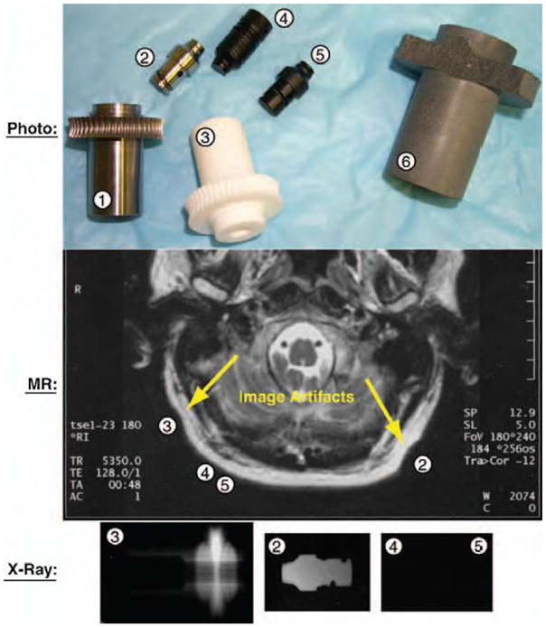
Photograph, MRI, and X-ray images of test parts.
Table 1.
Tested parts and materials used
|
Figure 1 |
Designation | Material |
|---|---|---|
| Part No | ||
| 1 | Worm Gear | 7075 Aluminum |
| 2 | Worm Peg | Titanium |
| 3 | Worm Gear | Glass-Mica Ceramics |
| 4 | Worm | Polyimide |
| 5 | Worm Peg | Polyimide |
| 6 | Worm Gear | Aluminum Silicate Ceramics |
The CNC (computer numeric control) manufacturing the ceramic (Figure 2), titanium, and polyimide parts required several iterations of selecting cutting tools and adequate parameters. Except for the aluminum silicate ceramic part (6), which broke repeatedly during machining, all other parts have been successfully manufactured according to the desired precision and surface quality. The manufacturing test eliminated the aluminum silicate material.
Figure 2.
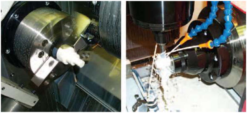
Manufacturing a ceramic part in the CNC lathe and milling machines.
An initial MRI safety test was performed on a Philips imager of 1.5 Tesla by evaluating the force exhibited by each part when located in close proximity of the MR isocenter. This step eliminated the 7075 aluminum part (1), which exhibited perceivable interaction torque when moved inside the tunnel.
All remaining parts have then been located next to a subject’s head, at locations specified by the corresponding part numbers (2, 3, 4, and 5) in Figure 1. The MRI image shows that the polyimide parts (4, 5) did not distort the image, and the titanium (2) and glass-mica ceramic (3) parts produced minimal artifacts. In this test all parts have been considered to perform acceptably.
The X-ray test was then performed. The X-rays of Figure 1 shows a clear contour of the titanium part (2), a vague and thickness-dependent contour of the ceramic part (3), and almost perfect radiolucency of the polyimide parts (4, 5), which could only be observed under a very careful examination under special lighting.
Even though this is not a comprehensive material study, the results of these tests show the existence of at least one ideal multi-imager compatible material proper for robotic fabrication, the polyimide. This belongs to the class of Vespel materials, found by GE to have no detectable MR artifacts. Polyimide also presents outstanding compressive strength, a wide temperature range, no melting (allowing for sterilization), low friction (requiring no lubrication), good chemical resistance (sterilization), and very low electrical and thermal conductivity (dielectric). The aluminum silicate ceramic material was found to be acceptable, provided that the cross section of the parts to be constructed was maintained below 6 mm (radiolucency). Due to their excellent compressive strength (50,000 psi) and surface hardness, ceramics are good candidates for constructing highly stressed components which are not susceptible to shocks. A wider range of materials will need to be evaluated in order to identify additional multi-imager compatible materials with acceptable machinable properties. In general, Zone 1 multi-imager compatible materials are non-magnetic, dielectric, and present good radio radiolucency properties.
Material selection, evaluation, and testing protocols
The following methodology is suggested in selecting materials for multi-imager compatibility:
-
Start with the MRI Zone 1 compatible materials, since this criterion most significantly reduces the pool. According to GE specifications (7) such materials present magnetic susceptibility close to water and tissue. Examples of MRI compatible materials are:
Non-ferrous metals: aluminum, beryllium, copper, lead, magnesium, nickel, gold, silver, platinum, palladium, tin, titanium, zinc, zirconium, etc;
Ferrous metals: 300 series stainless steel;
Special materials and plastics: carbon, advanced ceramics, glass, acetal, acrylic, alkyd, allyl, epoxy, flouroplastics, etc.
-
Eliminate the materials that:
Are excessively expensive for the application such as precious metals;
Present inadequate mechanical strength;
Are known to present poor manufacturing properties.
Machine small equally sized parts and perform X-ray testing. Eliminate radio-opaque and materials inducing high artifacts;
Test the remaining parts for MRI compatibility. This apparently redundant test is required since working of a material (e.g. machining, molding, bending) may significantly alter its magnetic properties;
Classify the remaining materials with respect to electrical conductivity;
Choose the most appropriate material for the construction of each individual part in the mechanical design based on mechanical, chemical, and electrical properties. Immediate priority is given to dielectrics. If possible, completely eliminate conductive materials. Conductors may only be used for small parts, without loops (electrical induction), which are electrically insolated from the neighboring components.
Manufacture the parts and individually test for MRI compatibility. This is necessary if the manufacturing method and geometry differ from the ones used in point 3.
Assemble and test functionality in all classes of imagers. If necessary, reiterate to step 6 with different materials.
Material selection is a complex process which probably involves multiple reiterations. This is due to the fact that different parts in the actuation module require the use of different materials depending on their functionality. Potential difficulties in material selection are due to the fact that high stiffness MRI compatible materials such as ceramics are extremely brittle. This could cause manufacturing difficulties, but also part failure in the active assembly. Sapphire spherical balls have been found to have outstanding performance for constructing rolling elements, such as custom built bearings. Alternative approaches should address the use of high-stiffness plastics.
Motion accuracy tests
Motion active components of multi-imager compatible instruments require additional testing regarding their accuracy in performing the desired motion task. Initial accuracy tests are performed in the lab, using standard methods. Multi-imager compatibility should also ensure that accuracy is not influenced by the imager. Active devices should be tested to asses their accuracy in performing the desired motion in the presence of the imaging equipment. These motion tests may use image feedback or specially designed test stands, when the accuracy of the imager is not sufficient, when the imager does not provide real time data, and/or when the motion components are unobservable in the image.
Imager compatibility test protocols
Image interference evaluations should be performed by assessing the degree of image degradation due to the presence of the device to be evaluated in the imaging field and potentially due to its motion. Tests include the standard safety and compatibility tests with the imagers used.
A device is considered Zone 1 compatible with a specific imager if:
It presents no additional risk to the patient, imager operator, or medical personnel;
-
Its use in the Zone 1 of the imager does not adversely impact the image quality;
Collect a set of background noise images while the module is not in the imager room;
Install the motion test stand on the imager’s table centered in the imaging field;
Record image data;
Inspect the image for artifacts and compare it with the background noise image;
Calculate the image deterioration factor based on the squared difference imaging (presented next).
It passes the motion accuracy test (listed above) in a safe and effective manner.
Image deterioration factor
A quantifiable measure of image distortion may be determined based on the following algorithm. A mockup of the organ of interest for the clinical application is placed in close proximity to the device to be tested or the stand for testing motion accuracy, as schematically presented in Figure 3.
Figure 3.
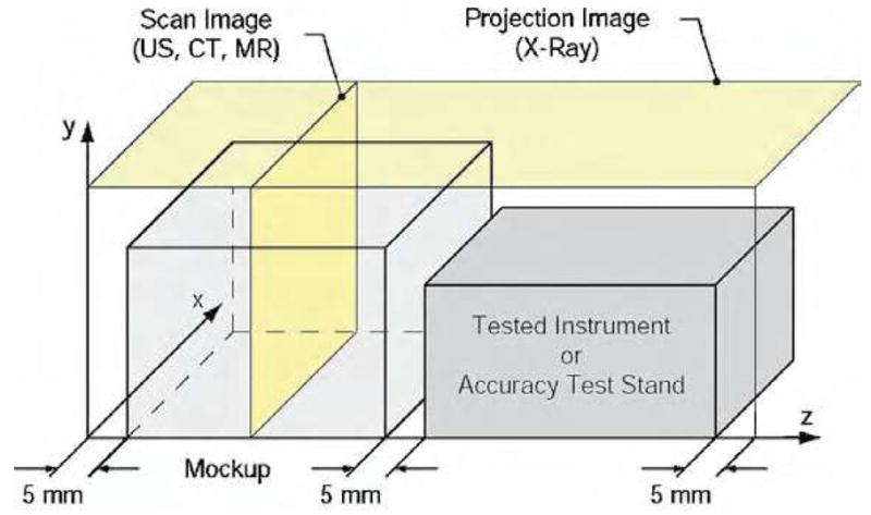
Test setup for multi-imager image deterioration factor.
The mockup and the device/instrument to be tested are placed in the active field of the imager. With the notations presented in Figure 3, ultrasound, CT, and MR imagers acquire images in the XY plane scanning the Z coordinate (Scan Image). X-ray fluoroscopy gives a Projection Image in the XZ plane. Two tests are employed for each type of imager:
-
Passive (P): This test provides a quantifiable measure of image deterioration due to the presence of the device in the imager field, when not in motion. Three sets of images (i = 0…2) are acquired through:
-
0
The mockup only;
-
1
The mockup again (to compare with 0 for determining the normal level of noise);
-
2
The mockup and the device placed 5 mm apart.
-
0
-
Active (A): This test depicts image deterioration due to the activation of the device. The test includes the mockup and may include a stand for testing motion accuracy (as described above, in the motion accuracy tests section). Images are acquired while the actuation module is in motion (normal operation conditions). Similarly, three sets of images (i = 0…2) are acquired through:
-
0
The mockup, device at rest, and the accuracy stand placed 5 mm apart;
-
1
Case 0 again (reference measurement);
-
2
Same setup in motion.
-
0
An image deterioration factor may be calculated at discrete Z coordinates, as:
where, i is the passive or active test number, is the pixel value in the test Ti for an image pixel depth pd, and rx, ry are the image resolutions in the x respectively y directions of the image slice. For the X-ray fluoroscopy test ry = 1 and for ultrasound experiments z = 1. The image deterioration factor may then be plotted as a function of the z coordinate. A typical graph is depicted in Figure 4.
Figure 4.
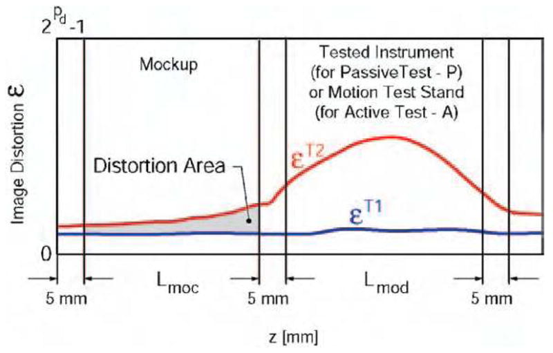
Normal (T1) and induced (T2) image distortion along the Z axis.
The error εT1 reflects the normal level of noise in the image. Error εT2 is induced by the presence of the actuation module in the imaging field for the passive test (P) or solely caused by the activation of the instrument/device in the case of the active test (A). The area between the two plots in the region of interest may be used to calculate an overall image deterioration factor. This is averaged over the length of the mockup Lmoc in the z direction by comparison with the corresponding reference set, as follows:
The equation above gives a global image deterioration factor for each type of imaging equipment due to the presence of the actuation motion in the imaging field (Ep) and exclusively caused by its activation (EA). The device is considered to induce low image interference if these values are small. This should initially be correlated with observations made by experienced radiologists visually comparing the image sets. In our experience Ep < 2% and EA < l% were associated with minimal or unobservable interference perceivable by radiologists.
Multi-imager compatibility checklist
The multi-imager compatibility tests may be summarized in a checklist table, as presented in Table 3. An active device is considered multi-imager compatible if it passes all tests listed above. Passive devices are excluded from the active tests.
Table 3.
Multi-imager compatibility checklist
| Criteria | Test | Desired | Achieved | Passed/Failed | |
|---|---|---|---|---|---|
| Lab Test | Motion Accuracy | < 0.1 ° | 0.024° | Passed | |
| Size | Volume < 0.35 L | 0.09 L | Passed | ||
| Magnetism (GE Magnet Test (20)) | Lifting force < 125 N | 0.0 N | Passed | ||
| Safe to test with ultrasound imager | Passed | ||||
| Clinical Engineering | Safe to test in X-ray Fluoroscopy Imagers | Clinical Engineering Sticker | Passed | ||
| Safe to test in CT Scanners | Passed | ||||
| Safe to test in MRI Scanners | Passed | ||||
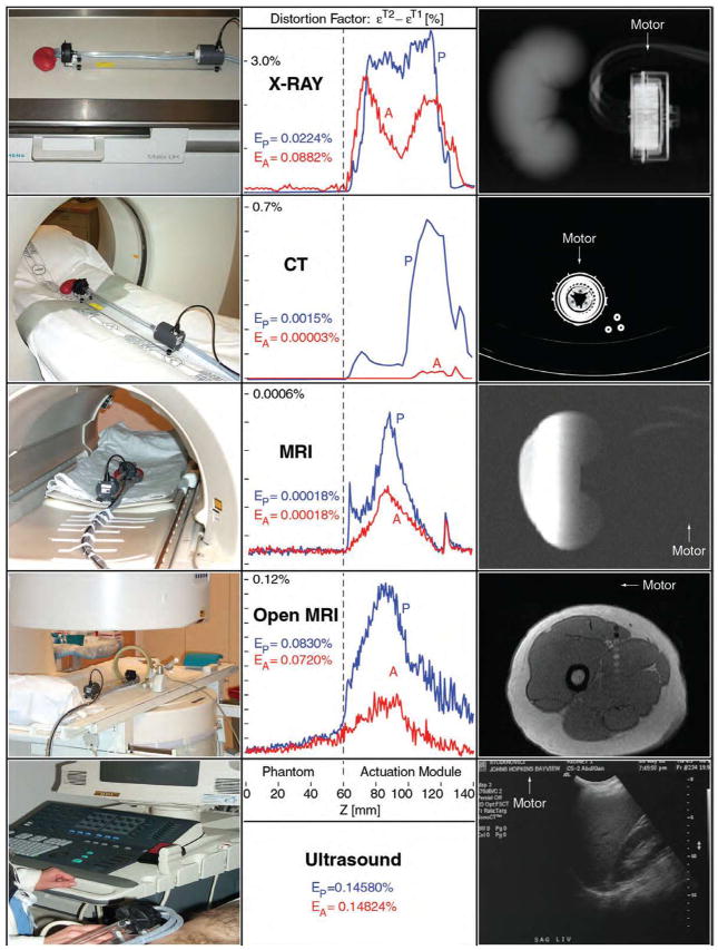
| Ultrasound | Passive | EP < 2% | 0.145800% | Passed | |
| Active | EA < 1% | 0.148240% | Passed | ||
| X-ray | Passive | EP < 2% | 0.022400% | Passed | |
| Active | EA < 1% | 0.088200% | Passed | ||
| Image Distortion Tests | CT Scanner | Passive | EP < 2% | 0.001500% | Passed |
| Active | EA < 1% | 0.000032% | Passed | ||
| MRI | Passive | EP < 2% | 0.000188% | Passed | |
| Active | EA < 1% | 0.000187% | Passed | ||
| Open MRI | Passive | EP < 2% | 0.083000% | Passed | |
| Active | EA < 1% | 0.072000% | Passed | ||
| Multi-Imager Compatibility | Passed | ||||
MULTI-IMAGER COMPATIBLE ACTUATION PRINCIPLES
Achieving imager compatibility for motion active devices in medical instruments is a challenging engineering task. Compared to passive devices, these impose additional requirements, related to the transmission and especially the generation of motion. The ultrasonic motors reported by authors in MRI compatible robots are not Zone 1 compatible components. As such, new methods and motor designs need to be derived and utilized, in order to fully exploit the coupled capabilities of imager-robot systems.
In general, materials used for multi-imager compatibility should be non-magnetic, dielectric, and radiolucent. The actuation and sensing principles used in multi-imager compatible robots and active devices should not be based on magnetism. The use of electricity is acceptable under certain conditions of non-interference and safety. However, if possible for Zone 1 devices the use of electricity should be avoided or limited.
Multi-imager compatible devices may be constructed to present a Zone 1 compatible component (the driver) operating within the imager in close proximity to the patient and imaging field, and a non-compatible component located remotely in the imager’s control room (the instrument/device). This decoupled setup somewhat similar to tele-portation allows for the use of standard robotic components in the control room (computer, motion control cards, amplifiers, and motion transmission equipment) for the operation of specially designed components in the imager’s room. A very promising candidate for the actuation of Zone 1 compatible devices is the pneumatic/hydraulic actuation. In this setup pumps, valves, or distributors in the control room could be used to drive pneumatic/hydraulic motors within the imager.
Even though many types of fluid power motors are known and commercially available, several issues are still raised by the stringent constraints of multi-imager compatibility. Most, if not all commercially available fluid power motors present incompatible materials in their construction. In addition, most types are uncontrollable or notoriously hard to precisely control. The dentist’s drill for example uses an air turbine that can achieve very high rotation speeds and is very powerful for its size, but may not be precisely positioned at a given angle.
In addition, the encoding to be used in multi-imager compatible motors requires special principles and implementation to minimize or eliminate the use of conductive materials and electricity. Ideally, the encoding should be performed altogether in the controller room. This can be achieved by using a mechanically phased transmission of motion from the driver located in the control room to the device located in the imager’s room. With this, the motion of the device could be measured and controlled by measuring and controlling the motion of the drive mechanism.
Several fluid power actuation principles using pneumatic or hydraulic energy are proposed here as feasible alternatives for robotic systems designed to operate in multi-imager compatible environments.
HARMONIC MOTORS
A harmonic drive is a rotary transmission implementing torque coupling with concentric elements. From the inside out these elements are typically a wave generator, a flexible spline, and a rigid spline. The wave generator, which presents various constructions, forces the flexspline to take the shape of an ellipse so that its external gear teeth engage the inner teeth of the rigid spline in two opposite points. Rotating the major axis of the ellipse causes successive teeth engagement, and generates the rotation of the rigid spline. High transmission ratios are rendered due to the small difference between the number of teeth of the flex and rigid splines.
The harmonic motors proposed next utilize several principles used in classic harmonic drives. These all derived from the simple observation that rotation may be obtained by manually squeezing the flexspline of a high-quality harmonic drive with elliptic bearings.
Harmonic motor with rotary wave actuator
In this principle wave actuation is generated by sequentially “squeezing” the flex spline with at least three pneumatic or hydraulic cylinders, as presented in Figure 5.
Figure 5.
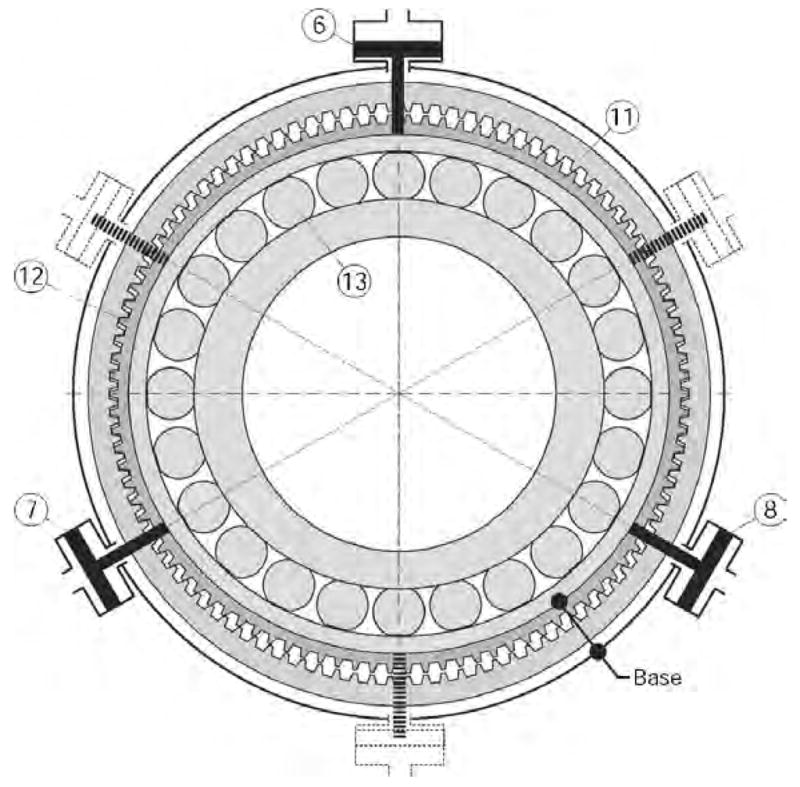
Harmonic motor with rotary wave generator.
Pistons (6), (7), and (8) act on the elliptical outer ring of the wave generator (13) and the flexspline (12). The wave generator (13) is rotated by sequential pulsing of the pistons as presented in the Elliptical Coupling, either by using an elliptical pump arrangement or by pumps/valves actuated independently, such as voice coils. The inner ring (13) is not connected to any other element. A set of mirrored cylinders may also be respectively connected on the same fluid circuits for reducing radial load. The base is represented by the flexspline (12) and the cylinders support, which are connected to each other by using either radial flexible elements or a base gear matching the teeth of the flexspline, as for the harmonic drive.
The main difference compared to the harmonic drive is that the input energy is given by the fluid and not a rotational input, thus rendering a motor rather than transmission. The motor inherits the mechanical performance of the cylinder coupling and harmonic drive, making it suited for precision actuation and multi-imager compatibility.
The harmonic motor is potentially safe to use in surgical applications, especially when driven by a hydraulic agent such as distilled water or even saline. All hydraulic circuits are closed and can be made leak proof by using diaphragm cylinders. The fluid pulses back and forth in the circuits and the system may be operated at low pressures. Should a hydraulic circuit fail, the motor stalls. Moreover, the drive can be made to present low backlash, and it is non-backdrivable if the pump is non-backdrivable. For multi-imager compatibility, the principle allows for remote position sensing.
Harmonic motor with static wave actuator
The static wave actuator version of the harmonic drive presents simpler construction and minimizes the number of moving elements by replacing the elliptical bearing with an arrangement of cylinders which act as a active wave generator. The flexspline remains fixed but its oval shape is dynamically driven by cylinder couplings. Two types of wave actuators are defined based on the direction that the cylinders act, Radial and Tangential.
Radial Wave Actuator
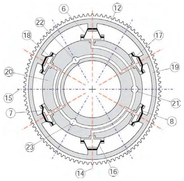
Figure 6 presents a schematic of the Radial Wave Actuator and the flexspline (12). For simplicity the rigid spline (11) has not been represented in this schematic being similar to the one represented in Figure 5. The radial wave actuator comprises a flexible outer ring (19), a series of at least 6 diaphragm cylinders (6), (7), (8), (16), (17), (18) and a rigid cylinder ring (20). The flexspline (12) and the outer ring (19) are assembled or even constructed as a single part. Pairs of opposite cylinders are linked on the same fluid circuits connecting the actuator to a sequential through the ports (21), (22), and (23).
Figure 6.
Radial Wave Actuator.
In un-pressurized state the flexspline (12) – outer ring (19) assembly exhibits circular shape concentric with the cylinder ring (20). When pressure is applied in a circuit the flexspline is deformed along the direction of the pressurized cylinders causing the gear teeth to engage in that direction. Figure 6 presents the wave actuator pressurized in port (21) inducing an oval shape spline with (14) and (15) as major and minor axes respectively. The other two circuits rotate the major elliptical axis to their respective directions. The three 120° spaced axes of the cylinders are primary axes and their number directly determines the precision of motion. However, increasing the number of the cylinder pairs has practical limitations and significantly increases complexity.
The following method allows for doubling the number of axes for the same number of cylinders. The method is based on the observation that if a thin ring is pushed from inside out on opposite sides, it deforms aligning the major axis in that direction. But if the ring is squeezed in the same places, the major axis is reversed 180°. Thus, by pulling the diaphragms inward (rather then pushing outward) a new set of secondary axes is created normal to the primary ones, as represented in Figure 6.
To avoid operating below the atmospheric pressure (for pulling) the diaphragms are preloaded so that in un-pressurized state they exert elastic pull on the outer ring (19). This shifts the operating point above atmospheric pressure in a similar way that spring return pistons operate. This simple method uses the elasticity of the diaphragm in place of the classic return spring. Reducing the pressure below the central operating point causes the flexspline to engage at the secondary axis.
By independently operating each circuit the major axis can be oriented along any of the primary and secondary axes. With careful design of the sequential pump, coupled operation of the cylinders can orient the ellipse in arbitrary orientations providing smooth and precise motion of the rigid spline output.
Diaphragm cylinders are well suited for this application not only for their leak proof operation but also for implementing the spring return. For this reason the diaphragm should be manufactured of materials with good elastic properties. Moreover, as it can be easily observed in the exaggerated oval shape of Figure 6, during motion the piston and cylinder axes lose coaxiallity. Thus, compliant (elastic) diaphragms are also accommodating this misalignment.
Tangential Wave Actuator
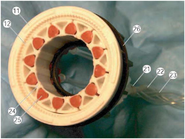
A schematic of the tangential wave actuator and the flexspline (12) is presented in Figure 7. For simplicity the rigid spline (11) has not been represented being similar to the one represented in Figure 5. The tangential wave actuator comprises a special flexible ring (24) and a series of 12 inflatable cylinders (25) (at least 6 inflatable cylinders were found to be required in the design implemented). The flexspline (12) and the wave ring (24) are not assembled so that relative tangential slipping is unrestricted at their contact. Pairs of four opposite cylinders are connected on the same fluid circuits connecting the actuator to a sequential pump through the ports (21), (22), and (23).
Figure 7.
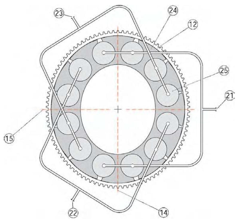
Tangential Wave Actuator.
The wave generator ring (24) has a special construction presenting 12 (at least 6) equally spaced lobes attached to a thin and elastic inner structure. Semi-cylindrical cavities are created between adjacent lobes for placing the inflatable cylinders (pillows). The outer surface of the lobes is constructed of an elliptical surface that matches the region at the major axis of the flexspline ellipse, as presented in the figure.
The actuated oval shape of rotating major (14) and minor (15) axes is induced by sequentially pressurizing the inflatable cylinders (25). When pressure is applied to a circuit, opposite groups of inflatable pillows expand enlarging the gap between adjacent lobes. This deforms the wave generator ring to an oval shape with the major axis aligned in the direction of the pressurized axis. The orientation of the major axis is then rotated by sequential and coupled operation of the three circuits.
We designed, manufactured, and tested a prototype hydraulic harmonic motor with tangential wave actuation. Figure 8 presents a photo of the partially disassembled motor. The motor is entirely constructed of multi-imager compatible materials. The rigid spline (11), the flexspline (12), the base spline (26), and the wave generator (24) are constructed of plastic materials. The inflatable cylinders (25) are silicone rubber tubes with closed ends, which have been connected in three groups of circuits using 1/8″ ID PVC tubing (21), (22), (23). The harmonic drive using a 100 teeth rigid spline and a 98 teeth flexspline implements a 50:1 transmission. The motor presents a hallow shaft, cylindrical shape. The overall size of the motor is ϕ60 mm × 25 mm with a ϕ25 mm bore and it weighs only 50g.
Figure 8.
Prototype harmonic motor with Tangential Wave Actuator.
Tests performed showed that a relatively high operating pressure (~50 psi) was required for achieving sufficient deformation of the wave actuator. Moreover, precision of motion achieved at the output shaft was slightly below 1°, which may not be satisfactory for high precision applications. In addition, in our design the silicone rubber tubes used had limited cycle life.
A hollow shaft cylindrical construction is common for all versions of the Harmonic Motor. This allows for mounting and/or passing additional components/circuits through inside the motor when used in a mechanical assembly. For example, in a serial-link robotic architecture using multiple such actuators, the power lines of the motors can be fed through the bore of the foregoing motors.
Planetary motor with harmonic transmission
This is a new type motor which uses similar principles, but involves planetary rather than harmonic principles. This may again be constructed of multi-imager compatible materials, but potentially presents higher precision of motion than previous types.
A schematic of the actuation module is presented in Figure 9, comprising two motion stages, a planetary motor and a harmonic transmission (gearhead) concentrically located on its outer side. The central most part of the module is a cylinder body (16) presenting three radial cylinders (13). Three diaphragm (14) pistons (11) are attached to the cylinder body with the cylinder caps (15). Each cylinder is pressurized through a nozzle (3) linked to a port (10). The pistons are attached with the screws (12) to a rigid planetary gear (9) engaging an internal gear (8), the wave generator gear. The outer surface of gear (8) is elliptic, acting as a wave generator for the harmonic transmission. An oval needle bearing with the rollers (7) and the cage (6) acts between the outer surface of the gear (8) and the inner surface of the flex-spline (5). The rigid spline (4) is attached to the case of the module (2). The output of the motor is taken from the flex-spline (5) through a passive spline (1) presenting an internal rigid spline.
Figure 9.
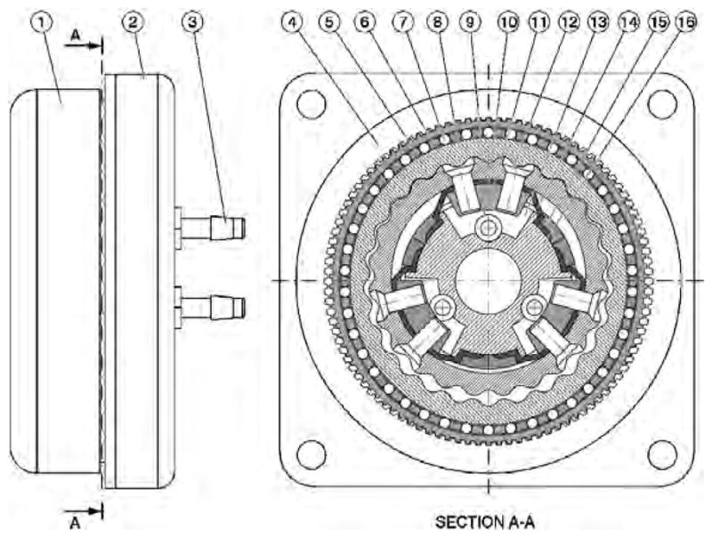
Schematic of the planetary motor with harmonic gearhead.
Fluid pressure is being sequentially applied on the three diaphragm cylinders using a remotely located pneumatic/hydraulic commutation mechanism. This engages the pistons (11) and the planetary gear (9) in a coupled motion around the cylinder body (16) thus engaging the rigid internal gear (8). The planetary gear (9) does not rotate but rather balances on a round trajectory around the cylinder in a quasi-translational motion, its rotation being prevented by the diaphragm (4) connections to the base (16). For each full pressure cycle the gear (8) rotates with one tooth angle. This rotation is further de-multiplied through the next harmonic transmission stage so that the output of the module rotates with a spline tooth angle for each half turn of the wave generator (8).
In the case of pneumatic actuation, a pressure commutation mechanism is represented by three computer-controlled proportional pneumatic valves generating a sequence of three sinusoidal waves of 120° phase shift, using an eccentrically coupled pressure distribution, as for the hydraulic pump presented next. Hydraulic actuation is capable of higher speed performance due to the incompressibility of the agent. This low-pressure hydraulics is also safe for surgical applications. A three-channel hydraulic commutation pump was designed as presented in Figure 10. The pump comprises a cam of cylindrical outer surface (17) eccentrically mounted on a rotating shaft activated by the electric motor (23) through a bevel gear transmission. The inner part of the cam (18) presents a special shape (somewhat elliptical) so that two rollers (19) and (20) can simultaneously roll on the inner and outer sides of the cam implementing a dual acting (push-pull) piston stroke. The rotation of the cam causes the pistons of the three cylinders (21) to move in an eccentrically coupled phase, as required for the planetary motor. The pressure waves are then sent to the motor through the ports (22).
Figure 10.
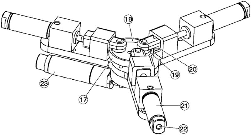
Schematic of the hydraulic commutation pump.
A photograph of the motor-pump assembly and a detail of the motor identifying some key components are presented in Figure 11. Three 6.5m long hydraulic hoses (26) connect the actuation module to (24) to be located in the imager’s room to the pump (25) located in the control room.
Figure 11.
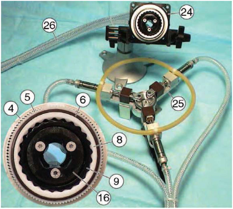
Motor - pump assembly and motor detail.
The motor assembly has been constructed of non-magnetic and dielectric materials such as mica-glass and toughened zirconia ceramics, polyimide plastics, and buna-n rubber. Six small custom-made titanium screws (12) had to be used. The transfer function of the actuation assembly is Tα = 1250, defined as the ratio of the pump and motor rotations, thus being able to achieve high precision of motion.
A multi-imager compatible test stand was also created (Figure 12) on an acrylic platform connecting the motor (24) to an optical encoder (27) with a plastic shaft. The optical encoder is a modified FD-850 fiber-optic encoder (electricity free) by Hathaway Computer Optical Products Inc, presenting a fiber-optic connection (28). The encoder needed to be modified for multi-imager compatibility by remanufacturing and replacing its ferromagnetic components such as bearings, shaft, and casing with plastic, glass, and ceramic parts.
Figure 12.
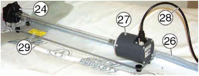
Multi-imager compatible test stand.
A bench test of motion accuracy was first performed. The motor of the commutation pump was controlled from the same PC acquiring the position data from the fiber-optic encoder. In the experiment, the actual position of the output measured by the fiber-optic encoder was compared to the desired output position given by the commutation angle measured by the motor encoder of the pump and passed through the transfer function of the assembly.
The entire setup including the motor mounted on the testing stand and the pump were then tested for safety and imager compatibility with all classes of imaging equipment by the department of Clinical Engineering in our institution. An independent magnetism test has also been conducted to determine the magnetic lifting force by using a 49 lb force magnet. Imager tests have then been performed in all classes of imaging equipment for assessing the degree of image degradation due to the presence of the actuation module in the imaging field (passive test) and due to the activation of the motor (active test), according to the Imager Compatibility Test Protocols described in previous sections.
DICOM images have been acquired and analyzed using the image squared difference method. The image deterioration factors were calculated at discrete Z coordinates in the scan direction along the mockup of the organ and the motor. These were then plotted as a function of the z coordinates and overall image deterioration factors Ep and EA were estimated. These give a global image deterioration factor for each type of imaging equipment due to the presence of the actuation motion in the imaging field (Ep) and exclusively caused by its activation (EA). Visual observation by radiologists comparing the image sets ensured that the numeric values obtained by these algorithms correlate with their estimates. The results of the experiments are summarized in the following table of diagrams and figures, and the values specific to each imager test are reported in the checklist Table 3. These results show that the actuation module presents good accuracy of motion, is imager compatible with all known imager types, and induces imperceptible image deterioration and artifacts. A drawback of the motors presented is their relative reduced speed. This is inherited from the hydraulic/pneumatic commutation used, and is substantially affected by the length of the hoses used to connect the motor to the driver. Our present work addresses variations of the planetary motor design, in order to achieve better torque capabilities at lower operating pressures, new designs of the gears involved, mechanical performance and reliability testing.
The motors presented here are Zone 1 multi-imager compatible. They may be precisely operated within the imager field of any known class of imaging equipment while the imager is acquiring images. This includes the class of MRI imagers for which other types of motors (electric, piezoelectric, ultrasonic) are either incompatible or can not be set in close proximity of the magnetic field, operational or not. Previously reported MRI compatible robots inhabit MRI Zone 4 (one meter from iso-center or beyond the 20 mTesla line) and, therefore, have imprecise manipulation capability within Zones 1 and 2. These motors present relatively small sizes making them appropriate for the construction of image-guided robots operating within the confined space of various imagers, including closed bore tunnel types. This technology could potentially enable the development of new image-guided robotic systems.
CONCLUSION
This paper introduces a new concept for the compatibility of medical instrumentation and surgical robotics with medical imagers. Multi-imager compatibility may be important for giving physicians the ability to select the most appropriate imaging modality in performing robotic interventions, and using cross-platform modalities. The paper also gives several requirements and prescriptions for material selection for this compatibility, and prescribes several test methods for the instrumentation and active devices. The second part of this paper describes several principles for the actuation of multi-imager compatible robots, and finally presents two new types of pneumatic/hydraulic motors that may enable the development of better performance image-guided robots. Present work is related to the development and testing of a new version of a planetary motor with pneumatic actuation, and the results will be presented in future articles.
Table 2.
Multi-imager compatibility results for the planetary motor
|
Acknowledgments
This work was fully supported by grant No. CA88232 from the National Cancer Institute (NCI) of the National Institutes of Health (NIH). The contents are solely the responsibility of the author and do not necessarily represent the official views of NIH-NCI.
References
- 1.Taylor RH, Stoianovici D. A Survey of Medical Robotics in Computer-Integrated Surgery. IEEE Transactions on Robotics and Automation. 2003 Oct;19(5):765–781. http://urology.jhu.edu/urobotics/publications/2003-taylor-ieeetra.pdf.
- 2.Satava RM. The operating room of the future: observations and commentary. Semin Laparosc Surg. 2003 Sep;10(3):99–105. doi: 10.1177/107155170301000302. [DOI] [PubMed] [Google Scholar]
- 3.Jolesz FA. Neurosurgical suite of the future. II. Neuroimaging Clin N Am. 2001 Nov;11(4):581–592. [PubMed] [Google Scholar]
- 4.Holton A, Walsh E, Anayiotos A, Pohost G, Venugopalan R. Comparative MRI compatibility of 316L stainless steel alloy and nickel-titanium alloy stents. Journal of Cardiovascular Magnetic Resonance. 2002;4(4):423–430. doi: 10.1081/JCMR-120016381. <Go to ISI>://000180333100001. [DOI] [PubMed] [Google Scholar]
- 5.Keeler EK, Casey FX, Engels H, Lauder E, Pirto CA, Reisker T, Rogers J, Schaefer DJ, Tynes T. Accessory equipment considerations with respect to MRI compatibility. Journal of Magnetic Resonance Imaging. 1998 JAN-FEB;8(1):12–18. doi: 10.1002/jmri.1880080107. <Go to ISI>://000080143000005. [DOI] [PubMed] [Google Scholar]
- 6.Schenck JF. The role of magnetic susceptibility in magnetic resonance imaging: MRI magnetic compatibility of the first and second kinds. Med Phys. 1996 Jun;23(6):815–850. doi: 10.1118/1.597854. [DOI] [PubMed] [Google Scholar]
- 7.General Electric Healthcare. MR Safety and Compatibility: Test Guidelines for Sigma SP. Available at: http://www.gehealthcare.com/rad/mri/products/spi/safety.html.
- 8.Chinzei K, Kikinis R, Jolesz FA. MR compatibility of mechatronic devices: Design criteria. Medical Image Computing and Computer-Assisted Intervention, Miccai’99, Proceedings. 1999;1679:1020–1030. [Google Scholar]
- 9.Chinzei K, Miller K. Towards MRI guided surgical manipulator. Med Sci Monit. 2001 Jan-Feb;7(1):153–163. [PubMed] [Google Scholar]
- 10.Masamune K, Kobayashi E, Masutani Y, Suzuki M, Dohi T, Iseki H, Takakura K. Development of an MRI-compatible needle insertion manipulator for stereotactic neurosurgery. J Image Guid Surg. 1995;1(4):242–248. doi: 10.1002/(SICI)1522-712X(1995)1:4<242::AID-IGS7>3.3.CO;2-R. [DOI] [PubMed] [Google Scholar]
- 11.Kaiser WA, Fischer H, Vagner J, Selig M. Robotic system for biopsy and therapy of breast lesions in a high-field whole-body magnetic resonance tomography unit. Investigative Radiology. 2000 AUG;35(8):513–519. doi: 10.1097/00004424-200008000-00008. <Go to ISI>://000088469300008. [DOI] [PubMed] [Google Scholar]
- 12.Felden A, Vagner J, Hinz A, Fischer H, Pfleiderer SO, Reichenbach JR, Kaiser WA. ROBITOM-robot for biopsy and therapy of the mamma. Biomed Tech (Berl) 2002;47(Suppl 1: Pt 1):2–5. doi: 10.1515/bmte.2002.47.s1a.2. [DOI] [PubMed] [Google Scholar]
- 13.Hempel E, Fischer H, Gumb L, Hohn T, Krause H, Voges U, Breitwieser H, Gutmann B, Durke J, Bock M, Melzer A. An MRI-compatible surgical robot for precise radiological interventions. Comput Aided Surg. 2003;8(4):180–191. doi: 10.3109/10929080309146052. [DOI] [PubMed] [Google Scholar]
- 14.Stoianovici D, Kavoussi LR. Ball-Worm Transmission. United States Patent Application. 2003 June 26;; Frishauf Holtz, Goodman Langer, Chick PC., editors. 60/339,247. United States Provisional Patent. 2002 Oct 16; PTC Application Filed. http://urology.jhu.edu/urobotics/publications/2003-stoianovici-uspto-0115981.pdf.


