

Abstract
Purpose: The goal of this work was to investigate the effects of MRI surface coils on attenuation-corrected PET emission data. The authors studied the cases where either an MRI or a CT scan would be used to provide PET attenuation correction (AC). Combined MR∕PET scanners that use the MRI for PET AC (MR-AC) face the challenge of absent surface coils in MR images and thus cannot directly account for attenuation in the coils. Combining MR and PET images could be achieved by transporting the subject on a stereotactically registered table between independent MRI and PET scanners. In this case, conventional PET CT-AC methods could be used. A challenge here is that high atomic number materials within MR coils cause artifacts in CT images and CT based AC is typically not validated for coil materials.
Methods: The authors evaluated PET artifacts when MR coils were absent from AC data (MR-AC), or when coil attenuation was measured by CT scanning (CT-AC). They scanned PET phantoms with MR surface coils on a clinical PET∕CT system and used CT-AC to reconstruct PET data. The authors then omitted the coil from the CT-AC image to mimic the MR-AC scenario. Images were acquired using cylinder and anthropomorphic phantoms. They evaluated and compared the following five scenarios: (1) A uniform cylinder phantom and head coil scanned and reconstructed using CT-AC; (2) similar emission data (with head coil present) were reconstructed without the head coil in the AC data; (3) the same cylinder scanned without the head coil present (reference scan); (4) a PET torso phantom with a full MR torso coil present in both PET and CT; (5) only half of the separable torso coil present in the PET∕CT acquisition. The authors also performed analytic simulations of the first three scenarios.
Results: Streak artifacts were present in CT images containing MR surface coils due to metal components. These artifacts persisted after the CT images were converted for PET AC. The artifacts were significantly reduced when half of the separable coil was removed during the scan. CT scans tended to over-estimate the linear attenuation coefficient (μ) of the metal components when using conventional methods for converting from CT number to μ(511 keV). Artifacts were visible outside the phantom in some of the PET emission images, corresponding to the MRI coil geometry. However, only subtle artifacts were apparent in the emission images inside the phantoms. On the other hand, the PET emission image quantitative accuracy was significantly affected: the activity was underestimated by 19% when AC did not include the head coil, and overestimated by 28% when the CT-AC included the head coil.
Conclusions: The presence of MR coils during PET or PET∕CT scanning can cause subtle artifacts and potentially important quantification errors. Alternative CT techniques that mitigate artifacts should be used to improve AC accuracy. When possible, removing segments of an MR coil prior to the PET∕CT exam is recommended. Further, MR coils could be redesigned to reduce artifacts by rearranging placement of the most attenuating materials.
Keywords: combined MRI/PET, MRI/PET attenuation correction, MRI coil attenuation
INTRODUCTION
Integrated medical imaging techniques that provide complementary information can improve diagnostic power relative to the same images acquired independently. Anatomical imaging and functional imaging are examples of complementary information that benefit from registered integration. Combining x-ray computed tomography (CT) with positron emission tomography (PET) or single photon emission computed tomography (SPECT) aids physicians in accurately locating radio-tracer uptake to specific anatomical structures on the CT scan. A specific example of this is data indicating that PET∕CT is more accurate for tumor staging than PET or CT alone.1 Combining PET with magnetic resonance imaging (MRI) offers additional multifunctional imaging protocols because MRI, in addition to providing anatomical information, can be used for various other physiologic studies such as blood-oxygen-level dependence (BOLD), diffusion-weighted imaging, and spectroscopic imaging. Integrating any two imaging modalities relies on accurate coregistration of the subject between acquisitions. Integrating CT and PET or SPECT has been accomplished by making the patient table common for two otherwise largely independent scanners; the scanners are placed adjacent to each other and the common bed carries the patient through the field of view of each scanner. Images are accurately registered through knowledge of the common bed coordinates.
Combining PET and MRI has been an interest of researchers for several years.2, 3, 4, 5, 6, 7, 8, 9, 10, 11, 12, 13, 14, 15 Much effort has concentrated on hardware compatibility, especially the operation of PET photodetectors in the high magnetic field environment of MR systems.2, 3, 4, 5, 6, 7, 8 Other work focuses on attenuation correction methods for combined MR∕PET.9, 10, 11, 12, 13, 14, 15 PET and MRI can be combined in a similar fashion to PET and CT by placing largely independent scanners adjacent and moving the patient from one system to the other on a common table. Theoretically, the scanners need not be adjacent, or even in the same suite, as long as a common patient table is used whose coordinates are registered between scanners. However, it should be noted that the same principle applies to combining PET and CT, and having the scanners adjacent has proven to significantly benefit image registration. Alternative to the serial approach is to place a PET detector inside the MRI bore, forming an integrated system. This obviously places restrictions on the size of the PET system but allows simultaneous PET and MRI data acquisition.
Magnetic resonance images can provide anatomical information; so many developers have envisioned using an MR image to obtain attenuation correction information for the PET emission data in combined MR∕PET systems. However, voxel values in MR images do not correspond to material density or other attenuation properties, leading to the work cited above.9, 10, 11, 12, 13, 14, 15 Another challenge to the MR-AC approach is the absence of the coil in the MR image. Magnetic resonance imaging procedures commonly use radio-frequency (RF) receive coils that are placed as close to the subject as possible to maximize signal-to-noise ratios in MR data acquisition. These coils will attenuate (and scatter) annihilation photon emission data if they are present inside and during the PET scan. This has been recognized and methods for correcting photon attenuation due to MR coils are now being investigated.11, 15 In these works, the authors presented template approaches in which the coils are imaged beforehand, then converted into appropriate attenuation correction maps for PET data, and inserted into the AC map for the object being imaged. Delso et al.15 compared measured count rates with and without the coil present in the PET acquisition, finding that the presence of the coil reduced the true coincidence count rate by 17% for the particular head coil they measured. An important conclusion of Delso is that applying the template coil-AC method is highly sensitive to the registration between the template and the position of the coil in the scan of the subject. Zhang et al.11 reported recovery coefficients using their version of the template solution, but results are preliminary and somewhat inconsistent. They found count gradients in PET images of uniformly filled phantoms when the coil attenuation was omitted, and that inserting their coil template into the AC process reduced the gradient artifact. Each of these reports focuses on rigid coil designs, noting that the task will be more challenging for flexible coils.
Contemporary PET AC methods, i.e., CT and 511 keV photon transmission scanning, would be challenging to also include in an integrated MRI∕PET system because the hardware needed is incompatible with the MRI environment and because of space and cost restrictions. Combined MRI-PET∕CT could be achieved using existing, independent systems if the patient table were appropriately coregistered. In this case, the CT image could be used for PET AC, which would avoid the challenges of using the MRI for PET AC. However, the presence of the MR surface coils would still pose a challenge since removing coils for the PET∕CT exams would alter patient positioning, and thus sacrifice the alignment provided by the registered table. Leaving the coil in place for the PET∕CT scan preserves alignment but could significantly degrade the CT image because MRI surface coils contain metal that causes artifacts in CT images. Metal artifacts, and the difficulty in measuring attenuation coefficients of metal with CT, will pose problems in applying such CT images to PET AC. This has been investigated previously for both metal inside the patient16 and external to the patient.17 These studies showed the qualitative effects to be small, but that quantitative accuracy required special treatment of the CT-AC to mitigate errors due to metal artifacts.
In this work, we evaluated quantitative and qualitative effects of omitting corrections for attenuation caused by MR coils present during PET data acquisition, and when applying CT-AC methods to correct for coil attenuation. Our quantitative analysis compares known true activity concentration in phantoms with the concentration measured in reconstructed PET images. We also studied these effects when part of a separable MR coil was present during PET scanning, versus the case where the entire coil was present, under the hypothesis that removing part of the coil could reduce coil-related artifacts and improve imaging results. This approach is possible for separable MR surface coils that can be partially removed without moving the patient. Our goal was to quantify the effects of MR coil attenuation using two typical coil designs and study the effectiveness of applying conventional CT-AC in the presence of the coils. It should be noted that we did not use MR images for AC in this work; rather, our label of “MR-AC” applies to AC performed without MR surface coils that were present in the emission data acquisition. Thus, the task of converting MR voxel values to an appropriate PET AC map is not investigated here.
MATERIALS AND METHODS
We studied PET and CT image artifacts due to the presence of MRI RF surface coils by scanning two different PET phantoms, each combined with an appropriate RF coil. The first phantom was a uniform cylinder placed inside a rigid RF head coil. The second phantom consisted of an anthropomorphic torso phantom inside a flexible torso RF coil. We measured CT numbers in the MR coils (converted to linear attenuation coefficients at 511 keV using the default system conversion) and PET standardized uptake values (SUV) in the form of measured activity concentration within the phantoms. Prior to scanning the phantoms, we performed an analytical simulation of a PET scan using the uniform cylinder within an idealized head surface coil to obtain an estimation of expected results. Subsequently, measured CT numbers were used in the simulations of the coil materials as described next.
Simulations
We simulated the experimental setup of a cylinder object and head coil with a two-dimensional analytical simulation. The cylinder was 20 cm in diameter (linear attenuation coefficient μH2O = 0.097∕cm), and the head coil was a 27 cm diameter, 2 cm thick partial circle consisting of a solid semicircle on the bottom and seven uniformly spaced segments around the upper half of the circumference [Figs. 13a]. Coincidence lines of response in the cylinder were forward projected to model emission projection data. The forward projection step included attenuation using the Beer-Lambert equation, but photon noise, scatter, and other effects were not simulated. An ideal PET scanner was assumed, limited only by the pixilation of the simulation. True linear attenuation coefficients of the RF coil were estimated from a 511 keV transmission scan. The forward projected data were then reconstructed using filtered back-projection. We simulated reconstruction of this object according to our two measurement techniques, which were (1) using attenuation coefficients of all objects (cylinder and coil) as determined by a CT scan (CT-AC method) and (2) using attenuation correction for the cylinder, but not the coil (MR-AC method). The second method emulated the case where an MRI is used for PET AC, where the MRI, and hence the AC, does not contain the coil. The attenuation coefficients within the coil used in reconstruction method (1) were taken from a measured CT scan and represent an average attenuation coefficient of the constituent coil materials. The same averaging is true for the forward projection step where coil attenuation coefficients were taken from a 511 keV transmission scan as mentioned above. We also reconstructed the object using no AC and using the exact attenuation coefficients of all materials for reference and comparison. We compared both the qualitative and quantitative nature of the resulting images.
Figure 1.

Photograph of the PET phantoms and MR surface coils used in these experiments. The head coil consists of a relatively large, rigid plastic housing. The torso coil is primarily a deformable foam casing that separated into an anterior and posterior component. The bottom of the anthropomorphic phantom can be seen; the head coil mostly obscures the cylinder phantom.
Figure 3.

(a) Digital phantom consisting of a 20 cm diameter uniform cylinder, and a 27 cm diameter idealized head coil (cf., Figs. 14). The cylinder contained uniform activity. Parts (b)–(e) show reconstructed emission (EM) images obtained when applying the following attenuation corrections (ACs): (b) no AC; (c) ideal (perfect) AC; (d) AC for cylinder attenuation, but not for coil (MRAC); (e) AC using linear attenuation coefficients obtained from a CT scan of the object (CTAC); (f) profiles along horizontal and vertical lines through the center of the images in (c), (d), and (e).
In addition to simulations of a uniform cylinder object, we repeated the simulation using a more anthropomorphic head object consisting of a 14.0 × 16.7 cm ellipse modeled as radioactive water, surrounded by a 7 mm thick skull [μskull = 0.134∕cm (Refs. 18,19)].
Phantom measurements
The combined PET phantom—MR coil objects we imaged were as follows: first, a uniform cylindrical PET phantom, 20 cm diameter, 20 cm long, inside a Quad head coil (GE Healthcare, Waukesha, WI). The head coil is a rigid structure of molded plastic, as can be seen in Fig. 1. The second phantom-coil combination was an ECT∕TOR∕P anthropomorphic torso phantom (Data Spectrum Corp., Hillsborough, NC) surrounded by a 1.5 T torso surface coil (GE Healthcare, Waukesha, WI). The torso coil is a flexible foam structure that separates into posterior and anterior components. This design allows removal of part of the coil (the anterior portion) without moving the patient, which otherwise would sacrifice the alignment between MR, PET, and CT-AC scans.
We scanned the phantom-coil combinations on a GE Advance PET scanner and on a GE Discovery STE PET∕CT scanner (GE Healthcare, Waukesha, WI). Attenuation was measured using 68Ge∕68Ga transmission sources on the Advance and with a CT scan on the DSTE using a conventional clinical protocol as detailed below. The linear attenuation coefficients of the phantom and coils derived from these transmission scans were compared to each other and to known values when possible.
MRI head coil
The cylinder phantom was filled with approximately 3 kBq∕ml of 18F solution at the beginning of scanning.
We operated the DSTE PET scanner in 3D mode, and scanned the uniform cylinder with and without the head coil three different ways:
Scan 1: Head coil present in both emission and CT acquisitions
Scan 2: Head coil present in the emission data but not the CT-AC scan
Scan 3: Head coil not present in either scan (reference scan of cylinder alone)
For scan 1, the cylinder was placed inside the head coil and the coil-cylinder combination was placed on the patient table (as pictured in Fig. 1, but without the torso objects present). A PET∕CT scan was obtained of the combined coil-cylinder object. Scan 2 represents the case where an MR surface coil is present during PET acquisition but not present in the attenuation-correction data. The scan 2 data acquisition setup is shown in Fig. 2. This scan demonstrates the effect of omitting coil attenuation from the attenuation-correction process, e.g., if an MRI is used for PET AC. Scan 3 provides a reference for image quality and quantitative accuracy when no coil is present.
Figure 2.
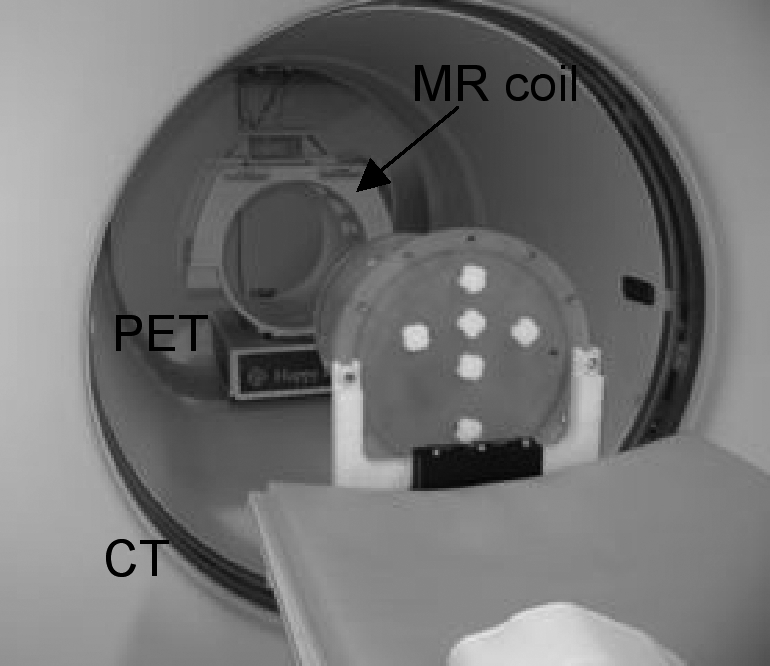
Scan 2 setup. The cylinder phantom was mounted on a bracket suspending it from the end of the patient table. The MRI head coil was positioned in the PET field of view (FOV). The CT scan was performed on the cylinder alone, and then the cylinder was moved into the PET FOV, inside the MRI head coil. Another PET scan was acquired after removing the head coil to obtain scan 3.
Each PET scan was 15 min in duration. Image reconstruction was performed two ways: 3D reprojection with 6.4 mm Hanning filter cutoff, axial 6.5 mm ramp cutoff, and OS-EM with 35 subsets, 6 iterations, and a 6 mm Gaussian postfilter.
Activity concentrations in the cylinder phantom images were taken from a cylindrical volume of interest (VOI), 5 cm thick, 11.2 cm diameter, centered in the cylindrical phantom.
MRI torso surface coil
The torso phantom contained its spine insert (solid PTFE), lungs (foam beads), and liver (water-filled). Each of these inserts contained no radioactivity. The main chamber of the torso phantom was filled with approximately 4 kBq∕ml of 18F solution. The cardiac insert was not present.
We scanned the torso phantom with torso coil on the DSTE PET∕CT scanner: once with both posterior and anterior components of the torso coil attached to the anthropomorphic phantom, and once with only the posterior component. These scans were performed with the same surface coil components present in the CT scan and the PET scan. Again PET acquisition duration was 15 min, and images were reconstructed using the same techniques as for the cylinder phantom within the head coil.
Activity concentration in the torso phantom was measured from a VOI placed on a single slice within a uniform portion of the phantom.
We used our clinical default CT-AC scan protocol for each phantom: helical mode pitch of 0.9375, 140 kVp, 190 mAs, and 5 mm slice thickness. This is a nondiagnostic protocol used for purposes of PET AC and fusion with the PET emission image.
Artifacts due to imprecise AC were evaluated, and activity concentrations measured from the resulting scans were compared to the known values.
RESULTS
Simulations
Results of the two-dimensional simulations of the cylinder and head coil object are shown in Fig. 3. Attenuation artifacts associated with the head coil are seen in both the reconstructed MR-AC and CT-AC emission images. Moderate intensity gradients are also seen [Fig. 3f vertical]. Using MR-AC resulted in an under-estimation of phantom activity level, and using the CT-AC over-estimated activity (image profiles in Fig. 3). Quantitative errors in the simulations depended on coil thickness; over- and under-estimation was approximately 5 and 10%, respectively, in the case shown.
Transmission images of phantoms with coils
Attenuation images of the phantom-plus-RF coil objects measured with both 511 keV transmission and CT scans are shown in Fig. 4. CT images are shown in Hounsfield units (HU), and CT-AC and 511 keV transmission images are shown in (1∕cm) units of linear attenuation coefficients. High-density components in the coils caused streaking artifacts in CT images. These streaks persisted in CT images converted for PET-AC. Details of the coil element makeup, and the loss of detail due to the conversion to CT-AC, are shown in Fig. 4b. The corresponding voxel values in the CT-AC are an average of the different material components seen in the CT [e.g., Fig. 4b left vs Fig. 4b center]. Specific details of the conversion between acquired CT image and CT-AC image are not known (i.e., this process is typically proprietary to each scanner). Transmission scans acquired with 511 keV photons were artifact-free. The partial volume effect is evident in the 511 keV transmission image [Fig. 4b right image]. Regions of interest (ROIs) used to extract linear attenuation coefficients are shown on the CT images in Fig. 4 (CT images).
Figure 4.

(a) Cylinder phantom and head-coil. Left: high-resolution CT image (120 kVp, 168 mAs); Center: CTAC (140 kVp, 190 mAs); Right: 511 keV transmission image (68Ge). Right-hand color bar applies to center and right images. (b) Details of images in (a): close view of one of the upper head-coil elements; left-to-right corresponding to images above. Right: Profiles of the CTAC and 511 keV transmission images [LAC = linear attenuation coefficient. Horizontal and vertical profiles through the center of the images as indicated by edge hash marks on images in (a)]. (c) Torso phantom and coil, from left-to-right: high-resolution CT, CTAC with both coil elements, CTAC with bottom element only, 511 keV transmission. Right-hand color bar applies to three rightmost images. The 511 keV transmission images contained 480M and 700M corrected counts in the cylinder image and torso image, respectively.
Removing the anterior component of the torso coil prior to CT scanning reduced the streak artifacts [Fig. 4c]. From these images, it can be seen that the variation of linear attenuation coefficient due to the CTAC streak artifacts is far less than due to random noise in the 511 keV transmission image. The coefficient of variation (COV = standard deviation divided by mean) for ROIs drawn in the uniform water portion of the torso CTAC is <1% with one or both coil components, whereas COV ∼15% in a similar ROI of the 511 keV transmission image. While streak artifacts are very small, they are not random.
Linear attenuation coefficients (μ) from the 511 keV and CT-AC transmission images are given in Table Table I.. Values from the CT scans have been converted from CT energies to 511 keV using the standard conversion method used clinically.20
Table 1.
Linear attenuation coefficients.
| Image region | 511 keV μ (1∕cm) | CTACμ(1∕cm) |
|---|---|---|
| Cylinder phantom and head coil | ||
| Air | −0.0009 | 0.0003 |
| Water (uniform) | 0.0933 | 0.0932a |
| Water (artifact) | N∕A | 0.0924 |
| Coil-1 | 0.1038 | 0.1534 |
| Coil-2 | 0.1116 | 0.1543 |
| Coil-3 | 0.1034 | 0.1536 |
| Torso phantom and torso coil | ||
| Water | 0.0911 | 0.0933 |
| Spine insert | 0.1630 | 0.1437 |
| Coil-1 (anterior) | 0.1066 | 0.1604 |
| Coil-2 (anterior) | 0.0890 | 0.1595 |
| Coil-3 (posterior) | 0.1001 | 0.1552 |
| Coil-4 (posterior) | 0.1012 | 0.1569 |
The linear attenuation coefficient of water measured using CT without the MR coil present was 0.0931∕cm.NOTE: Coil ROIs shown on Fig. 4 are only for display; actual ROIs used for analyses were smaller than coil structure.
PET emission images: Uniform cylinder
Figure 5 shows PET emission images of the uniform cylinder from scans 1, 2, and 3 described in the Methods section. Transaxial slices were summed to a slice thickness of 5 cm and presented using a color scale to emphasize artifacts in scans 1 and 2 relative to the reference scan. Artifacts within the emission object are less evident when viewing singles slices (3.3 mm thick) using a gray-scale color table. Activity ghosting is seen within the coil when the coil was present in the CT-AC [scan 1, Fig. 5a]. Figure 5e shows the analytical reconstruction for comparison to the simulation results shown in Fig. 3 [cf. Fig. 3d].
Figure 5.

PET emission scans of the cylinder phantom with and without the head coil. (a) Scan 1, CTAC: the head coil was present in the AC scan as well as the emission scan. (b) Scan 2, MRAC: the head coil was not present in the AC scan but was present in the emission scan. (c) Scan 3, reference: no coil in either emission or transmission scan field of view. Images in (a)–(c) are 5 cm thick slices of the OS-EM reconstructions. (d) Profiles through each of the images shown in (a)–(c). (e) The 3-D reprojection reconstruction (3DRP) of scan 2, also 5 cm thick, showing relative agreement with the simulation conducted earlier [compare Fig. 3d].
PET emission images: Torso
PET emission images of the torso phantom and one or both components of the MR torso coil are shown in Fig. 6. No significant qualitative effects were observed in either case. However, there were quantitative errors in these images, as discussed below (Table Table II.).
Figure 6.

(a) PET emission image of the anthropomorphic phantom with both components of the MR torso coil; AC of this image was generated using the CTAC image with both coil components. (b) PET emission image of the same phantom but with only the posterior component of the MR coil present in each the PET and CT scan. Images from an analytic reconstruction method are shown (3-D reprojection). This reconstruction method highlights emission artifacts seen outside the emission object and demonstrates the absence of major streak artifacts inside the emission object.
Table 2.
Quantitative recovery in PET scans containing MR coils.
| Scan #. Description | VOI mean (kBq∕ml) | VOI StDev∕mean(%) | True Act. Conc. (kBq∕ml) | %difference(VOI-true)∕true |
|---|---|---|---|---|
| Scan 1: Head coil in PET and CT (CT-AC) | 3.14 | 4.2 | 2.45 | +28.1% |
| Scan 2: Head coil in PET only (MR-AC) | 2.75 | 4.2 | 3.38 | −18.6% |
| Scan 3: Coil not present (reference scan) | 3.14 | 3.0 | 3.04 | +3.3% |
| Torso, both coil components (CT-AC) | 4.4 | 11.4 | 5.46 | −19.4% |
| Torso, bottom coil component (CT-AC) | 3.8 | 10.5 | 4.84 | −21.5% |
| Torso, no coil (reference scan) | 3.3 | 14.7a | 3.05 | +8.2 |
Shorter acquisition time (10 vs 15 min.) and lower activity relative to scans with coil components.
Quantitative results
Mean activity concentrations measured from the PET images are given in Table Table II. and compared to known values. The approximate size and location of the VOI used to calculate mean activity concentration from the torso phantom is seen on Fig. 4 in the high-resolution CT image of the torso phantom. The VOI used for the cylinder is not seen in the figure; rather, a centered cylindrical VOI was used.
DISCUSSION
In this work, we calculated (through analytic simulations) and measured PET activity concentration recovery accuracy when attenuation from two common MR surface coil designs was ignored or corrected for using conventional CT-AC methods. We performed PET AC using an attenuation image that contained the object being imaged, but that lacked the MR surface coils, as in the scenario where an MRI would be used for PET-AC. We also performed PET-AC using a CT scan that contained surface coils, including the associated metal streak artifacts. Image quality and artifacts and quantitative accuracy were compared for each of these PET-AC methods.
Investigators have explored the use of MRI-based attenuation correction for PET, akin to using the CT image for PET AC in combined PET∕CT.10 There are a number of challenges to MR-AC, and the majority of previous work has focused on the conversion of MR images and voxel values to attenuation coefficients for PET-AC, which has proven challenging, as MRI voxel values do not correspond to a physical parameter readily used as a surrogate for attenuation of 511 keV photons. An additional challenge is the presence of the MR surface coil; the coil attenuates PET data but does not appear in the MR image. As such, an AC map derived purely from an MRI will not be complete because it lacks the surface coil structure that also causes attenuation.
Alternatively, with an appropriately registered patient table, MRI can be combined with PET∕CT in a separate suite, in which case CT-AC could be used for the PET image. This approach could allow investigation of clinical uses of (serial) MR∕PET by investing in a specialized coregistered patient table, without need for new hybrid scanners per se. Combined MR∕PET∕CT does not take advantage of the potential to reduce radiation dose by replacing CT-AC with MR-AC. This serial approach is also possible with PET scanners that use 511-keV (or 662-keV) transmission sources for AC. This AC method has the advantage of energy-appropriate attenuation coefficient measurement, inherently matched emission∕transmission spatial resolution, and lower dose than CT-AC. The main disadvantages are longer scan time and high-noise AC map.
In the case of either integrated or serial combined MR∕PET, removing MR surface coils between MR and PET scans in a combined imaging protocol would likely sacrifice image registration. Leaving the MR surface coil on the patient during PET scanning will result in additional attenuation and scatter of the PET signal due to the presence of the coil. In the case of combining MRI and PET∕CT, and using CT-AC, the challenge includes the high-density materials within the MR coils, the attenuation properties of which are poorly measured by CT.
Analytic simulations of the PET data acquisition and reconstruction processes were conducted with an idealized model of a segmented head coil. When the simulated data were reconstructed without correcting for the attenuation of the head coil, only minor artifacts appeared inside the uniform cylinder emission object [Fig. 3d], but significant artifacts were seen outside of the emission object in areas corresponding to the locations of the coil parts. This is consistent with the study of Bai et al., which showed that attenuation artifacts are localized to the region of mismatch.21 These artifacts appear when using filtered back-projection reconstruction. Iterative reconstruction algorithms suppress most of the artifacts, as these were related to undershoot effects (Fig. 5). Quantitative analyses of the head simulations gave a negative bias of 8%–25% in the reconstructed images, depending on coil thicknesses of 5–15 mm in the model. A negative bias result directly follows from omitting corrections for attenuation present in the emission acquisition (simulations of the head model were not shown).
MRI surface coils are available in a variety of sizes and shapes. MRI head coils are commonly bulky molded plastic that houses the active RF receive circuitry. Despite the relatively large housing (from a PET imaging point of view), they are predominately plastic with moderate attenuation for 511 keV photons and rigid in form. This makes head coils more amenable to attenuation correction using a template approach in which a previously acquired scan of the coil can be inserted into an attenuation map retrospectively.11, 15 Many surface coils designed for other parts of the body are flexible, conforming to the surface of the patient. This situation is much more difficult to treat with a template because the active components of the coil can be in different position relative to each other, meaning a previously acquired scan may not match the distribution of attenuating material in a patient scan. We used one rigid head coil, and one flexible torso coil in our analyses. Using similar but distinct MR head coils, our results were similar to those of Delso et al.15 in that they reported a 17% reduction in total true coincidence counts due to the coil, and we found an 18.6% underestimation of activity concentration due to neglecting the coil attenuation.
CT scanners are not optimized for imaging metal objects, such as are present in MR surface coils. The high atomic number materials cause streaking artifacts in CT images (Fig. 4), and it is difficult to accurately estimate the associated high attenuation coefficients needed for PET attenuation correction. Table Table I. compares linear attenuation coefficients (μ) of the MR coils measured by 511 keV photon transmission and by a conventional PET CT-AC protocol. The linear attenuation coefficient of metal components of the coils measured by CT was 40%–50% higher than the equivalent measured with the 511 keV transmission source. While we do not know the details of the MR coil internal circuitry (metal components), it seems reasonable to assume that the 511 keV transmission scan is a better estimate than the CT-derived value, leading us to believe that the CT scan is over-estimating the attenuation of these coil components.
The CT streak artifacts persisted after conversion for PET-AC (Fig. 4). The PET images of the uniform cylinder showed little qualitative degradation relative to the streaks apparent in the CT images. Figure 5 shows the cylinder phantom reconstructed using the CT-AC of the head coil [Fig. 5a], and when omitting AC for the coil [Figs. 5b, 5e]. Modest artifacts are seen in the scan 2 images with no head coil AC. Modest artifacts on the scan 1 image with CT-AC are more random in nature, and include erroneous activity at the location of the coil [Fig. 5a]. This could be due to the scatter estimate not accounting for the presence of the scattered photons originating in the coil.
Removing the anterior component of the separable torso coil reduced the CT streaking artifacts. Removing part of the coil is an option for combined MR-PET when one of the coil components can be removed without moving the patient and sacrificing MR-PET patient alignment. However, for the coil tested here, removing the anterior portion had little if any effect on the resulting anthropomorphic phantom PET emission images, either qualitatively or quantitatively (Fig. 6, Table Table II.). Although the torso coil linear attenuation coefficients were also overestimated by CT (relative to 511 keV transmission, Table Table I.), the torso phantom activity was underestimated. This is likely due to the underestimation of the spine insert linear attenuation coefficient (Table Table I.), which in turn may be due to the conversion from HU to 511 keV linear attenuation coefficients not being optimized for this material.
Quantitative bias was notable when the cylinder images were reconstructed with CT-AC of the head coil, or with no AC of the head coil (Table Table II.). Omitting the coil AC altogether resulted in a 19% underestimation of activity concentration. When the CT-AC of the head coil was used in reconstruction, activity concentration was overestimated by 28%. This may follow from the CT-AC overestimating the attenuation coefficients of the metal components within the coil. Our analytical simulations also predicted these trends.
Some method of estimating the amount of attenuation caused by MRI surface coils in the PET field of view during combined MRI-PET scanning is required to achieve accurate quantitative recovery in the PET images. We found that standard CT-AC technique did not estimate well the attenuation coefficients of metal components in the coils, resulting in a 28% overestimation of activity concentration in the PET image. Possible approaches to improving the PET-AC of MRI coils are
-
(i)
Optimize CT scanning or reconstruction22 technique and conversion of CT-numbers to 511 keV attenuation coefficients for materials in the MR coils.
-
(ii)
Redesign placement and material of MR coil components to mitigate CT artifacts.14
- (iii)
-
(iv)
Generate an MR image of the surface coil using the main excite-receive RF coil within the MR gantry. From this image, convert to linear attenuation coefficients at 511 keV using segmentation or other conversion methods being developed for MR-AC in PET.
Each of these approaches has challenges, some of which are being investigated; for example, new, advanced CT metal artifact reduction methods improve on standard methods;22 also, in addition to template methods, specialized RF head coil designs with attenuating components outside the PET field of view have been used.14 A combination of these approaches may provide the best overall solution.
CONCLUSIONS
Neglecting the attenuation caused by MR surface coils in combined MRI-PET imaging leads to an underestimation bias in measured activity concentration (by 19% in the case of the 20 cm diameter cylinder and Quad Head Coil tested here). Estimating coil attenuation with a conventional CT scan used for PET AC also leads to bias in the resulting PET image; in the case tested here, the CT overestimated attenuation of high-density components within the coil, resulting in a 28% overestimation of activity concentration in the cylinder PET phantom. In each case the qualitative effects of the coil on the PET image were small but noticeable when compared to a reference scan acquired without the presence of the coil. More prominent artifacts were seen in the CT images that contained coils.
We found that removing a portion of the surface coil reduced the streak artifacts in the CT image, but there were no significant changes in the resulting PET image. However, we believe it would be advisable to remove part of a surface coil in cases where this can be done without moving the patient.
ACKNOWLEDGMENTS
This work was supported in part by NIH R01CA074135. The authors wish to thank Pat Smith, Jim Perdue, and Carlos Espinosa for lending the MR surface coils used in this work, and Thomas Beyer, Martin Lodge, and Gaspar Delso for useful discussions.
References
- Weber W., Grosu A., and Czernin J., “Technology Insight: Advances in molecular imaging and an appraisal of PET/CT scanning,” Nat. Clin. Pract. Oncol. 5, 160–170 (2008). 10.1038/ncponc1041 [DOI] [PubMed] [Google Scholar]
- Shao Y., Cherry S. R., Farahani K., Meadors K., Siegel S., Silverman R. W., and Marsden P. K., “Simultaneous PET and MR imaging,” Phys. Med. Biol. 42, 1965–1970 (1997). 10.1088/0031-9155/42/10/010 [DOI] [PubMed] [Google Scholar]
- Garlick P., Marsden P., Cave A., Parkes H., Slates R., Shao Y., Silverman R., and Cherry S., “PET and NMR dual acquisition (PANDA): Applications to isolated, perfused rat hearts,” NMR Biomed. 10, 138–142 (1997). [DOI] [PubMed] [Google Scholar]
- Pichler B., Judenhofer M., Catana C., Walton J., Kneilling M., Nutt R., Siegel S., Claussen C., and Cherry S., “Performance test of an LSO-APD detector in a 7-T MRI scanner for simultaneous PET/MRI,” J. Nucl. Med. 47, 639–647 (2006). [PubMed] [Google Scholar]
- Catana C., Wu Y., Judenhofer M., Qi J., Pichler B., and Cherry S., “Simultaneous acquisition of multislice PET and MR images: Initial results with a MR-compatible PET scanner,” J. Nucl. Med. 47, 1968–1976 (2006). [PubMed] [Google Scholar]
- Raylman R., Majewski S., Lemieux S., Velan S., Kross B., Popov V., Smith M. F., Weisenberger A., Zorn C., and Marano G., “Simultaneous MRI and PET imaging of a rat brain,” Phys. Med. Biol. 51, 6371–6379 (2006). 10.1088/0031-9155/51/24/006 [DOI] [PubMed] [Google Scholar]
- Woody C., Schlyer D., Vaska P., Tomasi D., Solis-Najera S., Rooney W., Pratte J. F., Junnarkar S., Stoll S., Master Z., Purschke M., Park S., Southekal S., Kriplani A., Krishnamoorthy S., Maramraju S., O’Connor P., and Radeka V., “Preliminary studies of a simultaneous PET/MRI scanner based on the RatCAP small animal tomograph,” Nucl. Instrum. Methods Phys. Res. A 571, 102–105 (2007). 10.1016/j.nima.2006.10.039 [DOI] [Google Scholar]
- Schlemmer H., Pichler B., Schmand M., Burbar Z., Michel C., Ladebeck R., Jattke K., Townsend D., Nahmias C., Jacob P., Heiss W., and Claussen C., “Simultaneous MR/PET imaging of the human brain: Feasibility study,” Radiology 248, 1028–1035 (2008). 10.1148/radiol.2483071927 [DOI] [PubMed] [Google Scholar]
- Beyer T., Weigert M., Quick H., Pietrzyk U., Vogt F., Palm C., Antoch G., Muller S., and Bockisch A., “MR-based attenuation correction for torso-PET/MR imaging: Pitfalls in mapping MR to CT data,” Eur. J. Nucl. Med. Mol. Imaging 35, 1142–1146 (2008). 10.1007/s00259-008-0734-0 [DOI] [PubMed] [Google Scholar]
- Hofmann M., Pichler B., Scholkopf B., and Beyer T., “Towards quantitative PET/MRI: A review of MR-based attenuation correction techniques,” Eur. J. Nucl. Med. Mol. Imaging 36, 93–104 (2009). 10.1007/s00259-008-1007-7 [DOI] [PubMed] [Google Scholar]
- Zhang B., Pal D., Hu Z., Ojha N., Guo T., Muswick G., Tung C., and Kaste J., “Attenuation correction for MR table and coils for a sequential PET/MR system,” in 2009 IEEE, Nuclear Science Symposium Conference Record (NSS/MIC), Orlando, Florida: (2009), pp. 3303–3306.
- Hu Z., Ojha N., Renisch S., Schulz V., Torres I., Buhl A., Pal D., Muswick G., Penatzer J., Guo T., Bonert P., Tung C., Kaste J., Morich M., Havens T., Maniawski P., Schafer W., Gunther R. W., Krombach G. A., and Shao L., “MR-based attenuation correction for a whole-body sequential PET/MR system” in 2009 IEEE, Nuclear Science Symposium Conference Record (NSS/MIC), Orlando, Florida: (2009), pp. 3508–3512.
- Keereman V., Fierens Y., Broux T., De Deene Y., Lonneux M., and Vandenberghe S., “MRI-based attenuation correction for PET/MRI using ultrashort echo time sequences,” J. Nucl. Med. 51, 812–818 (2010). 10.2967/jnumed.109.065425 [DOI] [PubMed] [Google Scholar]
- Catana C., Van Der Kouwe A., Benner T., Michel C., Hamm M., Fenchel M., Fischl B., Rosen B., Schmand M., and Sorensen A., “Toward implementing an MRI-based PET attenuation-correction method for neurologic studies on the MR-PET brain prototype,” J. Nucl. Med. 51, 1431–1438 (2010). 10.2967/jnumed.109.069112 [DOI] [PMC free article] [PubMed] [Google Scholar]
- Delso G.,Martinez-Moller A., Bundschuh R., Ladebeck R., Candidus Y., Faul D., and Ziegler S., “Evaluation of the attenuation properties of MR equipment for its use in a whole-body PET/MR scanner,” Phys. Med. Biol. 55, 4361–4374 (2010). 10.1088/0031-9155/55/15/011 [DOI] [PubMed] [Google Scholar]
- DiFilippo F. P. and Brunken R. C., “Do implanted pacemaker leads and ICD leads cause metal-related artifact in cardiac PET/CT?,” J. Nucl. Med. 46, 436–43 (2005). [PubMed] [Google Scholar]
- Lemmens C. et al. , “Impact of metal artefacts due to EEG electrodes in brain PET/CT imaging,” Phys. Med. Biol. 53, 4417–4429 (2008). 10.1088/0031-9155/53/16/013 [DOI] [PubMed] [Google Scholar]
- Lynnerup N., Astrup J., and Sejrsen B., “Thickness of the human cranial diploe in relation to age, sex, and general body build,” Head Face Med. 1, 13 (2005). 10.1186/1746-160X-1-13 [DOI] [PMC free article] [PubMed] [Google Scholar]
- Lynnerup N., “Cranial thickness in relation to age, sex, and general body build in a Danish forensic sample,” Forensic Sci. Int. 117, 45–51 (2001). 10.1016/S0379-0738(00)00447-3 [DOI] [PubMed] [Google Scholar]
- Burger C., Goerres G., Schoenes S., Buck A., Lonn A., and Von Schulthess G., “PET attenuation coefficients from CT images: Experimental evaluation of the transformation of CT into PET 511-keV attenuation coefficients,” Eur. J. Nucl. Med. Mol. Imaging 29, 922–927 (2002). 10.1007/s00259-002-0796-3 [DOI] [PubMed] [Google Scholar]
- Bai C., Kinahan P., Brasse D., Comtat C., Townsend D., Meltzer C., Villemagne V., Charron M., and Defrise M., “An analytic study of the effects of attenuation on tumor detection in whole-body PET oncology imaging,” J. Nucl. Med. 44, 1855–1861 (2003). [PubMed] [Google Scholar]
- Meyer E., Raupach R., Lell M., Schmidt B., and Kachelrieß M., “Normalized, metal artifact reduction (NMAR) in computed tomography,” Med. Phys. 37, 5482–5493 (2010). 10.1118/1.3484090 [DOI] [PubMed] [Google Scholar]