Abstract
Pulsatile flow across two circular cylinders with different geometric arrangements is studied experimentally using the particle image velocimetry method and numerically using the finite element method. This investigation is motivated the need to optimize gas transfer and fluid mechanical impedance for a total artificial lung, in which the right heart pumps blood across a bundle of hollow microfibers. Vortex formation was found to occur at lower Reynolds numbers in pulsatile flow than in steady flow, and the vortex structure depends strongly on the geometric arrangement of the cylinders and on the Reynolds and Stokes numbers.
Keywords: particle image velocimetry, flow visualization, secondary flow, cylinders, membrane oxygenator, respiratory support, mass transfer
1. Introduction
Chronic lower respiratory disease is the third leading cause of death in the United States [1]. For end-stage chronic lung diseases, lung transplantation is the only curative therapy available at this time [2]. The demand for lungs, however, exceeds the donor supply. The wait time for lung transplants is approaching two years, and the wait-list mortality rate is over 20% [3]. Patients waiting for lung transplantation can be temporarily supported by mechanical ventilation or extracorporeal life support. Unfortunately, prolonged use of mechanical ventilation may result in barotraumas, volume traumas, and other injuries to the lungs [4]. Extracorporeal life support can provide pulmonary support for weeks, which allows rest for the natural lungs, resulting in high recovery rates, especially in the case of acute respiratory diseases [5]. Although extracorporeal life support can act as a bridge to recovery, it is complex, costly, and not practical as a bridge to lung transplantation [6].
As a promising alternative, a total artificial lung (TAL) has been designed to provide pulmonary support for patients and to act as a bridge to lung transplantation. Experiments have been shown that TAL can support basal oxygen and carbon dioxide requirements of animals and have had recent preliminary success in a small number of patients as a bridge to transpant [6, 7]. The right ventricle can be utilized to pump blood through a low-resistance TAL. Therefore, the TAL is ambulatory and omits the need for a mechanical pump. Since prolonged use of a mechanical pump and high shear stresses inside the pumps can cause blood cell trauma, the TAL minimizes cell activation [6].
A TAL is composed of miniature fibers with circular cross-section (diameter approximately 300 µm) inside a cylindrical housing with elliptical cross-section. Gas transport in the TAL is achieved by attaching the device to the cardiovascular circulation system and channeling the oxygen-poor blood from the right ventricle across a bundle of cylinder-shaped fibers through which oxygen-rich air flows. The gases are transported through a thick blood film layer in the TALs, which would take considerable time if driven entirely by diffusion. On the contrary, the gases diffuse through a very thin blood film layer in the nature lung and gas transport is achieved [8]. The gas transport in the TAL may be enhanced by the cross-flow mixing of gases and blood in the region downstream of each fiber, which is a result of the secondary flow that is generated by the oxygen-poor blood flowing across the fibers. The cylinder-shaped fibers inside a TAL are in the environment of low-to-moderate-Reynolds number (Re = 0.1 to 10), pulsatile flow since the TAL employs right ventricle as the blood pump. Understanding and improving TAL gas exchange requires an understanding of the velocity around the cylindrical fibers. Although steady flow past cylinder arrays has been studied extensively in the context of heat exchangers [9], the pulsatile flow past cylinders has received much less attention. In addition, most related previous transient investigations focused on vortex shedding and oscillatory motion of a cylinder within an otherwise stationary fluid. These flows are usually of higher Reynolds numbers (Re > 20) [10–12] and are not applicable to TAL (lower Reynolds number). There has been recent interest in fundamental heat transfer from pairs of cylinders in a variety of conditions [13, 14]
Unlike traditional oxygenators, which employ an external pump to drive the blood flow, a TAL utilizing the right ventricle as a blood pump should be designed to have low flow resistance. Additionally, the TAL impedance needs to be low in order to ensure satisfactory right heart function [15–17]. Nonetheless, a TAL is usually designed with the miniature fibers packed close together to produce a small TAL with large surface area, which may increase the flow and impedance and pressure drop. Therefore, an essential design consideration is optimizing the fiber sizes/arrangement and blood flow conditions in order to achieve sufficient TAL gas exchange while maintaining physiologically acceptable TAL impedance.
Motivated by TAL designs, the effects of pulsatile flow on flow structures and mass transfer around circular cylinders have been studied numerically (Re = 1–10, Re > 5 for most cases) [18–22]. It was suggested that mass transfer may be increased by altering the geometry of the cylinders, the frequency of the pulsatile flow, and the functional form of the velocity. Nevertheless, the results of the previous research showed discrepancies. The mass transfer in TAL has been probed experimentally by Zierenberg et al. [23] who used a bench-top model and monitored the oxygen transfer across a fiber bundle. However, they used a small device that makes the velocity field very hard to examine and investigated only one configuration of the fibers (staggered). Lin et al. [24] presented the first experimental study of vortex formation around a cylinder in pulsatile flow at Re = 1 to 5. It was demonstrated that vortices occur behind the cylinder at low Reynolds number (Re =1) in pulsatile flow, while no vortex was observed in this low Reynolds numbers in steady flow.
The goal of this study is to investigate pulsatile flow and gas transport across cylinders with different geometric arrangements for better optimal design of TAL. We started the study with two cylinders, and investigated the effects of Stokes and Reynolds numbers of the pulsatile flow and the geometry of the cylinder arrangement on vortex formation. To compare the experimental results, we also developed a corresponding finite element model. We were aware that investigation of flow past two cylinders is great simplification of flow in an actual TAL. Nevertheless, how the combination of pulsatile flow and various geometric cylinder arrangements affects the flow is not fully understood. Experimental work that provides detailed flow information is lacking from the literature. This study presents the first experimental investigations of flow structures in pulsatile flow past multiple cylinders at Reynolds numbers applicable to the TAL.
2. Methods
To better understand the flow between the fibers in the TAL, we modeled the fibers with two cylindrical rods and studied the effects of fibers arrangements, Reynolds number, Stokes number, and flow frequency on the flow around the cylinders. The cylinders were arranged with three different geometric patterns: side-by-side, staggered, and tandem; and pulsatile flows with different Reynolds number and Stokes numbers passed across these cylinders. The velocity fields around the cylinders were examined with particle image velocimetry (PIV) method experimentally and compared with the numerical results.
2.1 Experiments
This approach used an experimental setup similar to previous investigation of a single circular cylinder in pulsatile cross-flow [24]. This model was scaled up for easier flow visualization, and the relevant dimensionless numbers were matched to the anticipated range in MC3’s BioLung® (Michigan Critical Care Consultants, Ann Arbor, MI). The cylinders (diameter=500 µm) that represent the fibers inside the TAL are scaled up to about 1.67 times the fiber diameter and positioned in the test section of the water tunnel. The cylinder length to diameter ratio is 100, thus the central portion of the cylinder (86 diameters) can be treated as two-dimensional flow condition since end effects near the wall normally were found within span-wise distance of about seven diameters [25]. The pulsatile flow across the cylinders is generated by controlling the water from and to a reservoir using the linear actuator and four one-way valves. The flow rate is scaled lower (ranged from 0.2 cm/sec to 1cm/sec) to achieve desired Reynolds number (1 to 5).
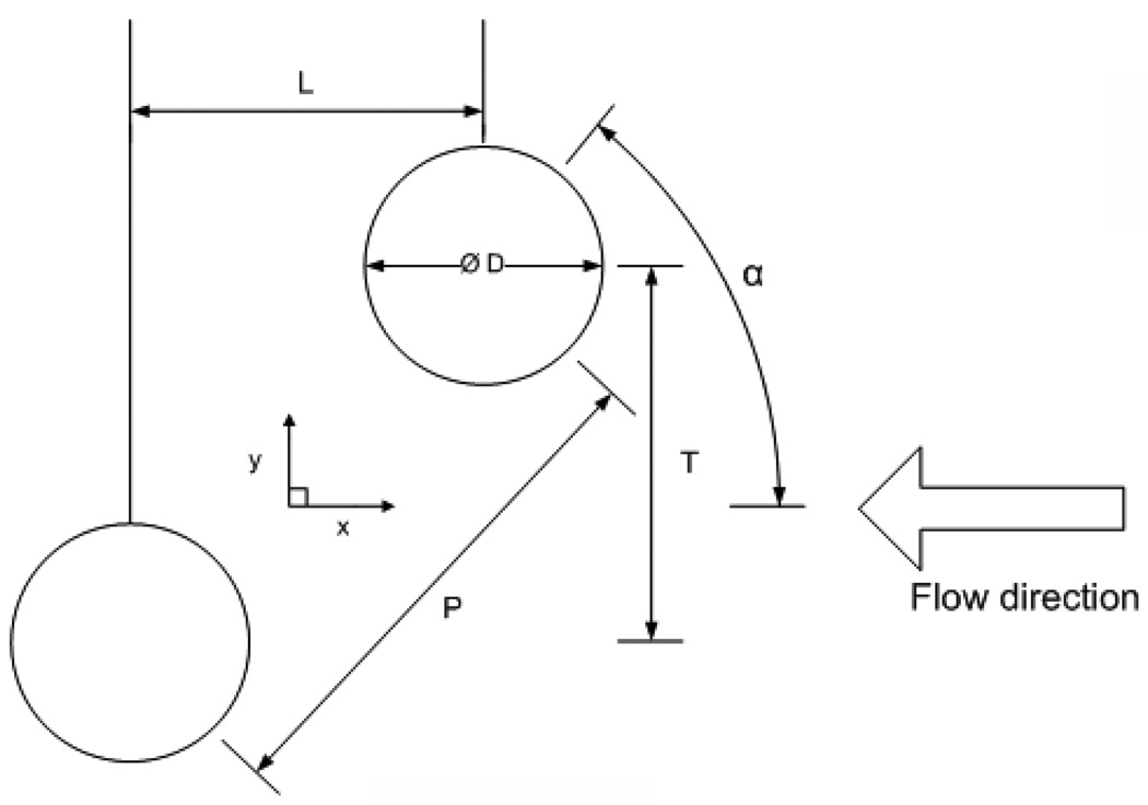
To investigate the fibers geometrical arrangement effects, we started by placing two circular cylinders with different configurations in the test section to model the fibers inside the TAL (Fig. 1).The center-to-center pitch between the cylinders is denoted as P. The distance between the cylinders may also be defined by the longitudinal spacing L and transverse spacing T. The roll angle of the cylinders is denoted as α. The size of the vortices behind the cylinders was measured experimentally at several times during the pulsatile flow cycle. The vortex length is defined by the distance between the center of the cylinder and the end of the recirculation zone, and denoted as Y. The height of the vortices is denoted as X.
Figure 1.
The geometry of the cylinders. The center-to-center pitch between the cylinder is denoted as P. The distance between the cylinders may also be defined by the longitudinal spacing L and the transverse spacing T. The roll angle of the cylinders is denoted as α. The configuration α = 0° is referred as tandem; α = 90° is referred as side-by-side; staggered corresponds to α = 45°.
The fiber bundle inside the TAL is usually constructed by wrapping a flexible fiber mat around a mandrel, which is in the middle of the TAL (the fibers are placed parallel with the mandrel). The fiber matt is comprised of a single row of hollow fibers knitted into a fabric array so that the linear spacing of the fibers along of the mat is uniform. The fiber mat we modeled is Celgard® microporous polypropylene fiber (Celgard® X30-240 Array, fiber outer diameter=300 µm, pore porosity= 40%, Membrana GmbH Co., Wuppertal, Germany), the same fiber that is used in a Biolung® prototype. The fabric density of Celgard® microporous polypropylene fiber is 50 filaments per inch, which makes the ratio of center-to-center distance to fiber’s diameter (P/D, pitch ratio) varies from 1.67 to 2.33. For simplicity, we chose 2 as our pitch ratio. We chose three different arrangements: tandem (α = 0°), side-by-side (α = 90°), and staggered (α = 45°). For each configuration, at least two different frequencies of the pulsatile flow across the cylinders were investigated.
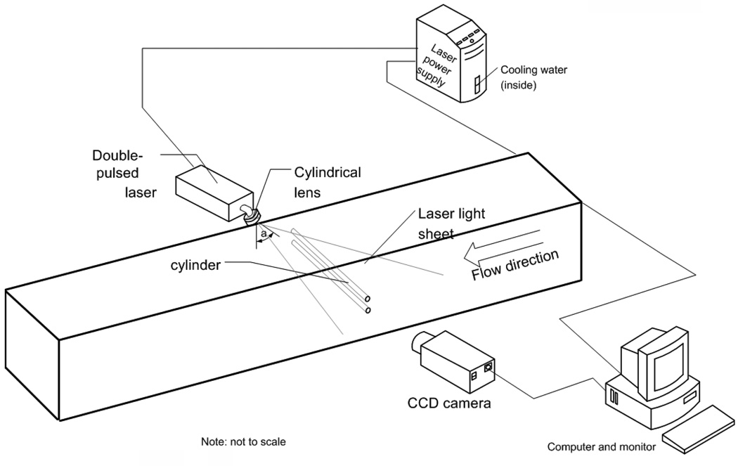
The particle image velocimetry (PIV) method [26] was used to measure the velocity around the cylinder. This technique gives information over global domain, which permits investigation of complex flow fields (as we observed between the cylinders). A schematic diagram of our PIV setup is shown in Fig. 2. The water tunnel was filled with de-ionized water, and was allowed to reach room temperature overnight to avoid thermal effects. The water was seeded with neutrally buoyant hollow glass spherical particles (Borosilicate glass, diameter = 10 µm, density = 1.1g/cm3, Dantec Dynamics Co., Skovlunde, Denmark). These particles were illuminated by a pulsed Nd-YAG laser light (Model: Solo III 15Hz, No: 16155, wavelength 266~1064nm, New Wave Inc., Fremont, CA, U.S.) from the top of the water tunnel. The laser beam passed through a cylindrical lens (Modular-Focus, f=−6mm, Rodenstock Co., München, Germany) and then was shaped into a laser light sheet (less than 1mm in thickness and 100mm in width), which projected from the top of the area with an angle (denoted as a in Fig. 2). This configuration generated shadow of the cylinders in the upstream area. The images of the region of interest were captured by a CCD camera (1280×1024 pixel spatial resolution, Flowmaster 3S, LaVision Inc., Goettingen, Germany), which was positioned perpendicularly to the flow. Each image covered an area approximately 17mm×14mm (~ 28 cylinder diameters in height) within the flow field.
Figure 2.
PIV setup for two cylinders experiments. The vertical laser sheet is projected from the top of the water tunnel at an angle (a) on the interest area. The camera was positioned perpendicular to the laser sheet and parallel to the cylinder.
The successive pairs of single-exposure images were then processed employing PIV software (Davis 6.2, LaVision Inc., Goettingen, Germany). Each of the images was divided into small interrogation areas of 16×16 pixels. The interrogation areas of two different instants were cross-correlated with each other with 50% overlap. The time delay, Δt, between the two images in the pair is very short, such that the particles in the interrogation area have not traveled a large distance, allowing the cross-correlation to be performed. Generally, this time between single-exposure images needed to be adjusted for the specific velocity range of the flow since the flow is time-dependent. This cross-correlation process was repeated for all of the interrogation areas to obtain the velocity vector field over the entire image. A time sequence of the velocity field was obtained repeating this process for subsequent image pairs. For each configuration at a specific time, at least 30 experiments were conducted and 30 pairs of images were obtained.
2.2. Computational Model
Governing Equations
The conservation of momentum and mass of incompressible fluid can be expressed as:
| (1) |
| (2) |
The mass transport is governed by the convection-diffusion equation:
| (3) |
where c is the gas concentration, v is the velocity vector, ν is the kinematic viscosity, p is the pressure, and D is the mass diffusivity. Three important dimensionless parameters govern the flow and mass transport in TAL: Reynolds number, Stokes number, and Schmidt number. These numbers can be expressed as follows:
| (4) |
where U is the mean velocity, d is the fiber diameter, and ω is the frequency of the pulsatile flow. The boundary conditions in non-dimensional forms are:
- Surface of the cylinder: No slip and no penetration
(5) - Free-stream conditions are imposed far away from the cylinder
(6)
The average Sherwood number on the cylinder surface, which represents the ratio of convective to diffusive mass transport, can be defined as:
| (7) |
Numerical Scheme
A finite element formulation based on the Galerkin method is employed to solve the governing equations for unsteady incompressible flows past a pair of cylinders at various Reynolds and Stokes numbers (v8.3.1, ADINA R&D, Inc., Cambridge, MA). Nine node quadrilateral elements with bi-quadratic interpolation functions were utilized in this investigation to discretize the physical domain. These elements were assumed to be fixed in the space. The computational domain included a rectangular cross-section channel to model the test section of the water tunnel. The cylinders were positioned at a distance of approximately 200 cylinder diameters from the channel inlet and entrance and distance of approximately 800 cylinder diameters from the channel outlet. No-slip boundary conditions were applied on the top and bottom walls of the water tunnel as well as the walls of the cylinders. The inlet boundary condition implemented in this investigation was determined from the experiments using a flow sensor (Flo-Sensors, Model 104, McMillan Company, Georgetown, Texas). Due to the small disturbances in the experimental waveform, the least-square method was used to smooth the inlet velocity profile obtained by the flow sensor. The stress tensor was assumed to be zero at the exit of the channel.
Code Validation
The present numerical code was validated by solving flow and mass transport past a circular cylinder at various Reynolds number. Our Sherwood number results were validated against various results reported in the literature [9, 27–29] as shown in Table 1.
Table 1.
Comparison of the average Sherwood number between the present study and those by others published in the literature for the case of steady flow with Sc=1000.
| Re | Present | Zierenberg et al. [39] |
Hilpert [40] |
Zijnen [41] |
Gnielinski [42] |
Sparrow et al. [43] |
|---|---|---|---|---|---|---|
| 5 | 14.04 | 13.43 | 16.93 | 13.8 | 14.85 | 14.03 |
| 10 | 18.85 | 18.46 | 22.11 | 18.92 | 21.00 | 20.13 |
| 20 | 26.91 | 27.37 | 28.87 | 26.18 | 29.69 | 28.99 |
| 30 | 34.74 | 34.20 | 33.75 | 31.78 | 36.37 | 35.94 |
| 40 | 40.61 | 39.40 | 37.70 | 36.52 | 42.00 | 41.88 |
3. Results and Discussion
Enhanced gas transfer inside the TAL is expected due to the secondary flow (vortices) generated behind the fibers. We studied the vortices structure behind the fibers by modeling them with 2 cylinders of different arrangement in different flow conditions experimentally and numerically. The results from both methods follow the same trend with respect to the vortex size (Table 2). The values predicted by the computational model are within 25% of the corresponding measurements, with much closer agreement for most values of Re and Ns. The discrepancy in the results, especially at high Stokes number (Ns = 0.37), may be attributed to the computational model not exactly modeling the conditions of the experiments. For example, a smoothed flow waveform was used in the computational model. The vortices’ sizes vary with cylinders’ arrangements, Reynolds numbers, and Stokes number. Therefore, the fibers’ arrangement and sizes in the artificial lung may play a crucial role in optimizing the design for different patients.
Table 2.
Comparison of the vortices’ sizes between the experimental results and the computational fluid dynamics (CFD) results using three different cylinder arrangements: tandem (α = 0°), staggered (α = 45°), and side-by-side (α = 90°)
| α = 0° | *X/D (PIV) | X/D (CFD) | Error % |
|---|---|---|---|
| Ns=0.18, Re = 1 | 26 | 27.23 | 4.73 |
| Ns=0.18, Re = 3 | 23.04 | 23.32 | 1.22 |
| Ns=0.18, Re = 5 | 20.476 | 19.142 | 6.51 |
| Ns=0.37, Re = 1 | 25 | 19.14 | 23.4 |
| Ns=0.37, Re = 3 | 25.28 | 21.23 | 16.02 |
| α = 45° | X/D (PIV) | X/D (CFD) | Error % |
|---|---|---|---|
| Ns=0.18, Re = 1 | ~23 | 21.4 | 12.6 |
| Ns=0.37, Re = 1 | 21.18 | 17.4 | 17.84 |
| α = 90° | X/D (PIV) | X/D (CFD) | Error % |
|---|---|---|---|
| Ns=0.37, Re = 1 | 23.6 | 22.67 | 3.94 |
| Ns=0.18, Re = 5 | 32–33.1 | 29.65 | 4.4 |
X/D: Ratio of the vortex length to the cylinder diameter
3.1 Side-by-Side Cylinders (α = 90°)
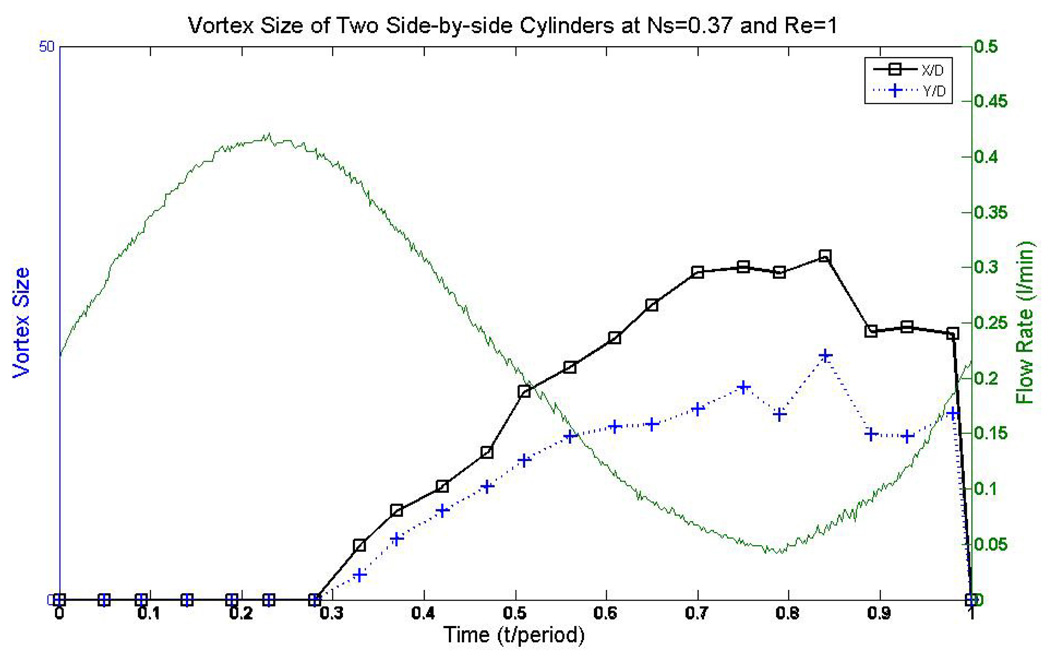
The arrangement of two side-by-side cylinders (α = 90° in Fig. 1) can be considered to be a simplified model of a column of cylinders that is in interference from a neighboring cylinder. In our experiments, the vortices occurred behind two side-by-side cylinders at the low velocity region, and increased their length and height as the velocity decreased (Fig. 3). As the velocity increased, the vortices shrank in size, and both of the vortices disappeared at the peak of the cycle (high velocity). The vortices reappeared as the velocity decreased again and grew in size.
Figure 3.
An example of the variation of vortex size with time under the condition of Reynolds number of 1 and Stokes number of 0.37. The vortices’ size decreased as the velocity increased, and grew as the velocity decreased.
3.2 Staggered Cylinders (α = 45°)
Staggered arrangement of two cylinders (α = 45° in Fig. 1) may be the most common configuration, which is found in many forms in nature and engineering application. This would correspond to a wrapping of the fiber mat in the artificial lung in such a manner that individual fibers are not exactly aligned between layers. This staggering of fibers is likely given the current technique of manually wrapping the fiber mat.
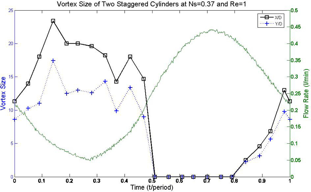
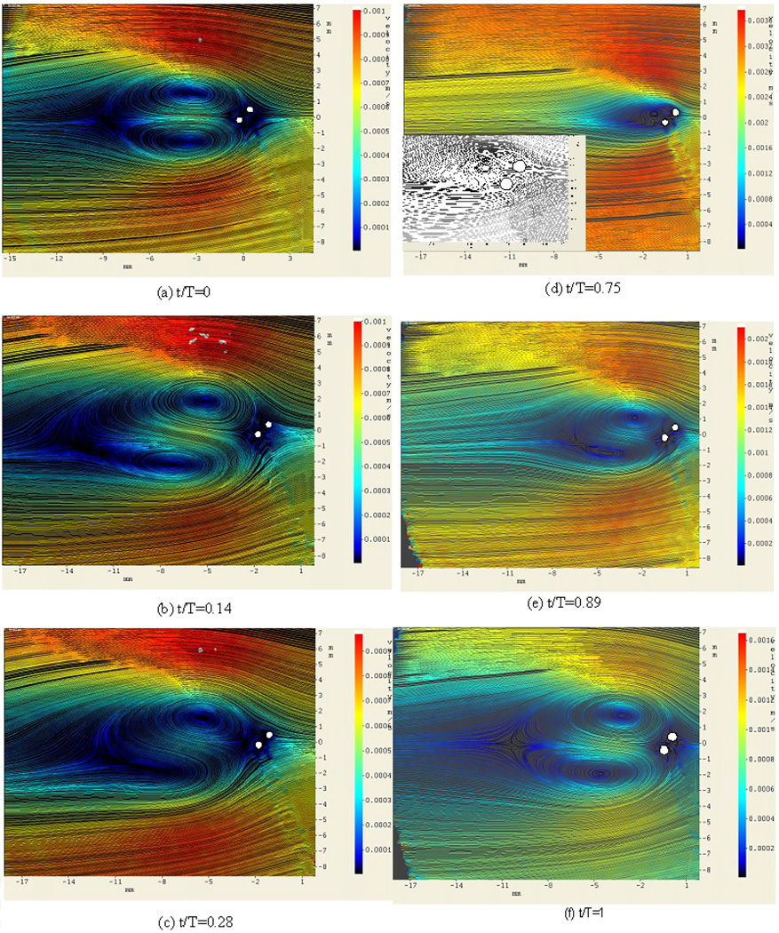
Both the size and the number of vortices behind two staggered cylinders varied during the cycle of the pulsatile flow (Fig. 4), while in other arrangements only the size of the vortices varied. This behavior is evident in Fig. 5, which shows the streamlines around the two cylinders at different times. The cycle started at the decreasing velocity phase. At first, the size of the vortices increased, and then decreased as the time proceeded to the increasing velocity phase. The vortices are asymmetric at the increasing velocity’s phase and the downstream (bottom) vortex became incomplete. Both of the vortices disappeared for a period of time. As the velocity started to decrease again, the upstream vortex (top) was observed first. This vortex grew in size as the velocity kept decreasing; and then the second vortex started forming after the downstream cylinder (the bottom one).
Figure 4.
The transition of vortex size (X/D and Y/D) and structure for two staggered cylinders in pulsatile flow with Re = 1 and Ns = 0.37.
Figure 5.
Streamlines around the two staggered cylinders at various dimensionless times, from the PIV experiments. Note that one cycle of the pulsatile flow occurs over a dimensionless time of one. Inset 5(d) is the enlarged streamlines near cylinders. The flow is from right to right with Re = 1 and Ns = 0.37.
The wake and the shear layer of each cylinder in this arrangement interacted with that of the other cylinder, which makes the flow structure after those two cylinders more complex than the other two arrangements. The asymmetric structure can be explained by viewing the downstream cylinder “squeezes” the streamlines between the two cylinders [30].
3.3 Tandem Cylinders (α = 0°)
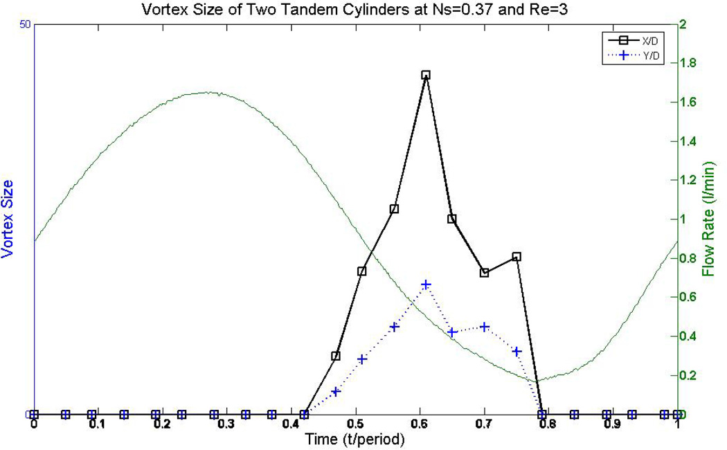
The tandem cylinder arrangement (α = 0° in Fig. 4.) is an idealized model of a row of cylinders in a square multiple cylinder cluster. It provides information on the effects of the upstream cylinder on the downstream cylinder, where the downstream cylinder is in the wake of the upstream cylinder. Flow reversal was observed downstream of the tandem cylinders for Re = 1 and Ns = 0.18. This flow reversal was not observed around a single cylinder that immersed in the same pulsatile flow condition [24]. Vortex size varied during the cycle of the pulsatile flow (Fig. 6). Vortex size decreased as the flow rate increased, disappeared at highest velocity, and reappeared as the flow rate decreased.
Figure 6.
An example of the variation of vortices behind a pair of tandem cylinders, under the condition of Reynolds number of 3 and Stokes number of 0.37. The vortices’ size decreased as the velocity increased, and grew as the velocity decreased.
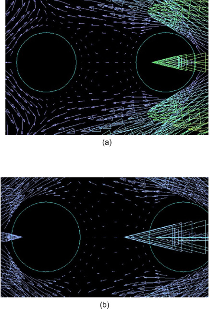
Depending on the Reynolds number, there is a critical spacing of the cylinders L/D (where L is the longitudinal distance between centers of the cylinders and D is the diameter of the cylinder) in steady flow [31]. Below a threshold value of L/D, no vortex occurs in the gap region for tandem arrangement. In our model, L/D=2. From the PIV results, no vortex was observed between the gap between the tandem cylinders. However, the computational results revealed a pair of very weak vortices between the cylinders during the deceleration phase of the cycle (Fig. 7).
Figure 7.
The numerical results of a pair of weak vortices between the tandem cylinders during the deceleration phase of the cycle for (a) Re = 1, Ns = 0.37; (b) Re = 3, Ns = 0.37.
The computationally predicted fluid speed in the gap between the cylinders was less than 0.01 cm/s, which is considerably smaller than the cross-sectional average velocity in the water tunnel. A considerably longer Δt would be required to detect motion of the particles for PIV in this region than in the rest of the flow field. At this small fluid velocity, Brownian motion of the particles for PIV can play a significant role, and interfere with the particle movement in the PIV method. Additionally, the shadow from the upstream cylinder and the reflection from the cylinder might make any vortices in this gap difficult to detect.
3.4 Effects of Cylinder Arrangement
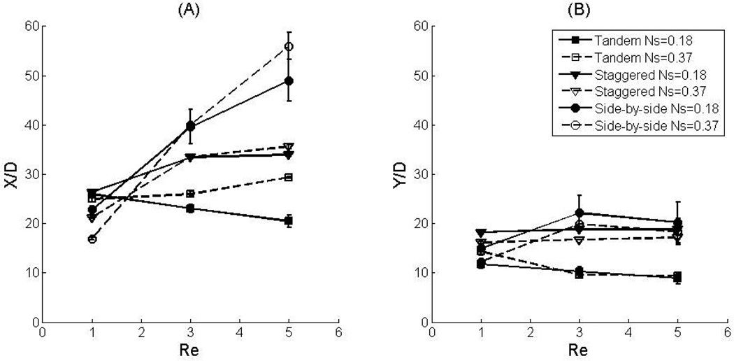
The sizes of the vortices at the beginning of the pulsatile flow cycle were measured experimentally for pulsatile flows of Re = 1, 3, 5 and Ns = 0.18, 0.37 past tandem, staggered, and side-by-side cylinder arrangements (Fig. 8). The length of the vortex (X/D) is larger in the side-by-side cylinder arrangement than in the other two arrangements when Reynolds number is larger than 3. The height of the vortices (Y/D) also has the same trend, except the case of side-by-side arrangement at Re = 5, Ns = 0.37. We note that at the time in the cycle when the vortex was the largest for the side-by-side cylinder arrangement, the vortex length extended past the observation area in some of the experiments, requiring the overall length of the vortex to be approximated from the available images for Re = 5 and Ns = 0.37. The irregular trend in vortex length for the side-by-side cylinder arrangement at Re = 5, Ns = 0.37 may be due to measurement and estimation errors.
Figure 8.
Comparison of the vortex length (a) and height (b) between 2 cylinders with different arrangements.
As described previously, there is a critical spacing between the cylinders. If the spacing between the two cylinders less than a threshold value, the two cylinders may act like a hypothetical “single bluff body” whose imaginary surface is formed by a bounding streamline that encompasses the two cylinders and some region of fluid. Two tandem cylinders spaced closer than this threshold act like single bluff body. However, the threshold value is a function of Reynolds number, which implies that for a pulsatile flow where the velocity changes with time, this value may be different from the value of steady flow. The side-by-side arrangement has relatively larger “projective diameter” compared to the other cylinder arrangements, which may generate larger recirculation. The tandem cylinder arrangement has the smallest projective diameter, thus the size of the vortices is the smallest of the three different arrangements.
3.5 Effects of Reynolds Number and Stokes Number (Effects of Flow Condition)
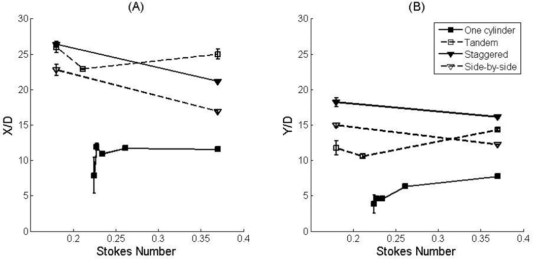
Vortex size increased with Reynolds number in the side-by-side and staggered cylinder arrangements (Fig. 8). This may be due to the increased contribution of inertia at higher Reynolds numbers. The vortex length in the tandem cylinder arrangement increased with Re at Ns = 0.37, but decreased with increasing Re for Ns = 0.18. The vortex height in the tandem cylinder arrangement decreased with increasing Re. This complicated relation between the Reynolds number and the vortices might be contributed to the wake and shear layer effects from the upstream cylinder. For staggered and side-by-side cylinder arrangements, vortex size decreased as the Stokes number increased (Fig. 9). For the tandem cylinder arrangement, a simple relationship between vortex size and Stokes number is not obvious.
Figure 9.
Vortex length (a) and vortex height (b) vs. Stokes number. For staggered and side-by-side arrangement, the size of the vortices decreases as the Stokes number increases.
Besides vortex size difference in the beginning of the cycle, we noted that the vortex size vitiates in the pulsatile flow (changing Re during the period) cycle. The vortices disappeared during the increasing Re of the flow. This on-and-off feature is unique in the pulsatile flow, and not was observed in steady flow (data not shown). On-and-off vortex formation and variation of vortex size may help with transporting gases in TAL. A further investigation of relation between on-and-off vortex formation and gas transfer is needed.
3.6 Effect of the Cylinder Geometric Arrangements on the Mass Transport
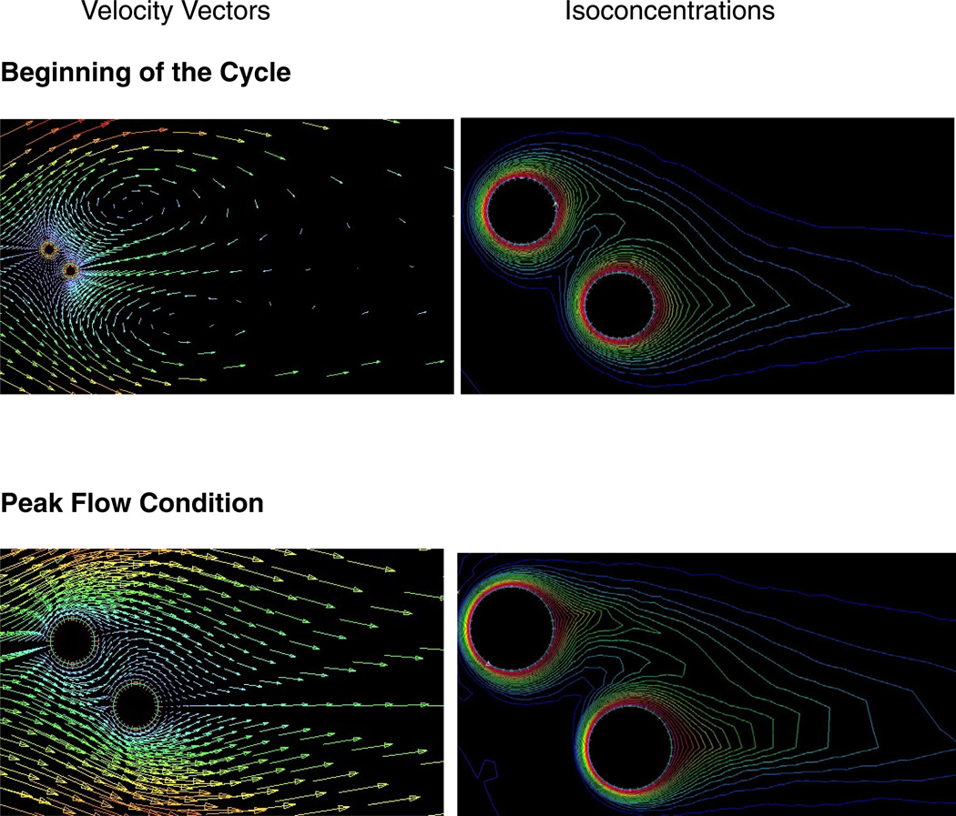
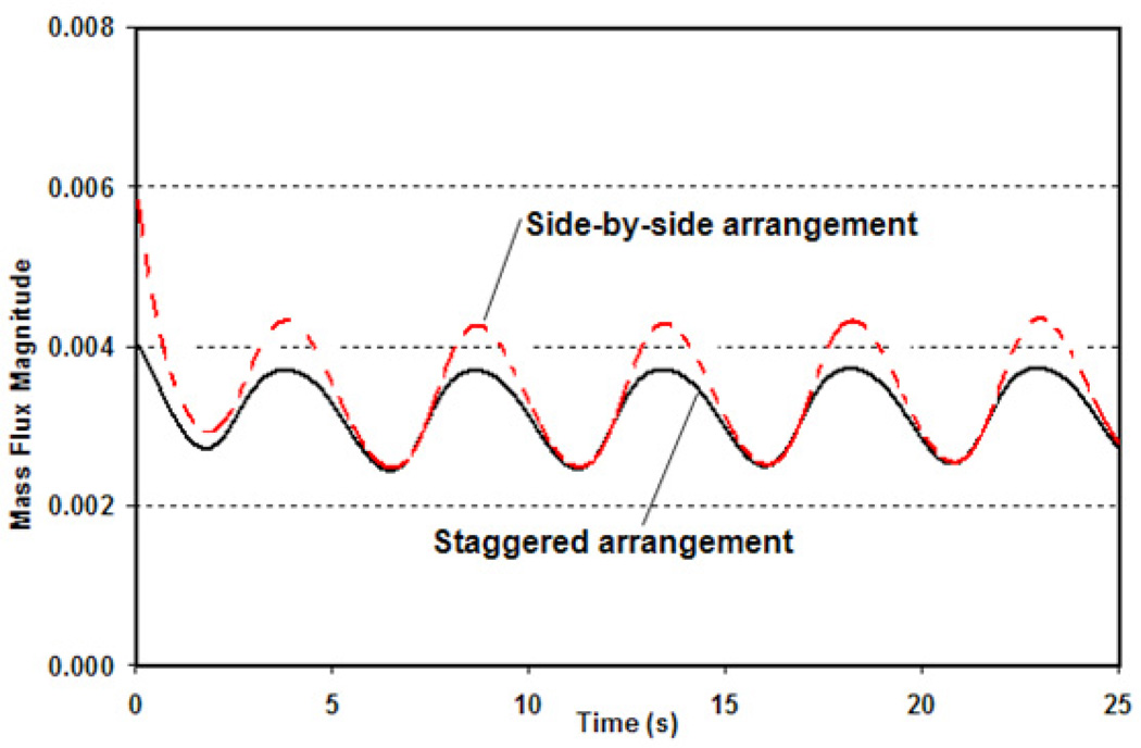
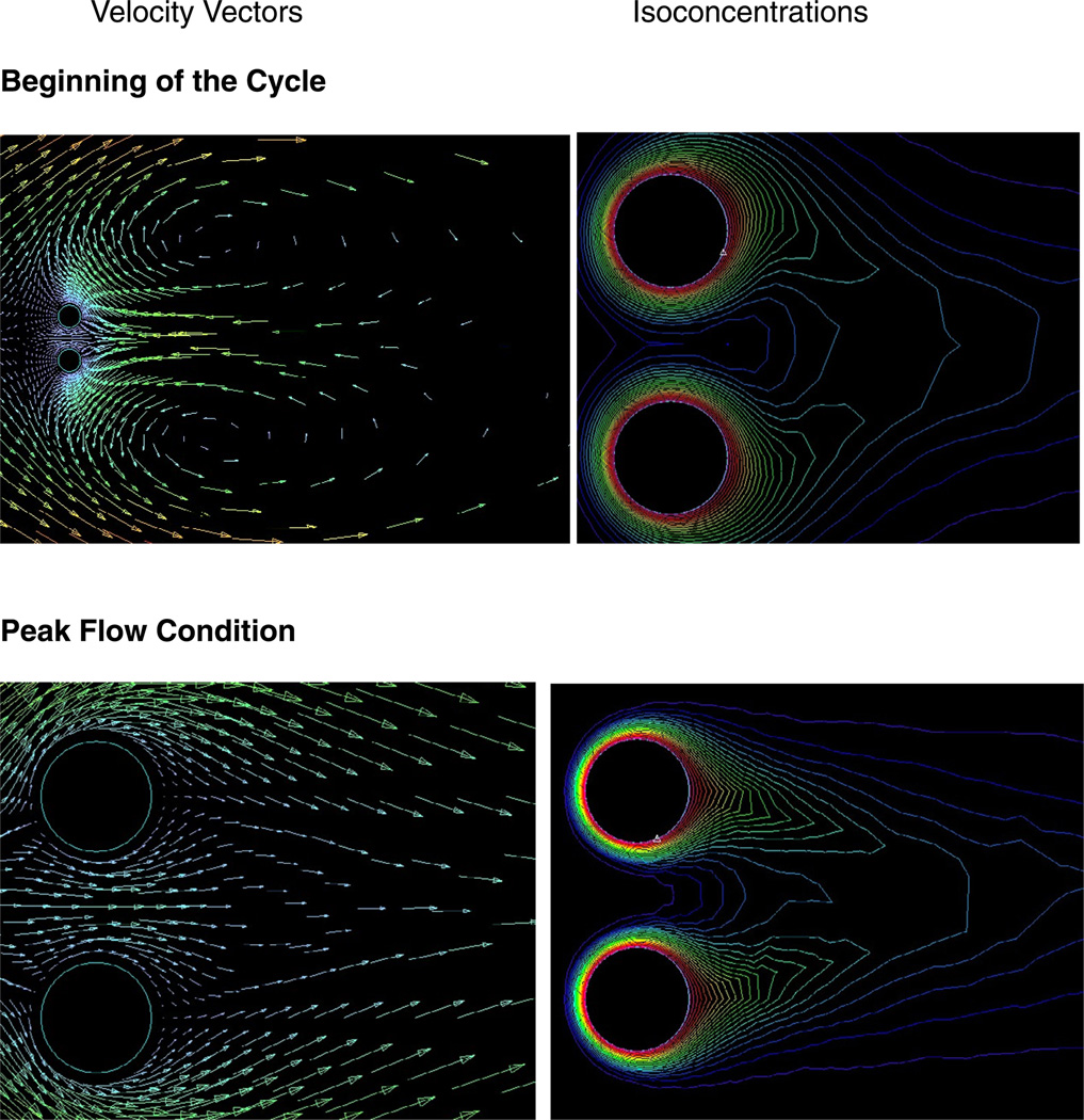
The effect of the cylinder geometric arrangements (staggered arrangement and side-by-side arrangement) on mass transport is illustrated in Figs. 10–12. The values of the iso-concentration lines decrease with increasing distance from the surface of the cylinder, and strongly affected by the geometric arrangements of the cylinders. This is clearly seen in Figure 12, which represents the temporal variation of the maximum local mass transfer. According to our results, side-by-side arrangement is found to have higher maximum local mass transfer than staggered arrangement (2 cylinders).
Figure 10.
Velocity vectors and isoconcentrations around the two staggered cylinders for various periods of the cycle.
Figure 12.
Comparison of the maximum mass flux on a cylinder between staggered and side-by-side arrangements.
3.7 Other Experimental Effects and Limitations
The asymmetric flow structure after the cylinders can be attributed to the following perturbation sources: non-uniform oncoming flow, presence of surface roughness, and the running condition of the experiment [32]. The flow was close to uniform near where the cylinders were placed. The slight disparity in the trend of the vortex size may be is caused by the inconsistency of the velocity profile and the error of the measurement. However, the flow conditions might be disturbed by the experimental environment. Moreover, the roughness of the cylinders may be the reason of the irregular trend of the vortices’ size.
In this investigation, a number of simplifying assumptions were made, such as using a Newtonian fluid, considering only two cylinders, and evaluating only three cylinder arrangements. The choice of conditions to examine was motivated by the desire to examine a tractable problem in which the effects of a number of parameters could be examined. There are practical limitations of multiple cylinder experiments. While the computational model is relatively straight forward, the corresponding experiments for an array of cylinders are challenging because the cylinders on the outer regions of the array shadow the interior making it difficult to introduce the laser sheet into the interior of the array for PIV. PIV measurements become difficult when many cylinders are present because the shadow cast by the cylinders on the outside of the array prevents measurement of the velocity field near the interior of the array. The effects of neglected aspects, such as the non-Newtonian properties of blood, can be investigated in future work. Likewise, future studies are needed to examine gas exchange in these configurations. Nevertheless, this study represents a first step in experimentally examining pulsatile flow around multiple cylinders and confirming the ability of computational models to predict the resulting behavior.
4. Conclusions
This study presents the first experimental investigations of flow structures in pulsatile flow past multiple cylinders at Reynolds numbers applicable to the TAL. Pulsatile flows at Reynolds numbers of 1 to 5 and Stokes numbers of 0.17 to 0.38 across three different cylinder configurations, tandem (α=0°), staggered (α=45°), and side-by-side (α=90°), were examined. A corresponding computational model was developed, and the results were consistent. The findings of this study are summarized as follows: (1) In pulsatile flow, vortices form behind the two cylinders at Reynolds numbers that are too low for vortex formation in steady flow. This implies that vortices may form in the TAL in low Re, (2) the vortex size is a function of Reynolds number, Stokes number, and the cylinder configuration, (3) larger Reynolds number, Stokes number, and larger streamline curvature can introduce larger vortices, which may enhance mass transfer, and (4) the arrangement of fibers within the TAL is expected to influence flow. Some arrangements may create instability and asymmetry of the vortices, which may be beneficial for the gas transfer. However, the geometric configuration can affect TAL impedance and gas exchange, two competing criteria that must be optimized.
Figure 11.
Velocity vectors and isoconcentrations around a pair of side-by-side cylinders for various periods of the cycle.
Acknowledgements
This work was supported by NIH grants R01HL69420 and R01HL089043.
Nomenclature
- c
concentration
- D
diffusivity
- L
longitudinal spacing
- n
normal
- Ns
Stokes number
- P
pitch
- p
pressure
- PIV
particle image velocimetry
- Re
Reynolds number
- Sc
Schmidt number
- Sh
Sherwood number
- T
transverse spacing
- TAL
total artificial lung
- t
time
- U
free stream velocity
- u
horizontal velocity component
- v
vertical velocity component
- v
velocity vector
- X
vortex length
- x
horizontal spatial coordinate
- Y
vortex height
- y
vertical spatial coordinate
Greek symbols
- α
roll angle
- θ
angular coordinate
- ν
kinematic viscosity
Footnotes
Publisher's Disclaimer: This is a PDF file of an unedited manuscript that has been accepted for publication. As a service to our customers we are providing this early version of the manuscript. The manuscript will undergo copyediting, typesetting, and review of the resulting proof before it is published in its final citable form. Please note that during the production process errors may be discovered which could affect the content, and all legal disclaimers that apply to the journal pertain.
References
- 1.Minino AM, Xu JQ, Kochanek KD. In: Deaths: Preliminary Data for 2008. N.V.S. Reports, editor. Hyattsville, MD: National Center for Health Statistics; 2010. [PubMed] [Google Scholar]
- 2.Nathan SD. Lung transplantation - Disease-specific considerations for referral. Chest. 2005;127(3):1006–1016. doi: 10.1378/chest.127.3.1006. [DOI] [PubMed] [Google Scholar]
- 3.Haft JW, Griffith BP, Hirschl RB, Bartlett RH. Results of an artificial-lung survey to lung transplant program directors. Journal of Heart and Lung Transplantation. 2002;21(4):467–473. doi: 10.1016/s1053-2498(01)00378-3. [DOI] [PubMed] [Google Scholar]
- 4.Kolobow T. Volutrauma, barotrauma, and ventilator-induced lung injury: Lessons learned from the animal research laboratory. Critical Care Medicine. 2004;32(9):1961–1962. doi: 10.1097/01.ccm.0000134405.71890.3a. [DOI] [PubMed] [Google Scholar]
- 5.Jurmann MJ, Haverich A, Demertzis S, Schaefers HJ, Wagner TOF, Borst HG. Extracorporeal membrane-oxygenation as a bridge to lung transplantation. European Journal of Cardio-Thoracic Surgery. 1991;5(2):94–98. doi: 10.1016/1010-7940(91)90006-6. [DOI] [PubMed] [Google Scholar]
- 6.Zwischenberger BA, Clemson LA, Zwischenberger JB. Artificial lung: progress and prototypes. Expert Rev. Med. Devices. 2006;3(4):485–497. doi: 10.1586/17434440.3.4.485. [DOI] [PubMed] [Google Scholar]
- 7.Camboni D, Philipp A, Arlt M, Pfeiffer M, Hilker M, Schmid C. First Experience With a Paracorporeal Artificial Lung In Humans. Asaio J. 2009;55(3):304–306. doi: 10.1097/MAT.0b013e31819740a0. [DOI] [PubMed] [Google Scholar]
- 8.Nosé Y. The oxygenator. Saint Louis: Mosby; 1973. [Google Scholar]
- 9.Sparrow EM, Abraham JP, Tong JCK. Archival correlations for average heat transfer coefficients for non-circular and circular cylinders and for spheres in cross-flow. Int. J. Heat Mass Transf. 2004;47(24):5285–5296. [Google Scholar]
- 10.Ma HT, Du D, Sun JL, Zhang YF, Deng N. Convective mass transfer from a horizontal rotating cylinder in a slot air jet flow. Int. J. Heat Mass Transf. 2011;54(1–3):186–193. [Google Scholar]
- 11.Yoon HS, Lee JB, Seo JH, Park HS. Characteristics for flow and heat transfer around a circular cylinder near a moving wall in wide range of low Reynolds number. Int. J. Heat Mass Transf. 2010;53(23–24):5111–5120. [Google Scholar]
- 12.Goldstein RJ, Ibele WE, Patankar SV, Simon TW, Kuehn TH, Strykowski PJ, Tamma KK, Heberlein JVR, Davidson JH, Bischof J, Kulacki FA, Kortshagen U, Garrick S, Srinivasan V, Ghosh K, Mittal R. Heat transfer-A review of 2004 literature. Int. J. Heat Mass Transf. 2010;53(21–22):4343–4396. [Google Scholar]
- 13.D'Orazio A, Fontana L. Experimental study of free convection from a pair of vertical arrays of horizontal cylinders at very low Rayleigh numbers. Int. J. Heat Mass Transf. 2010;53(15–16):3131–3142. [Google Scholar]
- 14.Yoon HS, Seo JH, Kim JH. Laminar forced convection heat transfer around two rotating side-by-side circular cylinder. Int. J. Heat Mass Transf. 2010;53(21–22):4525–4535. [Google Scholar]
- 15.Haft JW, Alnajjar O, Bull JL, Lambert MB, Bartlett RH, Hirschl RB. The effect of artificial lung compliance on right ventricular load. ASAIO Journal. 2005;51(6):769–772. doi: 10.1097/01.mat.0000186495.70657.fc. [DOI] [PubMed] [Google Scholar]
- 16.Haft JW, Bull JL, Rose R, Katsra J, Grotberg JB, Bartlett RH, Hirschl RB. Design of an artificial lung compliance chamber for pulmonary replacement. Asaio J. 2003;49(1):35–40. doi: 10.1097/00002480-200301000-00006. [DOI] [PubMed] [Google Scholar]
- 17.Haft JW, Montoya P, Alnajjar O, Posner SR, Bull JL, Iannettoni MD, Bartlett RH, Hirschl RB. An artificial lung reduces pulmonary impedance and improves right ventricular efficiency in pulmonary hypertension. Journal of Thoracic and Cardiovascular Surgery. 2001;122(6):1094–1100. doi: 10.1067/mtc.2001.118049. [DOI] [PubMed] [Google Scholar]
- 18.Chan KY, Fujioka H, Bartlett RH, Hirschl RB, Grotberg JB. Pulsatile flow and mass transport over an array of cylinders: Gas transfer in a cardiac-driven artificial lung. J. Biomech. Eng.-Trans. ASME. 2006;128(1):85–96. doi: 10.1115/1.2133761. [DOI] [PubMed] [Google Scholar]
- 19.Chan KY, Fujioka H, Hirshl RB, Bartlett RH, Grotberg JB. Pulsatile blood flow and gas exchange across a cylindrical fiber array. J. Biomech. Eng.-Trans. ASME. 2007;129(5):676–687. doi: 10.1115/1.2768105. [DOI] [PubMed] [Google Scholar]
- 20.Zierenberg JR, Fujioka H, Suresh V, Bartlett RH, Hirschl RB, Grotberg JB. Pulsatile flow and mass transport past a circular cylinder. Phys. Fluids. 2006;18(1) [Google Scholar]
- 21.Zierenberg JR, Fujioka H, Hirschl RB, Bartlett RH, Grotberg JB. Pulsatile blood flow and oxygen transport past a circular cylinder. J. Biomech. Eng.-Trans. ASME. 2007;129(2):202–215. doi: 10.1115/1.2485961. [DOI] [PubMed] [Google Scholar]
- 22.Zierenberg JR, Fujioka H, Hirschl RB, Bartlett RH, Grotberg JB. Oxygen and carbon dioxide transport in time-dependent blood flow past fiber rectangular arrays. Phys. Fluids. 2009;21(3) [Google Scholar]
- 23.Zierenberg JR, Fujioka H, Cook KE, Grotberg JB. Pulsatile flow and oxygen transport past cylindrical fiber arrays for an artificial lung: Computational and experimental studies. J. Biomech. Eng.-Trans. ASME. 2008;130(3) doi: 10.1115/1.2907752. [DOI] [PubMed] [Google Scholar]
- 24.Lin Y-c, Brant DO, Bartlett RH, Hirschl RB, Bull JL. Pulsatile flow past a cylinder: an experimental model of flow in an artificial lung. Asaio J. 2006;52(6):614–623. doi: 10.1097/01.mat.0000235281.49204.24. [DOI] [PubMed] [Google Scholar]
- 25.Sumner D, Price SJ, Paidoussis MP. Flow-pattern identification for two staggered circular cylinders in cross-flow. Journal of Fluid Mechanics. 2000;411:263–303. [Google Scholar]
- 26.Raffel M, Willert CE, Wereley ST, Kompenhans J. Particle Image Velocimetry. 2 ed. Berlin: Springer; 2007. [Google Scholar]
- 27.Gnielinski VV. Berechnung mittlerer warme- und stoffubergangskoeffizienten an laminar und turbulent uberstromten einzelkorpern mit hilfe einer einheitlichen gleichung. Forsch. Ingenieurwes. 1975;41:145. [Google Scholar]
- 28.Hilpert R. Warmeabgabe von geheizten Drahten un Rohren im Luftstrom. Forsch. Geb. Ingenierurwes. 1933;4:215–224. [Google Scholar]
- 29.Zijnen BGV. Heat transfer from horizontal cylinders to a turbulent air flow. Appl. Sci. Res., Sect. A. 1958;7:205–223. [Google Scholar]
- 30.Zdravkoich MM. Review of flow interference between 2 circular-cylinders in various arrangements. J. Fluids Eng.-Trans. ASME. 1977;99(4):618–633. [Google Scholar]
- 31.Ljungkrona L, Norberg C, Sunden B. Free-stream turbulence and tube spacing effects on surface pressure-flucuations for 2 tubes in an in-line arrangement. J. Fluids Struct. 1991;5(6):701–727. [Google Scholar]
- 32.Nair MT, Sengupta TK. Onset of asymmetry: Flow past circular and elliptic cylinders. International Journal for Numerical Methods in Fluids. 1996;23(12):1327–1345. [Google Scholar]


