Abstract
A metal shell was used in this study to provide significant enhancement of the up-converted emission from cubic NaYF4 nanoparticles, creating a valuable composite material for labeling in biology and other applications – use of the cubic form of the material obviates the need to undertake a high temperature transformation to the naturally more efficient hexagonal phase. The NaYF4 matrix contained ytterbium sensitizer and an Erbium (Er) or Thulium (Tm) activator. The particle sizes of the as-synthesized nanoparticles were in the range of 20–40 nm with a gold shell thickness of 4–8 nm. The gold shell was macroscopically amorphous. The synthesis method was based on a citrate chelation. In this approach, we exploited the ability of the citrate ion to act as a reductant and stabilizer. Confining the citrate ion reductant on the nanophosphor surface rather than in the solution was critical to the gold shell formation. The plasmonic shell enhanced the up-conversion emission of Tm from visible and near-infrared regions by up to a factor of 8, in addition to imparting a visible color arising from the plasmon absorption of the gold shell. The up-conversion enhancement observed with Tm and Er were different for similar gold coverages, with local crystal field changes as a possible route to enhance up-conversion emission from high symmetry structural hosts. These novel up-converting nanophosphor particles combine the phosphor and features of a gold shell, providing a unique platform for many biological imaging and labeling applications.
Keywords: Cubic-NaYF4, Up-converting nanophosphor, Citrate method, Gold coating, Up-conversion emission, Plasmonic enhancement
1. Introduction
Nanophosphors containing Er3+ and Tm3+ ions absorb in the near infrared region (975–980 nm) and emit in the UV-Visible range, a phenomenon well-known as up-conversion.1–3 Hence they are increasingly employed as biomarkers to analyze DNA interaction, 4,5 image cells6 and also for antibodies.7 The fluoride-based up-converting nanophosphors (UCNPs) are popular in bio-applications as a result of the ease of synthesis in a variety of shapes and sizes with a high degree of photostability; a high efficiency, coupled with the low energy of excitation that is less harmful to biomolecules,8–15 and the avoidance of background auto-fluorescence that arises from UV excitation of biological materials. Hence, UCNPs are suitable for minimally invasive detection of biological events. DNA hybridization or the interaction of an antibody and analyte can be detected at near-instrument detection limits by increasing the sensitivity, either by reducing background noise or by enhancing the signal. UCNPs are good candidates for the former class, as they are well known to suppress background noise due to their low energy of excitation and provide a stable emission in the required range of the UV-visible spectrum. Unfortunately they do suffer from a lack of brightness in comparison to advanced organic fluorophores, suggesting the need for schemes to enhance their emission.
By virtue of their chemical inertness, their simple preparation, the ease of binding to biomolecules and their inherent plasmonic resonance that results in a myriad of colors in the visible region of the spectrum, noble metal nanoparticles are often themselves a choice for markers.16–20 It is well known that the plasmon resonance can be an effective promoter of fluorescence when optimized to provide an electric field enhancement that arises from the collective oscillations of the electrons due to resonance, a well known phenomenon of metal enhanced fluorescence.21–23 In addition to molecular fluorophores, inorganic fluorescing materials such as quantum dots24 are also highly susceptible to the proximity of plasmonic metals.25–27
An elegant way to achieve proximity of two materials at nanometer length-scales is through a core-shell architecture. The core-shell architecture also provides an approach to prepare multifunctional materials. It can combine into a single particle the properties that are mutually exclusive to the core and the shell, such as magnetism, fluorescence and plasmonics.28–31 Owing to their biocompatibility and ease of handling, most preferred core-shell architectures involve either silica or a noble metal shell. Silica can also play a significant role in isolating the fluorophore from the biological medium, which enhances the stability of the fluorophore.32 In addition to increasing the stability of the fluorophores, noble metal shells can give rise to signal enhancement. It is well documented that the signal from organic fluorophores33,34 and lanthanide chelates35 greatly benefit from plasmonic metals when suitably prepared as core-shell nanoparticles.
NaYF4 is a desirable host for up-conversion emission as the non-radiative emissions are suppressed in oxide hosts.1–3 However, low temperature NaYF4 is a metastable cubic phase and due to the crystal symmetry, has a naturally low up-conversion efficiency. Hence, efforts are usually focused on improving the NaYF4 up-conversion efficiency through high temperature phase transformation from the cubic (c) phase to hexagonal (h) NaYF4, which increases the efficiencies by an order of magnitude.36
A core-shell architecture containing a h-NaYF4 core and a gold shell has been reported recently,37 were it was reported that the gold islands on the surface enhanced the emission, while a increased coverage, leading to a complete shell, quenched the up-conversion emission from the Tm3+ doped h-NaYF4 crystals. The emission from the lanthanide ion is susceptible to the crystal field surrounding the activator ion and we might expect different behavior in a host material with dissimilar symmetry such as the cubic phase.
Here we show the possibility of metal-enhanced phosphorescence from the cubic phase synthesized in an aqueous medium to produce a useful UCNP with up-conversion emission comparable to the beta phase that requires high temperature processing to effect the phase transformation. We observed an enhancement of visible and the near infrared emissions of Tm3+ from a gold shell in a c-NaYF4 crystals obtained form a facile one-pot synthetic route. In comparison, Er3+ up-conversion from the c-NaYF4 was sensitive to the coverage of the surface. Further, from our experiments we were able to deduce that the modulations in the local crystal field created by plasmonic metal was a possible mechanism for up-conversion enhancement from these UCNPs.
We have developed a facile one-pot synthesis of a multifunctional photonic material that leads to a gold coating on top of an UCNP. We found a significant enhancement of the emission in the presence of the gold shell in the case of Tm; quenching of the phosphorescence by the gold shell does not appear to be significant, in contrast to quantum dots. The gold-coated UCNP that was prepared in water does not require any post-processing of the nanoparticle to impart hydrophilicity, and can be easily re-suspended in water-based solutions.
2. Experimental Section
Ligands are vital to the bio-functionalization of nanoparticles and in the control of particle size. Their use is, therefore, key to many wet-chemical approaches to synthesizing phosphor compositions. On the other hand, solid-state methods that are traditionally employed to make high quantum yield phosphors provide no control over size or surface functionality. The citrate method is a general sol-gel technique that can be used to prepare particulate materials. It provides a general chelating route for preparing stable homogeneous sols in aqueous media that can be easily converted to gels by dehydration, which upon calcination results in nano-particulate material. This route has been explored to prepare a fluoride-based matrix for lanthanide UCNPs.38,39 In addition, the citrate ion is a known reducing agent for preparing metal nanoparticles.40 Citrate is preferred as it is a good nucleating and seeding agent for metal nanoparticles.40,41 Based on this knowledge, we designed a strategy for gold coating UCNPs that contain Yttrium (Y), Ytterbium (Yb), and either Erbium (Er) or Thulium (Tm), starting from chlorides of the respective lanthanides.42 The precursor solution was prepared in water by dissolving rare-earth chlorides at a pH ~1. Sols of rare-earth chloride were obtained by adding sodium citrate at twice the molar ratio. When sodium citrate solution was added in incremental steps, a white precipitate appeared initially; the solution turned transparent when the addition of the citrate was complete. The sol was heated to 90 °C and sodium fluoride (NaF) solution was added to the sol solution, upon which the solution turned whitish. Gold precursor (0.1% HAuCl4) was introduced to the resulting fluoride nanoparticles and heating continued for two hours. The solution turned pink after about 10–15 minutes (supplementary figure 1b), whereas the uncoated fluoride NP that was prepared by the same procedure was white in color. The nanoparticles were centrifuged and washed twice and then dried at 90 °C for 12 h to obtain UCNPs (See reference 42 and supplementary information for detail description). Transmission electron microscopy and powder X-ray diffraction was extensively employed to determine the structure and the phase of the core-shell architecture. Absorbance and emission spectroscopy of colloidal solutions were performed to understand the effect of gold coating on the up-conversion in c-NaYF4 (See supplementary information).
3. Results and Discussion
The particle sizes of both coated and uncoated UCNPs were similar at about 20–40 nm; the particles appeared to be porous in nature. From the bright-field (BF) transmission electron microscopy (TEM) micrographs, we saw no secondary nanoparticle phase that could be attributed to the gold nanoparticles, even as the gold precursor concentration was increased stepwise in the solution. This could be attributed to the fact that the reductant citrate ion was absent in the solution but was confined to the surface of the core NP - the nucleation rate in the solution was minimized, and was enhanced on the surface of the core.20 Optimization of the gold coating method to avoid nucleation of the gold nanoparticles was achieved by varying the concentration of the HAuCl4 solution. A dilute solution (0.1%) eliminated the growth of Au nanoparticles on the surface and enhanced the formation of the shell (supplementary figure 2). Continuous gold shells of 4–8 nm were produced at the highest concentration of 0.1% HAuCl4 precursor in the solution, corresponding to Au/Tm and Au/Er ratios of 0.19 and 0.095 respectively, with minimal variation among nanoparticles (supplementary figure 2).
Since the BF-TEM suffers from a phase problem that leads to difficulties in interpreting the contrast in the images, a high-angle annular dark field (HAADF) scanning transmission electron microscopy (STEM) imaging, which bypasses the phase problem complicating the interpretation of conventional BF-TEM imaging, was employed. In HAADF-STEM imaging, electrons scattered into high-angles are recorded with an annular detector. HAADF-STEM imaging is often referred to as Z-contrast imaging because the intensity in an image is approximately proportional to Z2 (Z: atomic number). 43 Consequently, the Z-contrast imaging technique is sensitive to the atomic number, and images provide a high degree of chemical information (higher image intensity corresponds to higher atomic number).
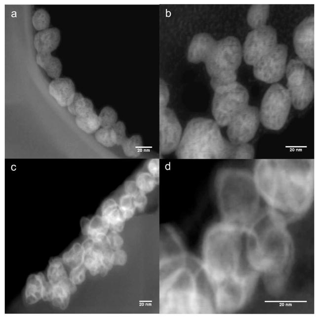
To establish the presence and the spatial distribution of gold, we adopted the Z-contrast approach as two heavy elements that constitute the core (Y) and the shell (Au) are sufficiently far apart in the periodic table to give good contrast and determine the position and distribution of gold. Figure 1 shows the Z-contrast images from scanning transmission electron microscopy (STEM). The gold shell was visible on top of the NP core. Due to the atomic number difference between the yttrium (Z = 39) core and the gold (Z = 79), the gold shell appears as a ‘bright ring’ on top of the core. This was further verified by imaging the uncoated NP in the same mode. These bright features were absent – confirming the formation of gold-coated NPs.
Figure 1.
HAADF-STEM micrographs of uncoated cubic-NaYF4: 20% Yb: 2%Er nanophosphors (a and b). Core-shell architecture of the gold coated nanophosphors is shown in c and d. The gold shell is visible as bright contour in c and d.
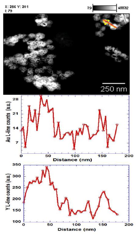
On the other hand, to establish the uniformity of gold coating on different nanoparticles, energy dispersive X-ray spectroscopy (EDS) line scans were employed. Figure 2 shows the EDS collected from different nanoparticles. The profiles of Au and Y revealed a close spatial correlation between signals for the two elements; the EDS results indicate that the Au and Y are not distinct phases but are in fact spatially coincident. From the area under the curve of the EDS, the Au to Y ratio of ~0.07 was obtained from different particles, (see supplementary figure 3), providing a semi-quantitative estimate of the uniformity of gold coating.
Figure 2.
HAADF-STEM images and the EDS line spectra of Au and Y L-lines from gold coated cubic-NaYF4 nanophoshors. Line in the STEM image indicates a transect across three particles, with corresponding profiles of Au and Y concentration shown below. The profile of Au and Y L-line from the particles show a close correspondence that indicates the association of Au with the Y based phosphor.
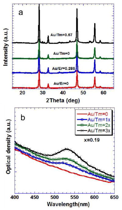
The presence of the Au shell was not detected in X-ray diffraction measurements; it appears that the Au shell is highly disordered. Heating of the core-shell UCNPs to 350 °C did not result in the crystallization of the Au shell (supplementary figure 4). The NaYF4:Yb:Er/Tm phosphor was cubic phase when synthesized and dried at 90 °C (figure 3a). The coated and the uncoated UCNPs were heated to 350 °C in a tubular furnace under a controlled nitrogen atmosphere. To maintain the same heat treatment, all samples were heated in a batch, thus subjecting both to the same conditions. A distinct shell of 4–8 nm was also detected in the BF-TEM micrograph of the calcined gold-coated UCNP (supplementary figure 4). The X-ray diffraction of the heated samples showed that the phase of the UCNP was a mixture of c–NaYF4 and h-NaYF4 phases, with h-NaYF4 being the dominant phase following heat treatment (see supplementary figure 4).
Figure 3.
a) X-ray diffraction from the gold coated and the uncoated (Au/Tm and Au/Er =0) cubic-NaYF4 (JCPDS-77-2042) nanophosphors containing Er3+ and Tm3+heated to 90 °C for 12h. b) Optical absorbance of coated and the uncoated nanophosphors prepared with 0.1% solutions. The Au/Tm(Er) ratio is the molar ratio of Au3+ and Tm3+(Er3+) in the reaction mixture.
The absorbance and emission experiments were performed with 0.1% solution of the colloids prepared using UCNPs dried at 90 °C for 12 h. The colloids were characterized by dynamic light scattering experiments in order to assess the state of aggregation. The colloidal suspension had a particle size distribution corresponding to the primary particle size of the UCNPs (Supplementary figure 5), indicating minimal aggregation. Figure 3b shows the absorbance measured from the gold coated, Tm-containing, c-NaYF4 UCNPs with a maximum at around 525 nm. The absorbance increased with the concentration of HAuCl4 in the solution up to Au/Tm ratio of 0.57 that yielded an easily distinguishable shell thickness of 4–8 nm. The uncoated UCNPs did not show any maximum in absorbance, although a strong inverse wavelength dependence of the measured optical extinction was indicative of the importance of scattering versus absorption. The observations were similar for Er-containing UCNPs (supplementary figure 6a). Although the gold coating is amorphous under X-rays, we expect crystallites of gold of the order of 1–2 nm to be contributing to the plasmonic peaks observed in the absorption spectroscopy.44
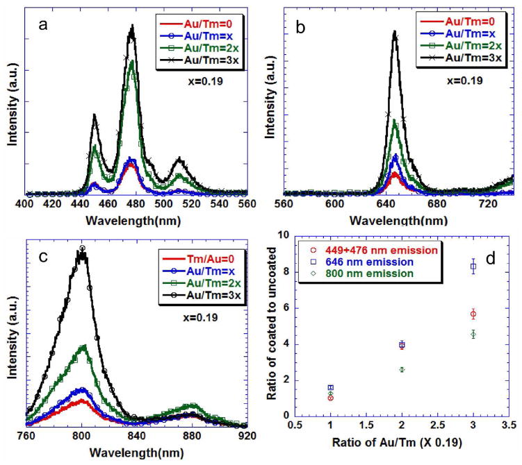
Figure 4 shows the emission characteristics of gold-coated and uncoated Tm-containing c-NaYF4 UCNPs. With increasing concentration of HAuCl4 in the reaction mixture, the blue (1D2–3F4 and 1G4–3H6), green (1D2–3H5), red (1G4–3F4) and the near-infrared (3H4–3H6) emission intensities showed a systematic increase with up to a factor of 8 enhancement, with no quenching effect attributable to the presence of nanoshells on top of the UCNPs.37 The invariant peak at 880 nm in figure 4c was a minor emission from the laser diode that was used for excitation – this peak is not associated with the phosphor emission. The two samples that were tested showed a difference of less than 5%, which was the uncertainty in the power output of the laser. Hence the error was represented as the percentage of the value. This result was in contrast to the effect of the gold shell on h-NaYF4 where the authors observed that a shell around the phosphor quenched the Tm3+ emission.37 This effect could be due to either the higher symmetry of the core or disorder of the shell itself. Nevertheless, it provides an alternative method to enhance up-conversion emission from phosphors in high crystal symmetry hosts.
Figure 4.
Up-converted emission from particles prepared with 0.1% solutions with different gold coatings on cubic -NaYF4: 20%Yb: 1%Tm (a, b and c). d) Integrated area of the emission spectra from gold coated normalized to the uncoated nanophosphor. All solutions were excited at 975 nm.
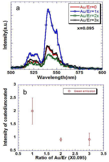
With Er-doped UCNPs, it appeared that the plasmonic enhancement was limited to low concentrations of HAuCl4 and hence lower concentration of Au on the surface of the UCNP. In Er-containing UCNPs (Figure 5), with Au/Er ratio of 0.095, there was a two-fold increase in the emission of green (2H11/2–4I15/2 and 2S3/2–4I15/2) and red emission (4F9/2–4I15/2) and suppression of the near-infrared emission (2S3/2–4I13/2) (supplementary Figure 6), while for higher concentrations of the gold the intensities of emissions are comparable. This could be due to the competing effect of the plasmonic fields and inner-filter effect of the plasmonic shell that has an absorbance peak around 530 nm. It should be noted that plasmonic enhancement of up-conversion in an Er3+ -containing h-NaYF4 phosphor has also been achieved by carefully arranging NPs and plasmonic nanoparticles using atomic force microscopy,45 and by sputtering gold that is more involved than we report here.
Figure 5.
a) Up-converted emission from particles prepared with 0.1% solutions with different gold coatings on cubic -NaYF4: 20%Yb: 2%Er. b) Integrated area of the emission spectra from the gold coated normalized to the uncoated nanophosphors. The error bars are standard deviations from three different samples. The excitation was at 975 nm.
Up-conversion enhancement can arise from two mechanisms: 1) a decrease in the rates of non-radiative decay of the emitting electron or 2) plasmonic electric fields influencing the local electric field (dipole moment), and thereby changing the crystal field around the sensitizer and activator ions. It is well known that the local non-radiative decay and the local crystal structure of the matrix influences the emission from the NaLnF4 matrix. A lower cation radius of the Ln or a lower symmetry of the matrix increases the emission from about a factor of two to an order of magnitude.1 It should be possible to distinguish the former from the latter by comparing two different activator ions with similar chemical and crystal structure. Comparing the effect of the Tm- and-Er containing activators with the same amount of Yb sensitizer in c-NaYF4, it was apparent that the plasmonic electric field was directly affecting the electronic states of the activator ions, as the enhancement in Tm is observed for all three emissions in the visible and the near-infrared regions – the same effect was found lacking in the case of Er activator. The energy levels corresponding to the emission/absorbance states of Tm and Er are slightly different. It should be noted that the two sets of emissions 1G4–3H6, 1G4–3F4 and 2S3/2–4I15/2, 2S3/2–4I13/2 for Tm and Er, respectively, have the same initial state in their respective ions, but the gold shell had quite different impacts on the two emissions. In Tm-containing UCNPs, the plasmonic effect was positive with the enhancement of both emissions, while for Er the higher energy transition, 2S3/2–4I15/2, was enhanced and the 2S3/2–4I13/2 was suppressed, highlighting the subtleties of the plasmonic field effects on energies of emissions. This interplay between emission and plasmonic shell suggests the likelihood of direct coupling of the plasmon electric fields with the local electric fields of the electron state. In addition, emission time constants for the coated and the uncoated phosphor remained the same (not shown), further suggesting that local crystal field changes are the cause of enhancement in these UCNPs.
In addition, a non-radiative decay mechanism can be compared for coated and the uncoated phosphors to see if this was the dominant electron decay mechanism in the presence of gold. The 4F9/2 level is non-radiatively populated from the 4F9/2 level. A comparison of the green and the red emissions should lead to an understanding of the influence that the gold has on the non-radiative decay of the up-converted electron. From Fig. 5a and Supplementary Fig. 6b, the green and the red emissions from the coated and the un-coated sample are comparable, indicating that there was no change in the non-radiative decay in the presence of gold. This in turn indicates that the plasmonic field locally modifies the crystal field around the lanthanide, causing the enhancement in the up-conversion observed in c-NaYF4. The similarity in the green and red emission from the coated and un-coated UCNPs also rules out the possibility that the enhancement was basically due to the removal of citric acid on the surface as the gold is coated. The citric acid was present on the surface of the phosphors in both cases.
The results presented here shows an alternative approach to increasing the emission efficiency from a NaYF4 matrix of high crystal symmetry cubic structure, and a simple route to achieving a factor of 2–8 enhancement depending on the emission energies and the activator. This may be very attractive for biological applications as these core-shell UCNPs are synthesized in aqueous medium and have a visible pink/red color for easy identification in a simple dip-stick or lateral flow bioassay. In addition, given that the Tm emission is enhanced not only in the visible but in the near-infrared region, where common silicon based semiconductor photodetectors are most sensitive, it can be proposed that sensitive, affordable and portable devices for applications such as analyte detection and DNA hybridization can be built employing the properties of the core-shell UCNPs shown here.
4. Conclusions
A simple aqueous technique was employed to produce a new photonic material with plasmonic and up-converting properties by coating gold onto the surface of a fluoride matrix that hosts an up-converting phosphor. The addition of the gold shell enhanced the up-converted emission of the phosphor nanoparticles significantly. Given that the gold also adds visible color to the up-converting NP, effectively providing an additional dimension of optical encoding, we envision many applications, including biomarkers, new arrays of anti-counterfeiting materials and thermal dosimetry in hyperthermia treatment of cancer.
Supplementary Material
Acknowledgments
This work was supported by the United States Department of Agriculture (USDA) Award number 2009-35603-05070 and by Department of Energy- basic energy science (DOE-BES) award number DE-FG02-03ER46057. This publication was also made possible by grant number 5 P42 ES004699 from the National Institute of Environmental Health Sciences (NIEHS), NIH and the contents are solely the responsibility of the authors and do not necessarily represent the official views of the NIEHS, NIH. Authors thank Prof. Bruce Hammock for absorbance measurements and Prof. Thomas Young for dynamic light scattering measurements.
Footnotes
Supporting Information Available: Experimental details, Additional X-ray diffraction, TEM and optical measurements.
References
- 1.Mader HS, Kele P, Saleh SM, Wolfbeis OS. Curr Opin Chem Biol. 2010;14:582. doi: 10.1016/j.cbpa.2010.08.014. [DOI] [PubMed] [Google Scholar]
- 2.Hoppe HA. Angew Chem Int Ed Engl. 2009;48:3572. doi: 10.1002/anie.200804005. [DOI] [PubMed] [Google Scholar]
- 3.Wang F, Liu XG. Chem Soc Rev. 2009;38:976. doi: 10.1039/b809132n. [DOI] [PubMed] [Google Scholar]
- 4.Corstjens P, Zuiderwijk M, Brink A, Li S, Feindt H, Niedbala RS, Tanke H. Clin Chem. 2001;47:1885. [PubMed] [Google Scholar]
- 5.van de Rijke F, Zijlmans H, Li S, Vail T, Raap AK, Niedbala RS, Tanke HJ. Nat Biotechnol. 2001;19:273. doi: 10.1038/85734. [DOI] [PubMed] [Google Scholar]
- 6.Wu SW, Han G, Milliron DJ, Aloni S, Altoe V, Talapin DV, Cohen BE, Schuck PJ. P Natl Acad Sci USA. 2009;106:10917. doi: 10.1073/pnas.0904792106. [DOI] [PMC free article] [PubMed] [Google Scholar]
- 7.Yi GS, Lu HC, Zhao SY, Yue G, Yang WJ, Chen DP, Guo LH. Nano Lett. 2004;4:2191. [Google Scholar]
- 8.Boyer JC, Cuccia LA, Capobianco JA. Nano Lett. 2007;7:847. doi: 10.1021/nl070235+. [DOI] [PubMed] [Google Scholar]
- 9.Chen ZG, Chen HL, Hu H, Yu MX, Li FY, Zhang Q, Zhou ZG, Yi T, Huang CH. J Am Chem Soc. 2008;130:3023. doi: 10.1021/ja076151k. [DOI] [PubMed] [Google Scholar]
- 10.Mai HX, Zhang YW, Si R, Yan ZG, Sun LD, You LP, Yan CH. J Am Chem Soc. 2006;128:6426. doi: 10.1021/ja060212h. [DOI] [PubMed] [Google Scholar]
- 11.Schafer H, Ptacek P, Zerzouf O, Haase M. Adv Funct Mater. 2008;18:2913. [Google Scholar]
- 12.Yi GS, Chow GM. Adv Funct Mater. 2006;16:2324. [Google Scholar]
- 13.Yi GS, Chow GM. Chem Mater. 2007;19:341. [Google Scholar]
- 14.Mahalingam V, Vetrone F, Naccache R, Speghini A, Capobianco JA. Adv Mater. 2009;21:4025. [Google Scholar]
- 15.Vetrone F, Naccache R, Mahalingam V, Morgan CG, Capobianco JA. Adv Funct Mater. 2009;19:2924. [Google Scholar]
- 16.Aslan K, Lakowicz JR, Geddes CD. Curr Opin Chem Biol. 2005;9:538. doi: 10.1016/j.cbpa.2005.08.021. [DOI] [PMC free article] [PubMed] [Google Scholar]
- 17.Daniel MC, Astruc D. Chem Rev. 2004;104:293. doi: 10.1021/cr030698+. [DOI] [PubMed] [Google Scholar]
- 18.Murphy CJ, Gole AM, Stone JW, Sisco PN, Alkilany AM, Goldsmith EC, Baxter SC. Accounts Chem Res. 2008;41:1721. doi: 10.1021/ar800035u. [DOI] [PubMed] [Google Scholar]
- 19.Nam JM, Thaxton CS, Mirkin CA. Science. 2003;301:1884. doi: 10.1126/science.1088755. [DOI] [PubMed] [Google Scholar]
- 20.Wilson R. Chem Soc Rev. 2008;37:2028. doi: 10.1039/b712179m. [DOI] [PubMed] [Google Scholar]
- 21.Lakowicz JR. Anal Biochem. 2005;337:171. doi: 10.1016/j.ab.2004.11.026. [DOI] [PMC free article] [PubMed] [Google Scholar]
- 22.Fu Y, Lakowicz JR. Laser Photonics Rev. 2009;3:221. doi: 10.1002/lpor.200810035. [DOI] [PMC free article] [PubMed] [Google Scholar]
- 23.Tam F, Goodrich GP, Johnson BR, Halas NJ. Nano Lett. 2007;7:496. doi: 10.1021/nl062901x. [DOI] [PubMed] [Google Scholar]
- 24.Alivisatos AP, Gu WW, Larabell C. Annu Rev Biomed Eng. 2005;7:55. doi: 10.1146/annurev.bioeng.7.060804.100432. [DOI] [PubMed] [Google Scholar]
- 25.Kulakovich O, Strekal N, Yaroshevich A, Maskevich S, Gaponenko S, Nabiev I, Woggon U, Artemyev M. Nano Lett. 2002;2:1449. [Google Scholar]
- 26.Song JH, Atay T, Shi SF, Urabe H, Nurmikko AV. Nano Lett. 2005;5:1557. doi: 10.1021/nl050813r. [DOI] [PubMed] [Google Scholar]
- 27.Zin MT, Leong K, Wong NY, Ma H, Sarikaya M, Jen AKY. Nanotechnology. 2009:20. doi: 10.1088/0957-4484/20/1/015305. [DOI] [PubMed] [Google Scholar]
- 28.Lu HC, Yi GS, Zhao SY, Chen DP, Guo LH, Cheng J. J Mater Chem. 2004;14:1336. [Google Scholar]
- 29.Ma ZY, Dosev D, Nichkova M, Gee SJ, Hammock BD, Kennedy IM. J Mater Chem. 2009;19:4695. doi: 10.1039/b901427f. [DOI] [PMC free article] [PubMed] [Google Scholar]
- 30.Wang DS, He JB, Rosenzweig N, Rosenzweig Z. Nano Lett. 2004;4:409. [Google Scholar]
- 31.Xu Z, Hou Y, Sun S. J Am Chem Soc. 2007;129:8698. doi: 10.1021/ja073057v. [DOI] [PubMed] [Google Scholar]
- 32.Ow H, Larson DR, Srivastava M, Baird BA, Webb WW, Wiesner U. Nano Lett. 2005;5:113. doi: 10.1021/nl0482478. [DOI] [PubMed] [Google Scholar]
- 33.Aslan K, Wu M, Lakowicz JR, Geddes CD. J Am Chem Soc. 2007;129:1524. doi: 10.1021/ja0680820. [DOI] [PMC free article] [PubMed] [Google Scholar]
- 34.Tovmachenko OG, Graf C, van den Heuvel DJ, van Blaaderen A, Gerritsen HC. Adv Mater. 2006;18:91. [Google Scholar]
- 35.Ma ZY, Dosev D, Kennedy IM. Nanotechnology. 2009:20. doi: 10.1088/0957-4484/20/8/085608. [DOI] [PMC free article] [PubMed] [Google Scholar]
- 36.Heer S, Kompe K, Gudel HU, Haase M. Adv Mater. 2004;16:2102. [Google Scholar]
- 37.Zhang H, Li Y, Ivanov IA, Qu Y, Huang Y, Duan X. Angew Chem Int Ed Engl. 2010;49:2865. doi: 10.1002/anie.200905805. [DOI] [PMC free article] [PubMed] [Google Scholar]
- 38.Sivakumar S, Diamente PR, van Veggel FC. Chem-Eur J. 2006;12:5878. doi: 10.1002/chem.200600224. [DOI] [PubMed] [Google Scholar]
- 39.Sudarsan V, Sivakumar S, van Veggel FCJM, Raudsepp M. Chem Mater. 2005;17:4736. [Google Scholar]
- 40.Turkevich J, Stevenson PC, Hillier J. Discuss Faraday Soc. 1951:55. [Google Scholar]
- 41.Brown KR, Walter DG, Natan MJ. Chem Mater. 2000;12:306. [Google Scholar]
- 42.Sudheendra L, Han J-H, Kennedy IM. Proc Of SPIE. 2010;7576:75760Y-3. [Google Scholar]
- 43.Pennycook SJ, Varela M, Hetherington CJD, Kirkland AI. Mrs Bull. 2006;31:36. [Google Scholar]
- 44.Salkar RA, Jeevanandam P, Aruna ST, Koltypin Y, Gedanken A. J Mater Chem. 1999;9:1333. [Google Scholar]
- 45.Schietinger S, Aichele T, Wang HQ, Nann T, Benson O. Nano Lett. 2010;10:134. doi: 10.1021/nl903046r. [DOI] [PubMed] [Google Scholar]
- 46.Zhang H, Xu D, Huang Y, Duan X. Chem Commun. 2011;47:979. doi: 10.1039/c0cc03566a. [DOI] [PMC free article] [PubMed] [Google Scholar]
Associated Data
This section collects any data citations, data availability statements, or supplementary materials included in this article.


