Abstract
Though changes in normal joint motions and loads (e.g., following anterior cruciate ligament injury) contribute to the development of knee osteoarthritis, the precise mechanism by which these changes induce osteoarthritis remains unknown. As a first step toward identifying this mechanism, this study evaluates computational wear simulations of a patellofemoral joint specimen wear tested on a knee simulator machine. A multi-body dynamic model of the specimen mounted in the simulator machine was constructed in commercial computer-aided engineering software. A custom elastic foundation contact model was used to calculate contact pressures and wear on the femoral and patellar articular surfaces using geometry created from laser scan and MR data. Two different wear simulation approaches were investigated – one that wore the surface geometries gradually over a sequence of 10 one-cycle dynamic simulations (termed the “progressive” approach), and one that wore the surface geometries abruptly using results from a single one-cycle dynamic simulation (termed the “non-progressive” approach). The progressive approach with laser scan geometry reproduced the experimentally measured wear depths and areas for both the femur and patella. The less costly non-progressive approach predicted deeper wear depths, especially on the patella, but had little influence on predicted wear areas. Use of MR data for creating the articular and subchondral bone geometry altered wear depth and area predictions by at most 13%. These results suggest that MR-derived geometry may be sufficient for simulating articular cartilage wear in vivo and that a progressive simulation approach may be needed for the patella and tibia since both remain in continuous contact with the femur.
Keywords: Computational modeling, Wear simulation, Articular cartilage, Contact analysis, Biomechanics
1. Introduction
According to recent data from the US Centers for Disease Control and Prevention, arthritis costs the US economy close to $128 billion annually and remains the leading cause of disability (CDC, 2007). The most common form, osteoarthritis (OA), disables about 10% of the population above age 60, with the knee being the joint most commonly affected (Buckwalter et al., 2004).
Despite the growing burden of knee OA to society, researchers have made little progress at developing treatments that modify the course of the disease. One reason is the difficulty of performing experimental knee OA studies in human subjects. Consequently, much of the experimental OA research has involved animal or in vitro studies (Setton et al., 1999; Herzog et al., 2004; Griffin and Guilak, 2005). Coupled with clinical observations, such studies have led to viable hypotheses for how biomechanical factors affect the initiation and progression of the disease. One hypothesis proposed by several researchers is that altered joint kinematics (e.g., due to anterior cruciate ligament injury) cause previously unloaded regions of the joint to become overloaded, creating damage that eventually spreads to neighboring regions as well (Wu et al., 2000; Carter et al., 2004; Andriacchi and Mundermann, 2006).
Since contact stresses and strains across the knee’s articular cartilage surfaces cannot be measured accurately in vivo (Winby et al., 2009), a computational approach could be valuable for evaluating such hypotheses and ultimately predicting the outcome of proposed treatment scenarios. Numerous finite element (Li et al., 1999; Donahue et al., 2002; Pena et al., 2006; Papaioannou et al., 2008; Yao et al., 2008b; Yang et al., 2010) and elastic foundation (Blankevoort et al., 1991; Cohen et al., 2003; Bei and Fregly, 2004; Caruntu and Hefzy, 2004; Elias et al., 2004) models of natural knees have been published that are capable of analyzing contact areas, stresses, strains, and/or forces. These models typically use cartilage/bone geometries derived from MR data, with relative bone poses measured using bi-plane fluoroscopy (Papaioannou et al., 2008; Van de Velde et al., 2009a; Van de Velde et al., 2009b; Liu et al., 2010) or MR imaging (Salsich et al., 2003; Gold et al., 2004; Yao et al., 2008a; Connolly et al., 2009). Despite this breadth of models, to the best of the authors' knowledge, only two studies have predicted articular cartilage wear in the knee computationally, both under approximated in vivo conditions (Andriacchi et al., 2006; Pena et al., 2008). No study has compared articular cartilage wear predictions with cartilage wear measured in the same knee, either under in vivo or in vitro conditions as performed for artificial knees (Fregly et al., 2005; Knight et al., 2007; Zhao et al., 2008; Willing and Kim, 2009; Strickland et al., 2010).
This study evaluated the ability of a cadaver-specific computational model of the patellofemoral joint to reproduce articular cartilage wear depths and areas measured from the same specimen following testing in a knee simulator machine. Computational simulation of an in vitro situation with no menisci and well-controlled motion and loads inputs provides a valuable first step toward computational simulation of the more complex in vivo situation. The three specific goals of the study were as follows: 1) To evaluate whether the model can reproduce experimentally measured wear depths and areas for both the femur and patella, 2) To assess whether a progressive simulation approach that wears the articular surface geometry gradually over a sequence of simulations significantly alters the wear predictions, and 3) To determine whether the source of imaging data (i.e., laser scan or MR) used to construct articular surface geometry significantly affects the predicted wear.
2. Methods
2.1 Experimental Wear Testing
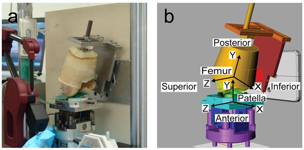
A single cadaveric patellofemoral joint specimen was wear tested in a multi-axial knee simulator machine (Force 5, AMTI, Watertown, MA). The specimen exhibited no visible signs of articular cartilage degeneration in the anticipated regions of contact. The femur was cut approximately 10 cm above the joint line, and titanium beads were embedded around the edges of the patella and distal femur for subsequent surface model registration purposes. The specimen and titanium beads were laser and MR scanned prior to wear testing and laser scanned again after wear testing. The patella and femur were mounted in the Force 5 knee simulator machine with the patellar articulating surface facing upward (Fig. 1a). Prior to wear testing, the specimen was contact pressure tested to estimate an effective Young’s modulus for the subsequent computational wear simulations (Fig 2a). Details of specimen scanning and subsequent surface model creation, specimen mounting, and specimen contact pressure testing are included as Supplementary Material.
Figure 1.
(a) Cadaveric patellofemoral joint specimen mounted in an AMTI Force 5 knee simulator machine for Tekscan contact pressure testing and subsequent wear testing. (b) Geometric model of the same specimen mounted in an identical manner in a multibody dynamic model of the simulator machine. Deformable contact between the femoral and patellar articular cartilage was modeled using an elastic foundation model. Bone-fixed coordinate systems are as indicated in the figure.
Figure 2.
Contact pressures and areas (a) measured by a Tekscan K-scan sensor and (b) predicted by the elastic foundation contact model when the model of the simulator machine was placed in the same configuration as the actual machine during pressure testing.
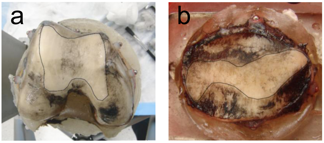
Following contact pressure testing, the specimen was wear tested for 375,000 motion cycles of simulated gait (approximately 2 months in vivo, (Schmalzried et al., 2000)). The applied flexion angle and axial load profiles were taken from the literature (Ward and Powers, 2004). The patella was mounted in a new fixture that allowed the entire specimen to remain bathed in a solution of phosphate buffered saline with proteinase inhibitors (Frank et al., 1987). This solution was used to minimize cartilage enzymatic degradation so that experimental cartilage damage, as visualized using India ink (Fig. 3) and measured using the aligned pre- and post-test laser scan geometry, would be due primarily to mechanical wear.
Figure 3.
Experimental wear areas at the end of wear testing on the (a) femur and (b) patella as identified by removal of India ink. White outlined areas are worn regions.
2.2 Computational Wear Simulation
A computational model of the cadaver knee specimen mounted in the simulator machine was constructed using Pro/MECHANICA MOTION (PTC, Waltham, MA) (Fig. 1b). The degrees of freedom in the multibody dynamic model matched those of the simulator machine. Geometric models of the machine components and aluminum fixtures were created in CAD software based on the measured dimensions of each component. Digitized titanium bead locations were used to align the femur and patella cartilage/bone geometries with the geometric models of their respective fixtures. The laser scan geometry was the more accurate representation of the articular cartilage and subchondral bone geometry and was therefore used as the starting point for all wear simulations.
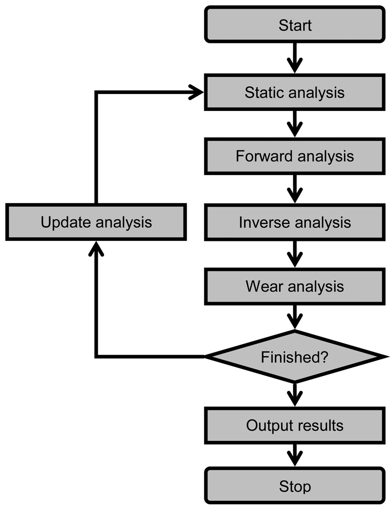
A previously published computational methodology was used to simulate progressive cartilage wear on both articular surfaces over multiple loading cycles (Fig. 4) (Knight et al., 2007; Zhao et al., 2008). The methodology employs a modified version of an elastic foundation model (Bei and Fregly, 2004) to simulate deformable contact between the patellar and femoral articular surfaces. Both bones were treated as layered elastic bodies with non-uniform thickness, where the thickness at any articular surface location was defined as the distance to the closest point on the subchondral bone. A uniform grid of contact elements was placed on the patella, and the contact pressure p on each element was calculated using the modified elastic foundation equation (Zhao et al., 2008)
| (1) |
where v is Poisson’s ratio of the articular cartilage, E is effective Young’s modulus of the cartilage, h = hfem + hpat is the combined thickness of the femoral and patellar cartilage layers, d is the interpenetration of the undeformed and unworn articular surfaces, and δ = δfem + δpat is the combined accumulated wear depth of the femoral and patellar cartilage layers, with h, d, and δ being measured at the center of the element. The modification in Eq. (1) is inclusion of δ in the numerator and denominator to account for cartilage removed due to wear. A uniform grid of contact elements was also placed on the femur, and each patellar contact element stored hpat and δpat values while each femoral contact element stored hfem and δfem values. Since element centers on opposing surfaces are not normally aligned, Eq. (1) was solved using interpolated values of hfem and δfem from the femoral elements closest to the patellar element being analyzed. Femoral contact pressures were calculated by repeating the entire process for the contact elements on the femur.
Figure 4.
Overview of the computational steps involved in performing a progressive wear simulation of articular cartilage. First, a static analysis determines the initial configuration of the contacting bones. Second, a forward dynamic simulation predicts bone motions and loads over one loading cycle. Third, an inverse dynamic analysis calculates contact pressures and sliding conditions on the patellar and femoral contact elements. Fourth, a wear analysis calculates the incremental change in wear depth for each element. Fifth, an update analysis calculates the new accumulated wear depth for each contact element, and the entire process is repeated.
The accumulated depth of cartilage removed δs (s = pat or fem) from each contact element on both surfaces was calculated using an iterative version of Archard’s classic law for mild wear (Archard, 1956; Knight et al., 2007; Zhao et al., 2008):
| (2) |
where
| (3) |
with the initial unworn condition δs(0) = 0. In Eq. (2), j represents the loading cycle number, δs (j) is the element’s accumulated wear depth up through the jth cycle, and N is the number of loading cycles for which an incremental wear depth change Δδs (j + 1) is to be extrapolated. Calculation of Δδs (j + 1) via Eq. (3) requires results from a one-cycle dynamic simulation for loading cycle j+1, where k is a constant wear factor, i is a time frame within a one-cycle dynamic simulation with n time frames, pi is the element’s contact pressure, |vi| is the magnitude of the element’s relative sliding velocity, and Δti is the time increment used in the dynamic simulation so that |vi|Δti is the sliding distance experienced by the element. Wear simulations that predicted final wear depths and areas using a single one-cycle dynamic simulation (i.e., N = 375,000 with n = 101) were termed “non-progressive” since progressive changes in articular surface geometry were not simulated. Similarly, wear simulations that predicted final wear depths and areas using a sequence of 10 one-cycle dynamic simulations (i.e., N = 37,500 with n = 101) (Zhao et al., 2008) were termed “progressive” since the articular geometry of both surfaces was changed progressively.
The effective Young’s modulus E and material wear factor k used in the wear simulations were calibrated to experimental data and remained constant throughout the simulation process. To calibrate E, we adjusted the degrees of freedom in the simulator machine model such that the titanium bead locations in the model closely matched their experimentally measured locations during contact pressure testing (Fig 1b). The value of E (1.5 MPa) was found that allowed a static analysis performed with the model to match the contact force and area measurements on each side as closely as possible (Fib. 2b, Table 1).
Table 1.
Comparison between measured (mean ± standard deviation from three trials) and predicted contact force and area on the medial and lateral sides of the patellofemoral joint specimen during static contact pressure testing.
| Medial Side |
Lateral Side |
|||
|---|---|---|---|---|
| Contact Force (N) | Contact Area (mm2) | Contact Force (N) | Contact Area (mm2) | |
| Measured | 182.0 ± 2.2 | 155.4 ± 2.5 | 241.0 ± 1.8 | 279.8 ± 9.4 |
| Predicted | 182.7 | 159.1 | 240.3 | 268.4 |
To calibrate k, we performed four progressive wear simulations to seek the k value that best matched the experimental wear depths for the femur and patella. Progressive rather non-progressive simulations were performed since the progressive approach was expected to produce the most accurate wear predictions (Knight et al., 2007; Zhao et al., 2008). Three progressive simulations used k values that predicted wear depths that were too shallow, too deep, and somewhere in between. Quadratic interpolation was then used to estimate the k value that would best match the experimental measurements. A fourth progressive simulation was performed to verify that the selected k value (2.5 × 10⁻⁵ mm3/Nm) provided a good fit to the experimental data. Since the patella was remounted in a new fixture following static pressure testing, minor adjustments were made to the position and orientation of the patella in the model so that the simulated wear regions remained consistent with those observed experimentally.
Starting from this nominal model configuration, sensitivity analyses were performed to assess the influence of simulation approach (non-progressive versus progressive), geometry source (laser scan versus MR), bone alignment (small variations in femoral and patellar position and orientation with respect to their fixtures), machine set up (small variations in input motion profiles and load line of action), and material properties (variations in effective Young’s modulus) on the wear predictions. The goal of the sensitivity analyses was to identify methodological and measurement issues that could affect future in vivo and in vitro computational simulations of articular cartilage wear in both the patellofemoral and tibiofemoral joints. Due to the significantly longer computation time for progressive wear simulations, all sensitivity analyses apart from the first two were performed using a non-progressive simulation approach. Sensitivity analyses involving changes in a position or orientation parameter used a range of ± 1 mm or ± 1 deg, respectively, comparable to the estimated accuracy of bone positioning within the machine as well as of bone poses measured in vivo using single plane fluoroscopy with MR-derived bone models (Moro-oka et al., 2007). Sensitivity analysis involving effective Young’s modulus used a range of ± 0.5 MPa.
3. Results
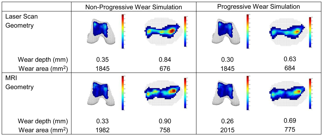
Wear predictions exhibited significant sensitivity to choice of simulation approach (non-progressive versus progressive) but only mild sensitivity to source of cartilage geometry (laser scan versus MR) (Fig. 5). The “gold standard” progressive simulation using laser scan geometry was able to match the experimentally measured femoral and patellar maximum wear depths simultaneously to within 0.01 mm, with the predicted wear regions and locations of maximum wear depth closely matching those observed experimentally (see Fig. 3). Significant sensitivity to simulation approach was observed only for wear depth predictions, especially for the patella. When switching from a progressive to a non-progressive approach, wear depths increased by 17 to 33% while wear areas decreased by only 2%. In contrast, mild sensitivity to geometry source was observed for both wear depth and area predictions. When switching from laser scan to MR geometry, wear depths decreased by 6 to 13% for the femur and increased by 7 to 10% for the patella, while wear areas increased by 7 to 13% for both the femur and patella.
Figure 5.
Sensitivity of wear depth and area predictions to simulation approach (non-progressive versus progressive - columns) and geometry source (laser scan versus MR - rows). The progressive approach with laser scan geometry is taken as the “gold standard” case, while for reasons of computation time, the non-progressive approach with laser scan geometry is taken as the nominal case for subsequent sensitivity analyses. Based on laser scanner accuracy, the experimentally measured maximum wear depths were 0.29 ± 0.13 mm for the femur and 0.63 ± 0.13 mm for the patella.
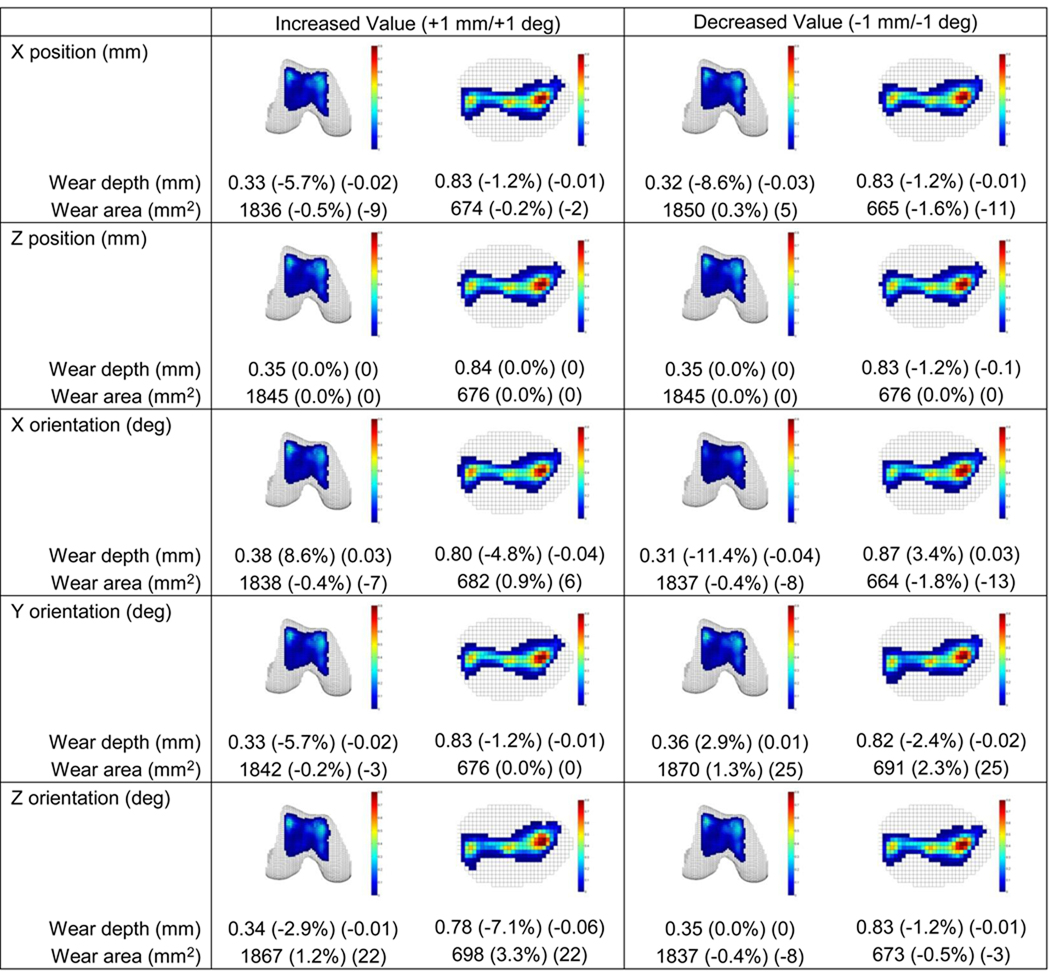
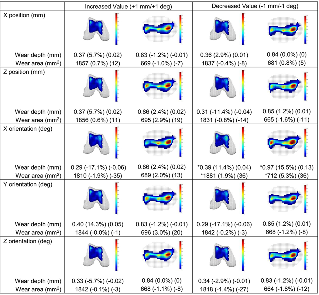
Sensitivity of wear predictions to small patellar and femoral pose variations (Figs. 6 and 7) and small simulator machine set up variations (Fig. S1) was generally low. For all variations, changes in predicted wear areas were low, with the maximum change being 5%. In contrast, changes in predicted wear depths were as large as 17%, with changes greater than 10% occurring for several pose variations. These included patellar internal rotation and femoral lateral translation, internal and external rotation, and varus and valgus rotation. With the exception of femoral internal rotation, these pose variations caused an increase (decrease) in femoral wear depth that corresponded to a decrease (increase) in patellar wear depth. For machine set up variations, only a medial shift in the axial load produced a wear depth change of more than 10%.
Figure 6.
Sensitivity of wear depth and area predictions to patellar pose variations of ± 1 mm or ± 1 deg. Relative and absolute changes indicated in parentheses are with respect to non-progressive results generated using laser scan geometry (see Fig. 5). X is anatomic inferior direction, Y is anatomic posterior direction, and Z is anatomic medial direction (review Fig. 1b). No Y position variations are reported since this direction was free to self-adjust under the influence of the applied load. Only a decreased X orientation change (i.e., patellar internal rotation) resulted in a wear-related change of more than 10%.
Figure 7.
Sensitivity of wear depth and area predictions to femoral pose variations of ± 1 mm or ± 1 deg. Relative and absolute changes indicated in parentheses are with respect to non-progressive results generated using laser scan geometry (see Fig. 5). X, Y, and Z directions are defined as in Fig. 6, and no Y position variations are again reported. Three of the five position and orientation changes produced a wear-related change of more than 10%. For decreased X orientation change (i.e., femoral internal rotation, indicated by stars), only a 0.7 deg change could be performed without the simulation becoming unstable.
Sensitivity of wear predictions to effective Young’s modulus was moderate to large (Fig. S2). Use of a larger value of 2.0 MPa changed predicted wear depths and areas by 4 to 16% for the non-progressive simulation and 0 to 8% for the progressive one with a new calibrated wear factor. Use of a smaller value of 1.0 MPa prevented a one-cycle dynamic simulation from completing, making wear prediction impossible.
4. Discussion
This study evaluated different computational methods for simulating in vitro articular cartilage wear in the patellofemoral joint. The evaluation used a unique combination of experimental, computational, and imaging techniques to provide the first (to our knowledge) published comparison between experimentally measured and computationally simulated cartilage wear patterns for the same knee. The “gold standard” progressive simulation with laser scan geometry successfully reproduced the experimentally measured wear depths and areas for both the femur and patella, indicating that the model provided an accurate representation of the in vitro wear phenomenon. Compared to the progressive approach, the less costly non-progressive approach altered the predicted wear depths significantly, especially for the patella, but had little influence on the predicted wear areas. Use of less accurate MR data for creating the articular and subchondral bone geometry altered wear depth and area predictions by at most 13%. Finally, the largest sensitivity to bone positioning within the simulator machine was for internal-external rotation. When extrapolated to simulation of osteoarthritis development in the patellofemoral and tibiofemoral joints, these findings suggest that MRI-derived geometry may be sufficiently accurate, a progressive simulation method may be necessary for the patella and tibia since both remain in continuous contact with the femur, and accurate loading of the patellofemoral joint in internal-external rotation and the tibiofemoral joint in varus-valgus rotation (the related sensitive rotation (Fregly et al., 2008)) may be critical.
The most obvious limitation of this study was testing nonviable rather than living cartilage tissue. If we were unsuccessful at simulating dead tissue under well-controlled conditions, where it is reasonable to use Archard’s wear law and where the articular surface geometry and final wear depths and areas can be measured directly, we would have little hope of successfully simulating osteoarthritis development in living tissue under more variable conditions. While use of a linearly elastic and frictionless contact model for articular cartilage was yet another potential limitation, this simplification did not degrade the ability of the model to reproduce the experimentally measured wear patterns.
Calibration of the wear factor to the experimental wear depths may initially make the model predictions seem unimpressive. However, since the k value affects the wear depth of both surfaces in a coupled manner, there is no guarantee that a single k value exists that will allow the model to match the maximum wear depths for both surfaces simultaneously. One can only guarantee that the model will match the maximum wear depth for one surface or distribute wear depth errors equally between the two surfaces. Furthermore, the selected value of Young’s modulus limits the effectiveness of wear factor tuning. The ratio maximum patellar to femoral wear depth was 2.17 experimentally. Using the calibrated modulus of 1.5 MPa with the original wear factor, the wear simulation predicted a ratio of 2.10. Using the larger modulus of 2.0 MPa with a recalibrated wear factor, the predicted ratio was 1.97.
Our wear sensitivity results for bone pose variations in the simulator machine are consistent with a recent clinical study of patellofemoral pain. In our study, an internally rotated femur produced the largest wear depths for both the femur and patella. Thus, externally rotating the femur from this pose to the neutral pose would result in significant reductions in wear. In a recent clinical study (Noehren et al., 2010), ten runners with patellofemoral pain syndrome (presumably related to excessive internal hip rotation) were given eight sessions of gait retraining to learn to externally rotate their hips while running. By the end of the study, all subjects were able to run pain-free.
A complicating factor for performing in vivo cartilage wear simulations is the lack of a validated cartilage adaptation law. Such a law is needed to explain how in vivo cartilage material properties and thickness change in response to altered joint motions and loads. Two studies have simulated whole-joint cartilage thickness changes in the knee (Andriacchi and Mundermann, 2006; Pena et al., 2008), and two studies have performed similar simulations for the ankle (Anderson et al., 2006; Li et al., 2008). These studies used octahedral shear stress distribution (Andriacchi and Mundermann, 2006), shear stress increase (Pena et al., 2008), and contact stress (Anderson et al., 2006; Li et al., 2008) as inputs to their proposed cartilage adaptation laws. However, none of these studies compared cartilage wear measured experimentally with that predicted computationally for the same joint. Future in vivo studies are needed that perform such comparisons using different proposed cartilage adaptation laws.
Supplementary Material
Acknowledgments
This material is based upon work supported by the National Science Foundation under grant number 0828253 (B.J.F), the Shiley Center for Orthopaedic Research and Education (D.D.D.), the National Institutes of Health under grant number R01 AR051565 (R.L.S.), and the University of Florida (B.J.F.). The study sponsors had no involvement in the study design, in the collection, analysis and interpretation of data, in the writing of the manuscript, or in the decision to submit the manuscript for publication.
Footnotes
Publisher's Disclaimer: This is a PDF file of an unedited manuscript that has been accepted for publication. As a service to our customers we are providing this early version of the manuscript. The manuscript will undergo copyediting, typesetting, and review of the resulting proof before it is published in its final citable form. Please note that during the production process errors may be discovered which could affect the content, and all legal disclaimers that apply to the journal pertain.
Conflict of Interest Statement
None of the authors have any potential financial or personal conflicts of interest.
References
- Anderson DD, Goldsworthy JK, Shivanna K, Grosland NM, Pedersen DR, Thomas TP, Tochigi Y, Marsh JL, Brown TD. Intra-articular contact stress distributions at the ankle throughout stance phase-patient-specific finite element analysis as a metric of degeneration propensity. Biomech Model Mechanobiol. 2006;5:82–89. doi: 10.1007/s10237-006-0025-2. [DOI] [PMC free article] [PubMed] [Google Scholar]
- Andriacchi TP, Briant PL, Bevill SL, Koo S. Rotational changes at the knee after ACL injury cause cartilage thinning. Clin Orthop Relat Res. 2006;442:39–44. doi: 10.1097/01.blo.0000197079.26600.09. [DOI] [PubMed] [Google Scholar]
- Andriacchi TP, Mundermann A. The role of ambulatory mechanics in the initiation and progression of knee osteoarthritis. Curr Opin Rheumatol. 2006;18:514–518. doi: 10.1097/01.bor.0000240365.16842.4e. [DOI] [PubMed] [Google Scholar]
- Archard JF, Hirst W. The wear of metals under unlubricated conditions. Proceedings of the Royal Society A. 1956;236:397–410. [Google Scholar]
- Bei Y, Fregly BJ. Multibody dynamic simulation of knee contact mechanics. Med Eng Phys. 2004;26:777–789. doi: 10.1016/j.medengphy.2004.07.004. [DOI] [PMC free article] [PubMed] [Google Scholar]
- Blankevoort L, Kuiper JH, Huiskes R, Grootenboer HJ. Articular contact in a three-dimensional model of the knee. J Biomech. 1991;24:1019–1031. doi: 10.1016/0021-9290(91)90019-j. [DOI] [PubMed] [Google Scholar]
- Buckwalter JA, Saltzman C, Brown T. The impact of osteoarthritis: implications for research. Clin Orthop Relat Res. 2004:S6–S15. doi: 10.1097/01.blo.0000143938.30681.9d. [DOI] [PubMed] [Google Scholar]
- Carter DR, Beaupre GS, Wong M, Smith RL, Andriacchi TP, Schurman DJ. The mechanobiology of articular cartilage development and degeneration. Clin Orthop Relat Res. 2004:S69–S77. doi: 10.1097/01.blo.0000144970.05107.7e. [DOI] [PubMed] [Google Scholar]
- Caruntu DI, Hefzy MS. 3-D anatomically based dynamic modeling of the human knee to include tibio-femoral and patello-femoral joints. J Biomech Eng. 2004;126:44–53. doi: 10.1115/1.1644565. [DOI] [PubMed] [Google Scholar]
- CDC. National and state medical expenditures and lost earnings attributable to arthritis and other rheumatic conditions--United States, 2003. MMWR Morb Mortal Wkly Rep. 2007;56:4–7. [PubMed] [Google Scholar]
- Cohen ZA, Henry JH, McCarthy DM, Mow VC, Ateshian GA. Computer simulations of patellofemoral joint surgery. Patient-specific models for tuberosity transfer. Am J Sports Med. 2003;31:87–98. doi: 10.1177/03635465030310012701. [DOI] [PubMed] [Google Scholar]
- Connolly KD, Ronsky JL, Westover LM, Kupper JC, Frayne R. Differences in patellofemoral contact mechanics associated with patellofemoral pain syndrome. J Biomech. 2009 doi: 10.1016/j.jbiomech.2009.07.028. [DOI] [PubMed] [Google Scholar]
- Donahue TL, Hull ML, Rashid MM, Jacobs CR. A finite element model of the human knee joint for the study of tibio-femoral contact. J Biomech Eng. 2002;124:273–280. doi: 10.1115/1.1470171. [DOI] [PubMed] [Google Scholar]
- Elias JJ, Wilson DR, Adamson R, Cosgarea AJ. Evaluation of a computational model used to predict the patellofemoral contact pressure distribution. J Biomech. 2004;37:295–302. doi: 10.1016/s0021-9290(03)00306-3. [DOI] [PubMed] [Google Scholar]
- Frank EH, Grodzinsky AJ, Koob TJ, Eyre DR. Streaming potentials: a sensitive index of enzymatic degradation in articular cartilage. J Orthop Res. 1987;5:497–508. doi: 10.1002/jor.1100050405. [DOI] [PubMed] [Google Scholar]
- Fregly BJ, Banks SA, D'Lima DD, Colwell CW., Jr Sensitivity of knee replacement contact calculations to kinematic measurement errors. J Orthop Res. 2008;26:1173–1179. doi: 10.1002/jor.20548. [DOI] [PubMed] [Google Scholar]
- Fregly BJ, Sawyer WG, Harman MK, Banks SA. Computational wear prediction of total knee replacement from in vivo kinematics. J Biomech. 2005;38:305–314. doi: 10.1016/j.jbiomech.2004.02.013. [DOI] [PubMed] [Google Scholar]
- Gold GE, Besier TF, Draper CE, Asakawa DS, Delp SL, Beaupre GS. Weight-bearing MRI of patellofemoral joint cartilage contact area. Journal of Magnetic Resonance Imaging. 2004;20:526–530. doi: 10.1002/jmri.20146. [DOI] [PubMed] [Google Scholar]
- Griffin TM, Guilak F. The role of mechanical loading in the onset and progression of osteoarthritis. Exerc Sport Sci Rev. 2005;33:195–200. doi: 10.1097/00003677-200510000-00008. [DOI] [PubMed] [Google Scholar]
- Herzog W, Clark A, Longino D. Joint mechanics in osteoarthritis. Novartis Found Symp. 2004;260:79–95. discussion 95-79, 100-104, 277-109. [PubMed] [Google Scholar]
- Knight LA, Pal S, Coleman JC, Bronson F, Haider H, Levine DL, Taylor M, Rullkoetter PJ. Comparison of long-term numerical and experimental total knee replacement wear during simulated gait loading. Journal of Biomechanics. 2007;40:1550–1558. doi: 10.1016/j.jbiomech.2006.07.027. [DOI] [PubMed] [Google Scholar]
- Li G, Gil J, Kanamori A, Woo SL. A validated three-dimensional computational model of a human knee joint. J Biomech Eng. 1999;121:657–662. doi: 10.1115/1.2800871. [DOI] [PubMed] [Google Scholar]
- Li W, Anderson DD, Goldsworthy JK, Marsh JL, Brown TD. Patient-specific finite element analysis of chronic contact stress exposure after intraarticular fracture of the tibial plafond. J Orthop Res. 2008;26:1039–1045. doi: 10.1002/jor.20642. [DOI] [PMC free article] [PubMed] [Google Scholar]
- Liu F, Kozanek M, Hosseini A, Van de Velde SK, Gill TJ, Rubash HE, Li G. In vivo tibiofemoral cartilage deformation during the stance phase of gait. J Biomech. 2010;43:658–665. doi: 10.1016/j.jbiomech.2009.10.028. [DOI] [PMC free article] [PubMed] [Google Scholar]
- Moro-oka TA, Hamai S, Miura H, Shimoto T, Higaki H, Fregly BJ, Iwamoto Y, Banks SA. Can magnetic resonance imaging-derived bone models be used for accurate motion measurement with single-plane three-dimensional shape registration? J Orthop Res. 2007;25:867–872. doi: 10.1002/jor.20355. [DOI] [PubMed] [Google Scholar]
- Noehren B, Scholz J, Davis I. The effect of real-time gait retraining on hip kinematics, pain and function in subjects with patellofemoral pain syndrome. Br J Sports Med. 2010 doi: 10.1136/bjsm.2009.069112. [DOI] [PubMed] [Google Scholar]
- Papaioannou G, Nianios G, Mitrogiannis C, Fyhrie D, Tashman S, Yang KH. Patient-specific knee joint finite element model validation with high-accuracy kinematics from biplane dynamic Roentgen stereogrammetric analysis. J Biomech. 2008;41:2633–2638. doi: 10.1016/j.jbiomech.2008.06.027. [DOI] [PubMed] [Google Scholar]
- Pena E, Calvo B, Martinez MA, Doblare M. A three-dimensional finite element analysis of the combined behavior of ligaments and menisci in the healthy human knee joint. J Biomech. 2006;39:1686–1701. doi: 10.1016/j.jbiomech.2005.04.030. [DOI] [PubMed] [Google Scholar]
- Pena E, Calvo B, Martinez MA, Doblare M. Computer simulation of damage on distal femoral articular cartilage after meniscectomies. Comput Biol Med. 2008;38:69–81. doi: 10.1016/j.compbiomed.2007.07.003. [DOI] [PubMed] [Google Scholar]
- Salsich GB, Ward SR, Terk MR, Powers CM. In vivo assessment of patellofemoral joint contact area in individuals who are pain free. Clin Orthop Relat Res. 2003:277–284. doi: 10.1097/01.blo.0000093024.56370.79. [DOI] [PubMed] [Google Scholar]
- Schmalzried TP, Shepherd EF, Dorey FJ, Jackson WO, dela Rosa M, Fa'vae F, McKellop HA, McClung CD, Martell J, Moreland JR, Amstutz HC. The John Charnley Award. Wear is a function of use, not time. Clin Orthop Relat Res. 2000:36–46. doi: 10.1097/00003086-200012000-00005. [DOI] [PubMed] [Google Scholar]
- Setton LA, Elliott DM, Mow VC. Altered mechanics of cartilage with osteoarthritis: human osteoarthritis and an experimental model of joint degeneration. Osteoarthritis Cartilage. 1999;7:2–14. doi: 10.1053/joca.1998.0170. [DOI] [PubMed] [Google Scholar]
- Strickland MA, Dressler MR, Render T, Browne M, Taylor M. Targeted computational probabilistic corroboration of experimental knee wear simulator: The importance of accounting for variability. Med Eng Phys. 2010 doi: 10.1016/j.medengphy.2010.10.015. [DOI] [PubMed] [Google Scholar]
- Van de Velde SK, Bingham JT, Gill TJ, Li G. Analysis of tibiofemoral cartilage deformation in the posterior cruciate ligament-deficient knee. J Bone Joint Surg Am. 2009a;91:167–175. doi: 10.2106/JBJS.H.00177. [DOI] [PMC free article] [PubMed] [Google Scholar]
- Van de Velde SK, Bingham JT, Hosseini A, Kozanek M, DeFrate LE, Gill TJ, Li G. Increased tibiofemoral cartilage contact deformation in patients with anterior cruciate ligament deficiency. Arthritis Rheum. 2009b;60:3693–3702. doi: 10.1002/art.24965. [DOI] [PMC free article] [PubMed] [Google Scholar]
- Ward SR, Powers CM. The influence of patella alta on patellofemoral joint stress during normal and fast walking. Clinical Biomechanics. 2004;19:1040–1047. doi: 10.1016/j.clinbiomech.2004.07.009. [DOI] [PubMed] [Google Scholar]
- Willing R, Kim IY. A holistic numerical model to predict strain hardening and damage of UHMWPE under multiple total knee replacement kinematics and experimental validation. J Biomech. 2009;42:2520–2527. doi: 10.1016/j.jbiomech.2009.07.008. [DOI] [PubMed] [Google Scholar]
- Winby CR, Lloyd DG, Besier TF, Kirk TB. Muscle and external load contribution to knee joint contact loads during normal gait. Journal of Biomechanics. 2009;42:2294–2300. doi: 10.1016/j.jbiomech.2009.06.019. [DOI] [PubMed] [Google Scholar]
- Wu JZ, Herzog W, Epstein M. Joint contact mechanics in the early stages of osteoarthritis. Med Eng Phys. 2000;22:1–12. doi: 10.1016/s1350-4533(00)00012-6. [DOI] [PubMed] [Google Scholar]
- Yang NH, Nayeb-Hashemi H, Canavan PK, Vaziri A. Effect of frontal plane tibiofemoral angle on the stress and strain at the knee cartilage during the stance phase of gait. J Orthop Res. 2010;28:1539–1547. doi: 10.1002/jor.21174. [DOI] [PubMed] [Google Scholar]
- Yao J, Lancianese SL, Hovinga KR, Lee J, Lerner AL. Magnetic resonance image analysis of meniscal translation and tibio-menisco-femoral contact in deep knee flexion. J Orthop Res. 2008a;26:673–684. doi: 10.1002/jor.20553. [DOI] [PubMed] [Google Scholar]
- Yao J, Salo AD, Lee J, Lerner AL. Sensitivity of tibio-menisco-femoral joint contact behavior to variations in knee kinematics. J Biomech. 2008b;41:390–398. doi: 10.1016/j.jbiomech.2007.08.015. [DOI] [PubMed] [Google Scholar]
- Zhao D, Sakoda H, Sawyer WG, Banks SA, Fregly BJ. Predicting knee replacement damage in a simulator machine using a computational model with a consistent wear factor. J Biomech Eng. 2008;130:011004. doi: 10.1115/1.2838030. [DOI] [PubMed] [Google Scholar]
Associated Data
This section collects any data citations, data availability statements, or supplementary materials included in this article.


