Abstract
Bioluminescence tomography (BLT) is an inverse source problem that localizes and quantifies bioluminescent probe distribution in 3D. The generic BLT model is ill-posed, leading to non-unique solutions and aberrant reconstruction in the presence of measurement noise and optical parameter mismatches. In this paper, we introduce the knowledge of the number of bioluminescence sources to stabilize the BLT problem. Based on this regularized BLT model, we develop a differential evolution-based reconstruction algorithm to determine the source locations and strengths accurately and reliably. Then, we evaluate this novel approach in numerical, phantom, and mouse studies.
Keywords: bioluminescence tomography (BLT), diffusion approximation (DA), inverse source problem, reconstruction algorithm, differential evolution (DE)
I. Introduction
Bioluminescence imaging (BLI) is a molecular imaging modality, which can be used to monitor physiological and pathological activities at the molecular level. Various applications include visualizing tumor growth, tracking tumor cell metastasis, and evaluating drug delivery [1]-[3]. Light-emitting bioluminescent probes, such as firefly, Gaussia, and Renilla luciferasesn enzymes, release photons when they react with substrate, oxygen and ATP [4]. The emission wavelength for the enzyme-substrate reporter is between 460-630 nm, allowing deep tissue penetration. A significant number of bioluminescence photons can escape the attenuating environment in small animals and be detected by a highly sensitive charge-coupled device (CCD) camera [4], [5]. However, BLI is primarily qualitative as it cannot resolve depth and quantify features.
Bioluminescence tomography (BLT) uses multiple BLI acquisitions, geometrical structures, and tissue optical properties to reconstruct the bioluminescent source distribution [6] based on a photon propagation model. The radiative transfer equation (RTE) is considered as the most accurate model for the light transport in tissue [7]-[9]. However, the high computational cost of RTE makes it inappropriate for bioluminescence tomography. Various approximations of RTE, such as discrete ordinates [10], [11], spherical harmonics [12] and the diffusion approximation (DA) [13] are used in practice. The DA, due to its high computational efficiency and sufficient accuracy in highly scattering media, is the most popular photon propagation model for BLT. Using the finite element analysis, a linear model between the bioluminescent source distribution and photon fluence rate is established [14], [15], converting the inverse source problem into an optimization task.
This tomographic imaging modality faces several challenges to its accuracy and stability. The generic BLT problem is ill-posed, meaning it is sensitive to noise and bears multiple solutions. Researchers have invested considerable effort to obtain stable solutions for BLT. Tikhonov regularization is often used to alleviate the ill-posed nature of this problem [16]-[18]. Cong et al. used the permissible bioluminescent source region to stabilize reconstruction results [15]. Recently, reconstructions using multi-spectral measurements [16]-[18] and varying boundary conditions [19] have been proposed to enhance the stability of the solution. Although these techniques improve the reconstruction stability, none of them warrants an unique solution of the BLT problem.
In this manuscript, we used a predetermined number of isolated sources to regularize the BLT problem such that an unique solution could be obtained. The differential evolution (DE) algorithm is applied to solve this problem by integrating the number of bioluminescent sources as constraint in its encoding scheme and locating the global optimum solution using a metaheuristic approach. Furthermore, we implemented an iterative method to estimate the number of isolated sources. This novel method greatly enhances the accuracy and stability of the reconstruction.
The later sections of this manuscript are structured as the follows: section II presents the regularized BLT model and its solution uniqueness; section III introduces the DE optimization-based reconstruction and the method for determining the number of sources; section IV presents the reconstruction results and demonstrates the application of the proposed method in a mouse study using firefly luciferase; finally, section V presents the discussions and conclusion.
II. Bioluminescence Tomography Framework
A. Photon Diffusion Model
In bioluminescence imaging, cells tagged with luciferase enzymes emit bioluminescent photons when the substrate luciferin (for beetle luciferase) or coelenterazine (for Renilla and Gaussia luciferases) is injected into the mouse body. Bioluminescence photons propagate through mouse tissues and are subjected to tissue absorption and scattering. Because of the highly scattering nature of biological tissue, the diffusion approximation model offers a sufficiently accurate description of bioluminescence photon propagation [7], [15]:
| (1) |
where
q is the source distribution
x the position vector
ϕ is the photon fluence rate
D is the diffusion coefficient
μa is the absorption coefficient
D is calculated by , while is the reduced scattering coefficient. Ω ⊂ R3 defines the domain of interest.
Assuming that no photon travels across the boundary ∂Ω into the tissue domain Ω, the DA is subject to Robin boundary condition [20]:
| (2) |
where
ψ is the outward unit normal vector on ∂Ω
α is the boundary mismatch factor
The boundary mismatch factor between tissue with refractive index n and air is approximated by α = (1 + γ)/(1 − γ) with γ ≈ −1.4399n−2 + 0.7099n−1 + 0.6681 + 0.0636n [21]. Hence, the the measurable exiting photon flux photon can be expressed with fluence rate:
| (3) |
The finite element method (FEM) is a powerful tool for solving the DA equation, and has been given considerable attention in recent years [14], [15], [22], [23]. Using finite element techniques, Equation (1) is converted into a matrix equation that links the source distribution and the photon fluence rate [15]:
| (4) |
where
M is a positive definite matrix
Φ is the discretized photon fluence rate
H is the source weight matrix
Q is the discretized source distribution
B. General BLT Model
Equation (4) is equivalent to
| (5) |
with A = M−1H. The photon fluence rate Φ at nodes of the finite element mesh of Ω can be divided into measurable photon fluence rate ψ on boundary nodes and unmeasurable photon fluence rate Φ* on interior nodes. Then, the rows of matrix A that correspond to the row number of Φ* are eliminated. As a result, we obtain a linear relationship between the measurable photon fluence rate and bioluminescence source distribution:
| (6) |
Note that in equation (6), the measurable quantity can only be collected on the external surface, while the bioluminescence sources are distributed in the 3D domain. Clearly, the BLT reconstruction is an ill-conditioned problem, which often produces false solutions due to the existence of multiple solutions and the presence of noise in measurement data.
C. Regularized BLT Model
Many in vivo studies involve small and isolated bioluminescent sources such as small tumor sites in mouse tumor model. The photon propagation in biological tissues is highly scattering and multiple scattering events occur around 1 mm from the source; with the multi-scattering event, a small light source is blurred to a sphere from the external observation, and the actual shape of the source cannot be retrieved from the measured diffused signal on the surface. The location and power of a bioluminescence source are the characteristics of interest, which can be equivalently represented as a point source [24]. The distribution of a finite number of bioluminescent point sources is expressed as:
| (7) |
where
S is the number of bioluminescence sources
as is the power of a source
ps is the position of a source
We define a regularized BLT model as: given the optical parameters μa and of each subdomain Ωi in domain Ω ⊂ R3 and the number of isolated bioluminescent sources S in the interior of the Ω, the regularized bioluminescence tomography is to reconstruct the positions {ps} and powers {as} of the bioluminescent sources from the diffused light signal at the boundary of the object. The solution uniqueness of the regularized BLT problem is guaranteed by the following theorem:
Theorem 2.1
[24], [25] If and are two solutions to the BLT problem, then there is a permutation τ of {1, …, S}, such that and p′s = p′τs.
The proof of theorem 2.1 is given in [25].
Based on the regularization, Equation (6) can be converted to an optimization problem:
| (8) |
Q only includes S positive nonzero values Qi1, ⋯, QiS, which represent power of the point sources, while the remaining components of Q are zeros, i.e. the number of point sources is restricted to S. The position of a positive nonzero value in the vector Q corresponds to its node index in the finite element mesh, from which the Cartesian coordinates of the point sources are obtained. This is an optimization problem subjected to complex constraints and cannot be effectively solved by the commonly adopted gradient-based optimization methods. Instead, we present the differential evolution (DE) optimization technique to solve the optimization problem in the next section.
III. Differential Evolution-Based Reconstruction
The conventional deterministic optimization methods, like gradient-guided optimization schemes have two major drawbacks for solving the optimization problem presented in Equation (8): the difficulty to incorporate the complex constraints and the inability to find the global optimal solution. Although the regularized BLT model has an unique global optimal solution, many local optimal solutions may exist, especially in the presence of noise and inaccurate optical parameters. The local optimal solution is suboptimal and may have poor accuracy; therefore a powerful global optimizer is desired to avoid locally optimal solutions of the regularized model. After surveying several optimization methods, we adopted a differential evolution (DE) algorithm. DE is based on a spontaneous self-adaptive [26] vector difference operator, and displayed superior convergence behavior and high numerical precision [27], [28]. Numerous benchmark and real-life problems reported that the DE often has the fastest and most reliable convergence behavior with a comparatively small population size [27]-[29].
A. Candidate Solution Representation
Unlike most deterministic optimization methods, which operate on a single point, DE operate on multiple points in order to sample globally, encoding each candidate solution as a real-valued vector. This representation gives DE great versatility and the ability to handle the number of source constraint intrinsically. Using the point source model, a candidate solution X for the bioluminescent source reconstruction is expressed as S quadruples:
| (9) |
where xi = (xi, yi, zi, pi) describes the ith point source location in the Cartesian coordinate and its power. Each quadruple xi is subjected to the same boundary constraint:
| (10) |
The point source coordinate is limited by the dimension of the finite element model and the source power ranges from zero to a very large, empirically determined value.
A collection of solution vectors {X1, …, XN} forms a population of size N that samples the search space in an evolutionary fashion. The first step of DE is to initialize the population randomly. Each quadruple in a solution vector X is initialized as:
| (11) |
where 〈·, ·〉 denotes the uniform distribution between lower and higher values. This uniformly distributed initial population uses no knowledge of the location of the global optimum within the boundaries; therefore, the optimization does not depend on initial starting point. From an evolutionary algorithms point of view, the uniform initialization introduces diversity to reduce the probability of premature convergence.
B. Differential Evolution Optimization
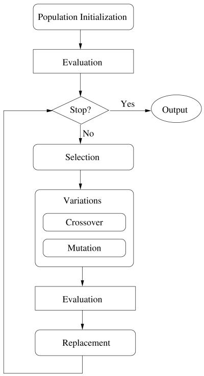
DE belongs to a class of population-based stochastic optimization methods, which share a common structure as illustrate in Fig. 1.
Fig. 1.
A general structure of evolution algorithms.
1) Vector Difference Operator
DE got its name from its special vector difference operator, which is of paramount importance to the algorithm. The vector difference operator has a very simple form [26], [29]:
| (12) |
where
U is the generated trial vector
r0 is the index of the base vector
r1 and r2 are the indices of the difference vectors
F is the difference scaling factor
The trial vector may replace a target vector with index i. Indices i, r0, r1, r2 must be mutually exclusive. The index i is selected in an ordered fashion from 1 to N. The base vector index r0 is selected in order from a permuted sequence τ = {1, …, N} − {i} and the difference vector indices r1, r2 are randomly selected from the set {1, …, N} − {i, r0}.
The control parameter of this operator is F, which determines how much perturbation of the vector difference to add to the base vector. F has an empirically determined bound between [0, 1], and should use a larger value with a smaller population size and vice versa.
Adding a scaled vector difference to the base vector unavoidably causes some trial vectors to violate the boundary constraints. In our BLT application, violating the boundary constraints means the source is outside the object, which leads to a failure in objective function evaluation. To keep the boundary constraints strict, we can apply a penalty or use a bounce-back mechanism. The penalty method discards the constraint-violated trial vector, while the bounce-back replaces it with a valid one. We prefer the latter boundary satisfaction strategy, because it will perform better sampling near the boundary. The bounce-back is given as [29]:
| (13) |
where
uj is the jth element of the trial vector U
xr0,j is the jth element of the base vector Xr0
xl,j is the lower bound of the jth element of a solution vector
xu,j is the upper bound
The beauty of this simple but powerful operator is that it can adjust the step size of the perturbation without additional computation or input. In the early stage of the optimization, the vector differences are large because of the wide spread population. As the search proceeds, the candidate solution vectors aggregate to promising areas in the search landscape, so the vector differences become smaller, and the vector difference operator becomes a fine-tuning operator. Such a spontaneous self-adaptation mechanism provides the DE algorithm with a balanced exploration/exploitation and high numerical precision.
2) Two-stage Crossover Scheme
DE could use several crossover schemes, such as binomial, exponential, or either-or [29]. In this paper, we adopt the most commonly used binomial crossover scheme, which is given by:
| (14) |
where
CR is the crossover rate
xj is the jth element in X
uj is the jth element in U
jrand is a randomly selected element index
Randomly picking an index jrand prevents the duplication of the target vector when a very low crossover rate is applied. The binomial crossover mutates the target vector: with zero crossover rate, only the jrandth element in the solution vector is mutated; with ~ 1 crossover rate, the target vector is almost entirely being replaced by the trial vector. The high crossover rate leads to better convergence behavior, but it could expedite the convergence so much that the search converges prematurely. In contrast, a low crossover rate is unlikely to experience stagnation, but the population takes longer to converge. To take advantages of both high and low crossover rates and minimize their shortcomings, we proposed a two-stage crossover scheme for the DE: in stage one, the algorithm operates with a low crossover rate, i.e. CR ≤ 0.2, for a certain number of generations, then the algorithm switches to a high crossover rate state, i.e. CR ≥ 0.8, which speeds up the convergence. The search is then terminated when majority, i.e. ≥ 95% of the population converges to a single point. The two-stage optimization is especially useful for highly multimodal landscapes, where an over-expedited convergence is often a premature one.
C. Number of Sources Estimation
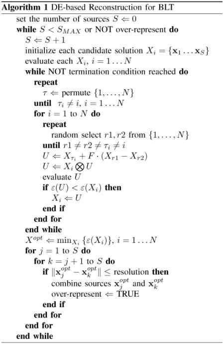
In previous sections we have assumed that the number of point sources used in the reconstruction is known. In some imaging applications, the number of sources can be estimated directly by biological means; in other cases, this information is unavailable. In this section, we present a method to estimate the number of sources from the reconstruction results iteratively. When the assumed number of point sources used in the reconstruction is slightly larger than the actual number of sources, several point sources will aggregate to represent a single point source, a this situation we call ‘over representation’. Given a desired spatial resolution, we are able to detect the overrepresented source as multiple point sources aggregate within the desired resolution and can be combined to a single source. The iterative process consists of performing a series of reconstructions with an increasing number of point sources; at the end of each reconstruction, if two or more sources are close enough, they are combined into a single source, hence the over representation is detected and the correct number of sources is determined. With this algorithm, The regularized BLT reconstruction only requires an user-determined spatial resolution for the image as additional a priori information. As a summary, the pseudocode of the DE-based reconstruction algorithm is provided in Algorithm 1. where
⊗ is the crossover operator
ε is the objective function
∥Xj − Xk∥ is the distance between source j and k
IV. Experiments and Results
In this section we investigate the accuracy and robustness of the proposed BLT model and reconstruction method using simulated measurement data. We also demonstrate its effectiveness using phantom data and apply the method to cancer cell imaging in vivo using firefly luciferase.
A. Numerical Studies
The numerical experiments are performed on an ellipsoidal digital phantom with a total length of 30 mm and maximum width of 14 mm; the geometrical center was located at the origin of Cartesian coordinates. The digital phantom was discretized into 7421 nodes and 38160 tetrahedra with an average edge length about 1.2 mm. The photon fluence rate on the boundary was generated using Monte Carlo (MC) simulation [30] and the value is recorded at every surface node of the discretized ellipsoid.
1) Reconstruction Accuracy
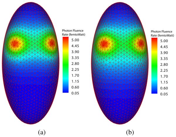
In the first set of experiments, we demonstrated the effectiveness of the source number determination method and the accuracy of the reconstruction. The optical parameters of the digital phantom were set to μa = 0.01 mm−1 and . We obtained two boundary measurements using two and three point sources, respectively. In the two-source case, the sources were located at (0.0, 5.0, 5.0) and (5.0, 0.0, 5.0) in Cartesian coordinates using mm units. In the three-source case, an additional source at (0.0, 0.0, 2.0) was included. All sources had an equal power of 0.314 picoWatt. The simulated measurements are shown in Fig. 2.
Fig. 2.
Simulated boundary photon fluence rate. (a) boundary photon fluence rate from two point sources; (b) boundary photon fluence rate from three point sources.
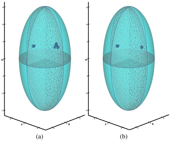
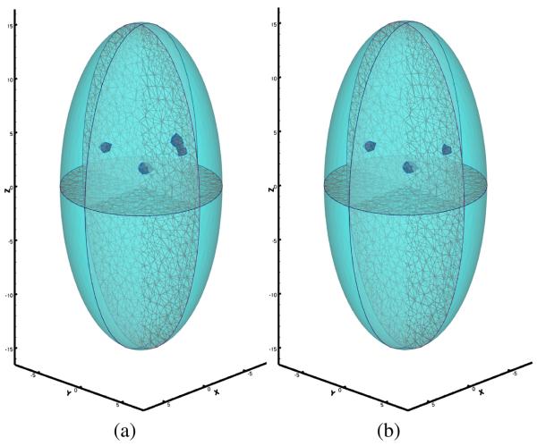
Note that not much difference between Fig. 2 (a) and Fig. 2 (b) can be directly observed, and the number of sources cannot be confidently estimated through the surface signal. We applied the proposed reconstruction method to recover the number of source, source locations and powers from the simulated surface measurement with a desired resolution of 1.6 mm. Fig. 3 (a) and Fig. 4 (a) show that extra sources aggregated around the true source location when the number of sources assumed in the reconstruction process was greater then the actual number. The aggregated sources were within the desired resolution, so they were combined. The number of point sources in both experiments were correctly identified. Fig. 3 (b) and Fig. 4 (b) show the final reconstruction results. The final reconstruction with the correct number of sources was able to represent the source distribution accurately within the desired resolution.
Fig. 3.
Reconstruction results of two bioluminescence sources. (a) two extra sources were assumed; (b) exact number of sources was used.
Fig. 4.
Reconstruction result of three bioluminescence sources. (a) one extra source was assumed; (b) exact number of sources was used.
The reconstructed point source positions and powers are listed in Table I and II for the two-source and three-source cases, respectively. The maximum error for source position was 0.6 mm and the maximum relative error for source power was 8%. The reconstruction used a population size of 100, a vector difference scale factor of 0.5, a low crossover rate of 0.2 for the first 100 generations, and a high crossover rate of 0.9 until convergence. The computation time was 30 and 45 seconds on a workstation with a 2.6 GHz Intel Xeon processor for the two-source and three-source cases, respectively.
TABLE I.
Reconstruction result for two bioluminescent point sources
| source # | x (mm) | y (mm) | z (mm) | power (picoWatt) |
|---|---|---|---|---|
| 1 | 0.098 | 5.029 | 4.584 | 0.336 |
| 2 | 4.500 | 0.159 | 4.925 | 0.293 |
TABLE II.
Reconstruction result for three bioluminescent point sources
| source # | x (mm) | y (mm) | z (mm) | power (picoWatt) |
|---|---|---|---|---|
| 1 | 0.098 | 5.029 | 4.584 | 0.329 |
| 2 | 4.500 | 0.159 | 4.925 | 0.301 |
| 3 | 0.074 | 0.552 | 1.785 | 0.289 |
2) Reconstruction Robustness
Aside from the reconstruction accuracy, we tested the reconstruction robustness against inaccurate optical parameters. In most BLT applications, the optical parameters of the biological tissues used in the reconstruction could have various degree of inaccuracy. Inaccurate tissue optical properties could affect the reconstruction accuracy significantly [31]. We investigated the impact of optical parameter variation on the proposed BLT model and DE-based reconstruction method by adding ±10% perturbation to absorption and reduced scattering coefficients in a Monte Carlo simulation. The simulations were performed on the same ellipsoidal digital phantom with two point sources at (0.0, 5.0, 5.0) and (5.0, 0.0, 5.0), and used similar settings as the previous analysis. The actual absorption coefficient and reduced scattering are μa = 0.01mm−1 and . The results (Table III and IV) show that the proposed method is robust against optical parameter perturbation, especially for source position.
TABLE III.
Effects of absorption variation on reconstruction results
| μa(mm−1) | 0.009 | 0.011 |
|---|---|---|
| source 1 position error (mm) | 0.82 | 0.43 |
| source 1 power error (%) | 17% | 13% |
| source 2 position error (mm) | 0.53 | 0.53 |
| source 2 power error (%) | 15% | 11% |
TABLE IV.
Effects of scattering variation on reconstruction results
| μ′s(mm−1) | 0.9 | 1.1 |
|---|---|---|
| source 1 position error (mm) | 1.42 | 0.43 |
| source 1 power error (%) | 23% | 19% |
| source 2 position error (mm) | 0.53 | 0.53 |
| source 2 power error (%) | 19% | 18% |
B. Phantom Study
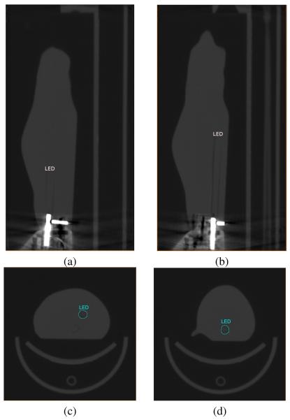
We demonstrated the effectiveness of the proposed reconstruction algorithm with a phantom experiment. The experiment was performed on a mouse-shaped phantom with two embedded LED sources, as shown in Fig. 5. The positions of the LEDs were revealed by CT scan of the phantom, shown in Fig. 6.
Fig. 5.
Mouse-shaped phantom from Xenogen Cooperation.
Fig. 6.
LEDs' positions in the phantom's CT scan images. (a) sagittal view of LED 1; (b) sagittal view of LED 2; (c) axial view of LED 1; (d) axial view of LED 2.
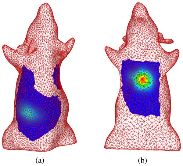
We performed the experiment using both LEDs as light sources. The LED near the neck had an intensity of 1.11 × 10¹¹ photons/second and the intensity of the LED at the abdomen was 1.25 × 10¹¹ photons/second. The surface photon fluence was measured using Xenogen's IVIS 100 series imaging system. A filter of 515-575 nm was used to limit the spectrum of the signal, and the corresponding optical parameters of the phantom were μa = 0.091 mm−1 and . In contrast to the popular four-views configuration for bioluminescence tomography [6], we only captured the measurements from dorsal and ventral views to demonstrate the robustness of the reconstruction. The surface measurements were normalized. A geometrical model of the phantom was constructed from the CT scan images using Amira (Visage Imaging, Inc.). The geometrical model was discretized into 14844 nodes and 75107 tetrahedra. The surface measurements were mapped to the boundary nodes of the model, as shown in Fig. 7.
Fig. 7.
Normalized surface photon fluence rate. (a) dorsal view; (b) ventral view.
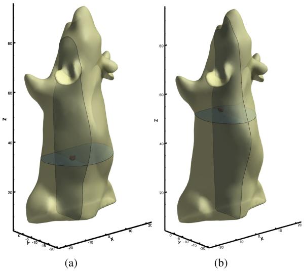
Using the same optimization parameter configuration presented in the numerical study section, the reconstruction took one minute and ten seconds on an Intel Xeon workstation. The reconstructed source locations are shown in Fig. 8. The difference between the reconstructed locations and the LED positions measured on the CT scan images were less then two mm, and the reconstructed source strength ratio was 1.52:1 for the LED in the abdomen region versus the one near the neck.
Fig. 8.
Reconstruction results of LED sources. (a) reconstructed location of LED 1; (b) reconstructed locations of LED 2.
C. In Vivo Experiment
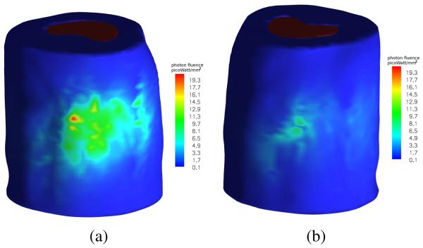
Finally, we applied the proposed method to detect tumors labeled with firefly luciferase reporters in a mouse study. Tumors were induced by injecting the 22Rv1-luciferase human prostate cancer cell line intracardially into SCID mice. After a few weeks, a cancer-bearing mouse was injected with D-luciferin at a dose of 100 μl per 10 g body weight. The surface photon emission of the bioluminescent reporters, as shown in Fig. 9, was captured using our in-house BLT system.
Fig. 9.
Surface photon fluence captured using in-house BLT system. (a) dorsal view; (b) ventral view.
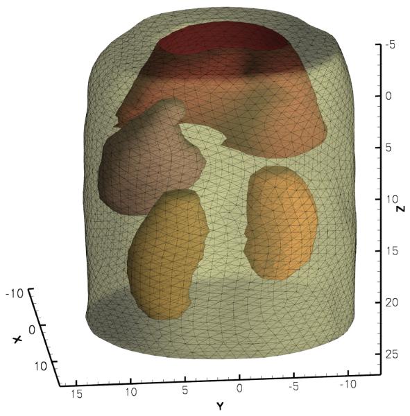
The mouse abdominal section was scanned using micro-CT and a finite element model that described the optical property heterogeneity was constructed from the CT image volume using Amira 4.1 (Visage Imaging, Andover, MA), as shown in Fig. 10. The model consisted of 15971 nodes and 87513 tetrahedral elements. The optical parameters of each organ are listed in Table V [32].
Fig. 10.
Finite element model of the abdominal section of the mouse.
TABLE V.
Optical parameters for mouse organs
| organs | μa(mm−1) | μ′s(mm−1) |
|---|---|---|
| muscle | 0.23 | 1.00 |
| liver | 0.45 | 2.00 |
| stomach | 0.21 | 1.70 |
| kidney | 0.12 | 1.20 |
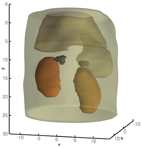
We set the population size to 150. The reconstruction took 1 minute and 40 seconds on a Intel Xeon workstation. Two tumors, located on top of the kidneys were found; the tumor locations are presented in Fig. 11. The reconstructed source powers are 14.4 nanoWatt for the bigger tumor and 8.6 nanoWatt for the small tumor. For verification, the mouse was dissected to located the tumors; one tumor was found on each adrenal gland with volumes of 468mm3 on the right and 275mm3 on the left, which had good agreement with the reconstruction. The reconstruction using the proposed method is also consistent with our previously published results [1].
Fig. 11.
Reconstructed adrenal gland tumors.
V. Discussions and Conclusion
In this manuscript, we proposed a regularized bioluminescence tomography model that incorporates the number of sources as a constraint and devise a scheme to determine the number of sources automatically. The regularized BLT model significantly reduced the number of variables in the optimization procedure, and more importantly produced a unique solution. Furthermore, we adapted the differential evolution method to solve this optimization in a two stage variation for efficient source reconstruction. The DE integrates the number of sources constraint directly into its versatile solution vector encoding scheme. DE also has the ability to locate the global optimum regardless of the initial values, and exhibits a fast and reliable convergence behavior.
Using numerical studies, we demonstrated that the proposed method is able to accurately localize and quantify light source distribution from noisy measurements and inaccurate optical parameters. The phantom study further demonstrated the robustness of the proposed method by locating the LED sources using measurements that only covered part of the surface. This result suggests that the proposed reconstruction method could reduce the imaging time and facilitate the hardware design. The in vivo study presented a practical example of the effectiveness of the method, and the result showed a good agreement with the histological verification along with consistency with the previously published results.
However, there are several major limitations to the proposed method. First, the optimization problem has a dimension that equals to four times the number of sources. The population size and generation of the optimization problem will increase rapidly as the dimensionality increases; therefore the DE optimization method is not suitable for the source distributions that need to be approximated by too many point sources. Second, although the regularized model is well applied to small isolated source reconstruction, the regularized model may not work well on distributed sources. The application of the proposed model to the distributed source is worth a systematic study in the future. Third, the iterative method for estimating the number of point sources needs to solve the reconstruction problem several times, and only one of the many reconstructions is used as the final result; therefore, when the number of sources cannot be determined from a priori knowledge, the computational efficiency will be greatly compromised. We also emphasize that our regularized BLT model is converted to an optimization with complex constraints. The resultant optimization problem cannot be adequately solved by a gradient-based optimization method; therefore, a fair comparison in performance between the DE-based method and the gradient-based method cannot be easily implemented.
Acknowledgment
The authors are thankful for the support by the following Grants: NIH/NIBIB EB001685, EB006036, EB008476, EB001458, NIH/NCI CA092865, CA135151, and DE-FC02-02ER63520
References
- 1.Wang G, Cong W, Durairaj K, Qian X, Shen H, Sinn P, Hoffman E, McLennan G, Henry M. In vivo mouse studies with bioluminescence tomography. Optics Express. 2006;14(17):7801–7809. doi: 10.1364/oe.14.007801. [DOI] [PubMed] [Google Scholar]
- 2.Li S, Driessen W, Sullivan S, Jiang H. Bioluminescence tomography based on phantoms with different concentrations of biolumines-cent cancer cells. Journal of Optics A: Pure and Applied Optics. 2006;8(9):743–746. [Google Scholar]
- 3.Kuo C, Coquoz O, Troy T, Xu H, Rice B. Three-dimensional reconstruction of in vivo bioluminescent sources based on multispectral imaging. Journal of Biomedical Optics. 2007;12:024007. doi: 10.1117/1.2717898. [DOI] [PubMed] [Google Scholar]
- 4.Contag C, Bachmann M. ADVANCES IN IN VIVO BIOLUMINESCENCE IMAGING OF GENE EXPRESSION. Annual Review of Biomedical Engineering. 2002;4(1):235–260. doi: 10.1146/annurev.bioeng.4.111901.093336. [DOI] [PubMed] [Google Scholar]
- 5.Rice B, Cable M, Nelson M. In vivo imaging of light-emitting probes. Journal of Biomedical Optics. 2001;6:432–440. doi: 10.1117/1.1413210. [DOI] [PubMed] [Google Scholar]
- 6.Wang G, Shen H, Durairaj K, Qian X, Cong W. The First Bioluminescence Tomography System for Simultaneous Acquisition of Multiview and Multispectral Data. International Journal of Biomedical Imaging. 2006;2006 doi: 10.1155/IJBI/2006/58601. [DOI] [PMC free article] [PubMed] [Google Scholar]
- 7.Welch A, Gemert M, et al. Optical-Thermal Response of Laser-Irradiated Tissue. Springer; 1995. [Google Scholar]
- 8.Arridge S, Hebden J. Optical imaging in medicine: II. Modelling and reconstruction. Phys. Med. Biol. 1997;42(5):841–853. doi: 10.1088/0031-9155/42/5/008. [DOI] [PubMed] [Google Scholar]
- 9.Klose A, Hielscher A. Optical tomography using the time-independent equation of radiative transferPart 2: inverse model. Journal of Quantitative Spectroscopy and Radiative Transfer. 2002;72(5):715–732. [Google Scholar]
- 10.Abdoulaev G, Hielscher A. Three-dimensional optical tomography with the equation of radiative transfer. Journal of Electronic Imaging. 2003;12:594–601. [Google Scholar]
- 11.Tarvainen T, Vauhkonen M, Kolehmainen V, Kaipio J. Finite element model for the coupled radiative transfer equation and diffusion approximation. Int. J. Numer. Methods Eng. 2006;65:383–405. [Google Scholar]
- 12.Klose A, Larsen E. Light transport in biological tissue based on the simplified spherical harmonics equations. Journal of Computational Physics. 2006;220(1):441–470. [Google Scholar]
- 13.Arridge S. Optical tomography in medical imaging. Inverse Problems. 1999;15(2):R41–R93. [Google Scholar]
- 14.Arridge S, Dehghani H, Schweiger M, Okada E. The finite element model for the propagation of light in scattering media: A direct method for domains with nonscattering regions. Medical Physics. 2000;27:252–264. doi: 10.1118/1.598868. [DOI] [PubMed] [Google Scholar]
- 15.Cong W, Wang G, Kumar D, Liu Y, Jiang M, Wang L, Hoffman E, McLennan G, McCray P, Zabner J, et al. Practical reconstruction method for bioluminescence tomography. Optics Express. 2005;13(18):6756–6771. doi: 10.1364/opex.13.006756. [DOI] [PubMed] [Google Scholar]
- 16.Chaudhari A, Darvas F, Bading J, Moats R, Conti P, Smith D, Cherry S, Leahy R. Hyperspectral and multispectral bioluminescence optical tomography for small animal imaging. Physics in Medicine and Biology. 2005;50(23):5421–5441. doi: 10.1088/0031-9155/50/23/001. [DOI] [PubMed] [Google Scholar]
- 17.Dehghani H, Davis S, Jiang S, Pogue B, Paulsen K, Patterson M. Spectrally resolved bioluminescence optical tomography. Optics Letters. 2006;31(3):365–367. doi: 10.1364/ol.31.000365. [DOI] [PubMed] [Google Scholar]
- 18.Cong A, Wang G. Multi-spectral bioluminescence tomography: Methodology and simulation. International Journal of Biomedical Imaging. 2006:1–7. doi: 10.1155/IJBI/2006/57614. [DOI] [PMC free article] [PubMed] [Google Scholar]
- 19.Soloviev V. Tomographic bioluminescence imaging with varying boundary conditions. Applied Optics. 2007;46(14):2778–2784. doi: 10.1364/ao.46.002778. [DOI] [PubMed] [Google Scholar]
- 20.Pogue B, Geimer S, McBride T, Jiang S, Osterberg U, Paulsen K. Three-dimensional simulation of near-infrared diffusion in tissue: boundary condition and geometry analysis for finite-element image reconstruction. Appl. Opt. 2001;40(4):588–600. doi: 10.1364/ao.40.000588. [DOI] [PubMed] [Google Scholar]
- 21.Schweiger M, Arridge S, Hiraoka M, Delpy D. The finite element method for the propagation of light in scattering media: Boundary and source conditions. Medical Physics. 1995;22:1779–1792. doi: 10.1118/1.597634. [DOI] [PubMed] [Google Scholar]
- 22.Arridge S, Schweiger M, Hiraoka M, Delpy D. A finite element approach for modeling photon transport in tissue. Medical Physics. 1993;20:299–309. doi: 10.1118/1.597069. [DOI] [PubMed] [Google Scholar]
- 23.Lv Y, Tian J, Cong W, Wang G, Luo J, Yang W, Li H. A multilevel adaptive finite element algorithm for bioluminescence tomography. Optics Express. 2006;14(18):8211–8223. doi: 10.1364/oe.14.008211. [DOI] [PubMed] [Google Scholar]
- 24.Jiang M, Zhou T, Cheng J, Cong W, Wang G. Image reconstruction for bioluminescence tomography from partial measurement. Optics Express. 2007;15(18):11 095–11 116. doi: 10.1364/oe.15.011095. [DOI] [PubMed] [Google Scholar]
- 25.Wang G, Li Y, Jiang M. Uniqueness theorems in bioluminescence tomography. Medical Physics. 2004;31:2289–2299. doi: 10.1118/1.1766420. [DOI] [PubMed] [Google Scholar]
- 26.Feoktistov V. Differential Evolution: In Search of Solutions. Springer; 2006. [Google Scholar]
- 27.Vesterstrom J, Thomsen R. A comparative study of differential evolution, particle swarm optimization, and evolutionary algorithms on numerical benchmark problems; Evolutionary Computation, 2004; 2004. CEC2004. Congress on. [Google Scholar]
- 28.Penev K, Littlefair G. Free Search - a comparative analysis. Information Sciences. 2005;172(1-2):173–193. [Google Scholar]
- 29.Price K, Storn R, Lampinen J. Differential Evolution: A Practical Approach to Global Optimization. Springer; 2005. [Google Scholar]
- 30.Wang L, Jacques S, Zheng L. MCMLMonte Carlo modeling of light transport in multi-layered tissues. Computer Methods and Programs in Biomedicine. 1995;47(2):131–146. doi: 10.1016/0169-2607(95)01640-f. [DOI] [PubMed] [Google Scholar]
- 31.Alexandrakis G, Rannou F, Chatziioannou A. Effect of optical property estimation accuracy on tomographic bioluminescence imaging: simulation of a combined optical-PET (OPET) system. PHYSICS IN MEDICINE AND BIOLOGY. 2006;51(8):2045–2053. doi: 10.1088/0031-9155/51/8/006. [DOI] [PMC free article] [PubMed] [Google Scholar]
- 32.Cheong W, Prahl S, Welch A. A review of the optical properties of biological tissues. IEEE Journal of Quantum Electronics. 1990;26(12):2166–2185. [Google Scholar]


