Abstract
Properties that can now be achieved with advanced, blue indium gallium nitride light emitting diodes (LEDs) lead to their potential as replacements for existing infrastructure in general illumination, with important implications for efficient use of energy. Further advances in this technology will benefit from reexamination of the modes for incorporating this materials technology into lighting modules that manage light conversion, extraction, and distribution, in ways that minimize adverse thermal effects associated with operation, with packages that exploit the unique aspects of these light sources. We present here ideas in anisotropic etching, microscale device assembly/integration, and module configuration that address these challenges in unconventional ways. Various device demonstrations provide examples of the capabilities, including thin, flexible lighting “tapes” based on patterned phosphors and large collections of small light emitters on plastic substrates. Quantitative modeling and experimental evaluation of heat flow in such structures illustrates one particular, important aspect of their operation: small, distributed LEDs can be passively cooled simply by direct thermal transport through thin-film metallization used for electrical interconnect, providing an enhanced and scalable means to integrate these devices in modules for white light generation.
Keywords: gallium nitride, solid-state lighting, transfer printing
Indium gallium nitride-based (InGaN) blue light emitting diodes (LEDs) hold a dominant position in the rapidly growing solid-state lighting industry (1, 2). The materials and designs for the active components of these devices are increasingly well developed due to widespread research focus on these aspects over the last one and a half decades. Internal and external quantum efficiencies of greater than 70% (3) and 60% (3), respectively, with luminous efficacies larger than 200 lm /W (4) and lifetimes of > 50,000 h (5) are now possible. The efficacies (i.e., 249 lm /W), exceed those of triphosphor fluorescent lamps (i.e., 90 lm /W), thereby making this technology an appealing choice for energy-efficient lighting systems (4). In particular, electricity consumption for lighting potentially could be cut in half using solid-state lighting (2). Although there remain opportunities for further improvements in these parameters, the emergence of LEDs into a ubiquitous technology for general illumination will rely critically on cost effective techniques for integrating the active materials into device packages, interconnecting them into modules, managing the accumulation of heat during their operation, and spatially homogenizing their light output at desired levels of chromaticity. Existing commercial methods use sophisticated, high-speed tools, but which are based on conceptually old procedures that exploit robotic systems to assemble material mechanically diced from a source wafer, with collections of bulk wires, lenses, and heat sinks in millimeter-scale packages, on a device-by-device basis, followed by separate steps to form integrated lighting modules (6). The intrinsic features of such processes prohibit cost competitive realization of some of the most appealing configurations of LEDs for lighting, such as those that involve large collections of ultrasmall, thin devices distributed uniformly, but sparsely, over emissive areas of large modules that could serve as direct replacements for troffers currently used in fluorescent building lights. Alternative techniques, such as those that use directed assembly of solution suspensions of LEDs, first reported nearly twenty years ago (7), appear interesting, but efforts to design commercially relevant manufacturing schemes have been unsuccessful. Here we describe a set of procedures that aims to address the limitations of existing approaches in a different way, using ideas that extend our recent work in flexible electronics (8), information display (9), and photo-voltaics (10, 11), to the area of solid-state lighting by introducing new materials, etching strategies, interconnection methods, thermal management techniques, and schemes for wavelength conversion and light distribution. The process begins with removal of InGaN epitaxial material grown on silicon wafers with (111) orientation, using lithographically defined structures and anisotropic wet chemical etching, in ways that bypass conventional laser lift-off techniques and wafer dicing. When implemented with fully formed LEDs, these ideas can be combined with deterministic assembly via transfer printing (12) to allow high-throughput manipulation of devices with geometries that are orders of magnitude smaller than those compatible with robotic pick-and-place procedures. Self-aligned techniques for thin-film metallization that exploit the large band-gap of GaN provide remarkably simple routes to interconnect large collections of devices. The outcome consists of finely distributed sources of illumination that naturally manage the thermal aspects of operation through dramatically accelerated rates for passive heat spreading, consistent with analytical models for heat flow. Laminating such systems with patterned layers of phosphors and film-type optical diffusers yields thin, flexible lighting modules whose formats make them attractive for wide ranging applications in general illumination, both conventional and unconventional.
Results
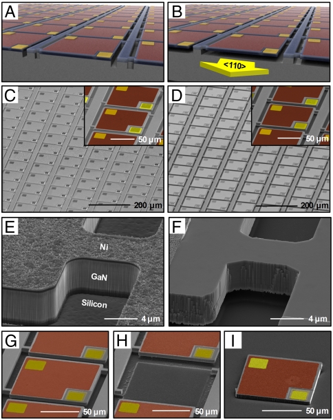
The work focuses on model multilayer InGaN epitaxial stacks grown on Si wafers with (111) orientation (13), due to the cost and throughput advantages that are expected to result from this materials technology when optimized to offer levels of quality (e.g., threading dislocation densities < 109 cm-2) (13) currently available from material grown on conventional substrates such as sapphire or SiC. The layer configurations appear in Fig. S1. As illustrated in Fig. S2, lithographically patterned n-type ohmic contacts (Ti:15 nm/Al:60 nm/Mo:20 nm/Au:100 nm) (14) result from electron beam (e-beam) evaporation and rapid thermal annealing (RTA, in N2 ambient) of metal deposited on regions of n-GaN exposed by inductively coupled plasma reactive ion etching (ICP-RIE). Similar procedures yield partially transparent p-type ohmic contacts (Ni:10 nm/Au:10 nm) to the top p-GaN layer, as shown in Fig. S3. Opaque pads (Ti:10 nm/Au:120 nm) e-beam evaporated on top of the p- and n- contacts enable single-step planarization and self-aligned passivation, using procedures outlined subsequently. Etching by ICP-RIE (i.e., mesa etch) defines the lateral dimensions of individual devices, in densely packed, arrayed layouts. Etching proceeds through the entire thickness of the InGaN material, and to a controlled depth (∼1 μm) into the silicon for purposes of release described next. A representative array of such devices appears in graphic illustration in Fig. 1A, and in a corresponding scanning electron microscope (SEM) image in Fig. 1C.
Fig. 1.
Schematic illustration of arrays of InGaN μ-ILED arrays (A) before and (B) after anisotropic etching of the near-interfacial region of a supporting Si (111) wafer. The colors correspond to the InGaN (light blue), the contact pads (gold), and a thin current spreading layer (red). SEM images of a dense array of μ-ILEDs on a Si (111) wafer (C) before and (D) after this type of anisotropic etching process. The insets provide magnified views (colorized using a scheme similar to that in A). SEM images of the region of the μ-ILED structure that connects to the underlying silicon wafer (E) before and (F) after etching. Break-away anchors serve as fracture points during retrieval of μ-ILEDs from Si (111) wafer. SEM images of a representative μ-ILED, shown in sequence, (G) after undercut, (H) after removal from the Si wafer, and (I) after assembly onto a receiving substrate (colorized for ease of viewing).
The procedure for releasing these devices from the underlying substrate exploits the large differences in rates (> 100×) (15, 16) for removing planes of Si(110) compared to Si(111) with wet chemical etching baths of potassium hydroxide (KOH) or tetramethylammonium hydroxide. To take advantage of this effect, the arrays are configured such that two sides of each device lie perpendicular to 〈110〉. The devices are tightly packed in this direction (i.e., spacing of 10 μm for this example, but with values that can be as small as 2 μm), and somewhat less so in the orthogonal direction (i.e., 40 μm shown here). Immersion in a hot, aqueous solution of KOH rapidly removes silicon along the Si(110) planes exposed by the mesa etch, thereby undercutting the devices without etching into the depth of the silicon wafer. Because the etching proceeds only along 〈110〉, relief structures of silicon remain in the orthogonal (〈111〉) direction between devices. A pair of small supporting structures (i.e., anchors) of GaN, also defined during the mesa etch, connects each of the devices to the silicon in these regions (i.e., anchor bars), to yield freely suspended configurations after the KOH etching self-terminates on the (111) planes. A graphical illustration and corresponding SEM image appear in Fig. 1 B and D, respectively. Fig. 1 E and F show magnified views of the anchor regions before and after anisotropic silicon etching. At this stage, the devices can be removed, in a nondestructive, high-speed and parallel operation, using soft stamps and the techniques of transfer printing (12). In this way, assembly into arrayed layouts on glass, plastic, or other classes of substrate can be achieved at room temperature, with throughputs of millions of devices per hour and micron-scale positioning accuracy, in deterministic and adjustable ranges of pitch (Fig. S4) (9) over areas that can be much larger than those defined by the devices on the source wafer. The SEM images of Fig. 1 G–I show a progression of a representative device from delineation on a donor substrate, to removal and delivery onto a receiving substrate, respectively. The LEDs formed in this manner have emission areas and thicknesses that can be up to 1,600× and 100× smaller, respectively, than conventional devices (i.e., 1 × 1 mm2). For these reasons, we refer to the devices as microscale inorganic light emitting diodes (μ-ILEDs), following previous reports on different materials systems (9, 17).
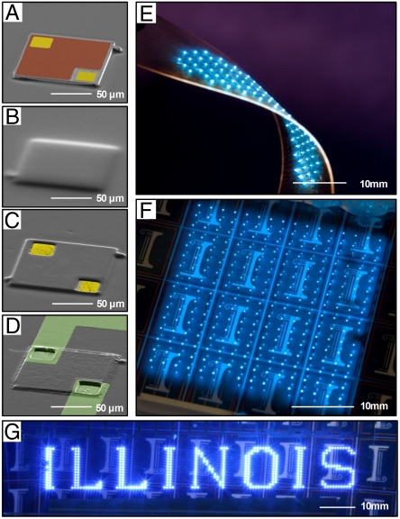
The small thicknesses of μ-ILEDs make them amenable to interconnect based on thin-film metallization, to provide a high-speed, parallel alternative to traditional wire bonds. Practical challenges exist for applications in lighting, however, due to requirements on overlay and registration, especially for large area modules (i.e., troffer-scale). Fortunately, the properties of GaN devices allow a remarkably simple method for accomplishing precise registration, without the need for lithographic alignment or photo-resist processing. In this “back-side exposure” (BSE) technique, both planarization and via formation occur simultaneously in a single-step, self-aligned process. Here, the device structures themselves serve as a mask for photoinduced crosslinking of a polymer overcoat (Fig. S5). Fig. 2A shows an SEM image of a single 100 × 100 μm2 μ-ILED printed on a glass substrate. Spin-coating a photosensitive polymer [Dow Chemical, Benzocyclobutene (BCB), Cyclotene 4024-40 Resin] fully encapsulates the device (Fig. 2B). H-line radiation incident on the backside of the structure passes through the transparent substrate (e.g., glass or plastic) and the GaN (band gap ≈3.4 eV), to flood expose the polymer in all regions except those shadowed by the opaque contact pads, shown in colorized gold in Fig. 2C. Washing away the unexposed regions leaves a pattern of polymer with openings at the contacts, and with positively sloped sidewalls for conformal deposition of interconnect metal (Fig. 2D). Due to the encapsulating nature of the polymer coating, requirements on registration for the interconnects are greatly relaxed compared to those for the contact pads themselves. In particular, the relevant length scale for registration decreases from roughly the size of a contact pad to the size of an entire device. This improvement corresponds to a factor of four for the case considered here with 25 × 25 μm2 contact pads, but could be as large as a factor of 20 with 5 × 5 μm2 contact pads. As shown in Fig. 2D, we purposefully interconnected arrays with overly wide leads (which we find easily accommodates small misalignments in the printed location of devices) by edge-over metallization, photolithographic patterning, and subsequent metal etching. This method is amenable to interconnecting large numbers of μ-ILEDs over large area arrays (e.g., 396 μ-ILEDs over ∼12 cm2 in Fig. 2G), shown here for arrays integrated on polyethylene terephthalate (PET) (Fig. 2E) and on glass (Fig. 2 F and G) substrates, and for exceptionally small devices. As an example of the latter capability, we could easily form vias of ∼4 × 4 μm2 on devices with lateral dimensions as small as 25 × 25 μm2 (Fig. S5D).
Fig. 2.
SEM images of the interconnection process for a representative InGaN μ-ILED, shown in sequence, (A) after assembly onto a optically transparent substrate (e.g., glass or plastic), (B) after spin-coating a photo-sensitive polymer, (C) after self-aligned via formation using a BSE process, and (D) after deposition and patterning of a metallic interconnect layer. The colorized regions correspond to the contact pads (gold), a thin current spreading layer (red), and Al interconnects (green). Optical images of various lighting modules based on arrays of μ-ILEDs (E) plastic and (F, G) glass substrates.
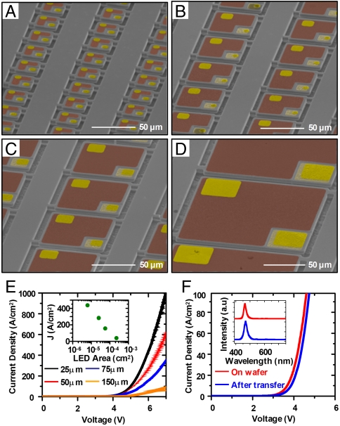
To illustrate the versatility, Fig. 3 A–D show SEM images of exemplary μ-ILEDs with various sizes from (A) 25 × 25 μm2, (B) 50 × 50 μm2, (C) 75 × 75 μm2, and (D) 150 × 150 μm2. The sizes of the smallest and largest devices are limited by the resolution in device processing (i.e., lithography and mesa etching) and by degradation of etch-resist layers during silicon etching, respectively. The current density-voltage (J-V) characteristics of these μ-ILEDs show a noticeable increase in J as the size of μ-ILEDs decreases (Fig. 3E). This behavior might be attributed to superior current spreading in small devices (18). The properties are unaltered by the processing, as shown in Fig. 3F. The small, thin geometries also provide enhanced mechanical bendability (Fig. S6) (19) and dramatically improved rates for passive thermal spreading. Both of these qualities facilitate integration with flexible sheets of plastic, as shown in Fig. 2E. Details related to the bending mechanics appear in the SI Text; the thermal properties represent a focus of the Discussion section.
Fig. 3.
SEM images of arrays of released InGaN μ-ILEDs with dimensions from (A) 25 × 25 μm2, (B) 50 × 50 μm2, (C) 75 × 75 μm2 to (D) 150 × 150 μm2. The colorized regions correspond to the contact pads (gold), and thin current spreading layers (red). (E) Corresponding current density-voltage (J-V) characteristics for μ-ILEDs with the dimensions shown in (A). The inset provides a plot of current density as a function of μ-ILED area, measured at 6 V. (F) Current density-voltage (J-V) characteristics and emission spectrum (inset) of a representative device before undercut etching on the Si wafer, and after assembly onto a glass substrate.
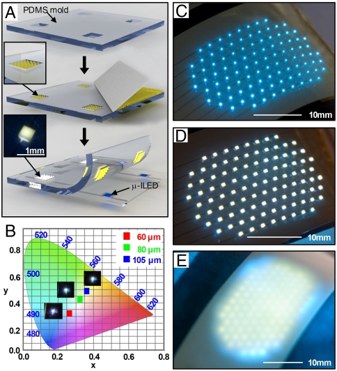
To demonstrate integrated sources of white light that exploit these unique capabilities, we developed schemes for integrating phosphors, patterned into small tiles, with arrays of μ-ILEDs and thin-film optical diffusers. As an example, we built a flexible lighting device that incorporates an amount of active material equal to that of a single, conventional 1 × 1 mm2 LED, but spread sparsely across an area of ∼300 mm2 at an areal coverage corresponding to ∼0.3% to optimize the thermal and optical properties (Fig. 4, Fig. S7). The process for constructing these systems follows two parallel routes: (i), μ-ILED fabrication, array assembly, and interconnection as shown in Fig. S2 using a thin, PET substrate similar to the one in Fig. 2, but with interconnects patterned such that 90% of each device is covered by reflective metal (Ti:3 nm/Al:500 nm), and the remaining 10% comprises the separation of leads to the p- and n- contacts; and, (ii), generation of a separate, patterned array of phosphor tiles matching the spatial geometry of the printed devices, on a soft, flexible sheet of the elastomer poly(dimethylsiloxane) (PDMS). The design of this second submodule is important because it allows the use of phosphor only where required, i.e., directly above each of the μ-ILEDs in the array. A schematic representation of the processing steps appears in Fig. 4A. The substrate consists of a thin sheet of PDMS embossed with an array of square wells of relief. A slurry incorporating a cerium-doped yttrium aluminum garnet phosphor (Intematix, NYAG-1) in an uncured PDMS matrix uniformly disperses the phosphor particles (Fig. S8), in a manner that allows their delivery to the wells using a doctor blade. Thermally curing the slurry completes this part of the fabrication process. Soft contact lamination against a patterned, interconnected array of μ-ILEDs yields white light output, with chromaticity that can be tuned by controlling the well depth using slurries at a constant phosphor-in-PDMS weight loading (37.35 wt%). Chromaticity data at different phosphor thicknesses appear in an International Commission on Illumination (CIE) 1931 color space diagram in Fig. 4B. As expected, the chromaticity follows an approximately linear path between the limits of the blue emission of the μ-ILED and yellow emission of the phosphor with increasing thickness. For this PDMS-phosphor composition we obtain CIE coordinates of x = 0.321 and y = 0.376 with a phosphor thickness of 80 μm.
Fig. 4.
(A) Schematic illustration of the process for fabricating flexible, white lighting modules, achieved by integrating patterned, encapsulated tiles of YAG:Ce phosphor islands with arrays of InGaN μ-ILEDs. (B) Color chromaticity plotted on a CIE 1931 color space diagram for μ-ILEDs integrated with phosphors with thicknesses of 60 μm, 80 μm, and 105 μm. Optical images of a fully interconnected array of μ-ILEDs (C) without phosphor, (D) with a laminated film of encapsulated YAG:Ce phosphor islands (500 × 500 μm2), and (E) with a laminated diffuser film.
The LED component of the system consists of 100 μ-ILEDs, each 100 × 100 μm2, in a hexagonal array, printed with an interdevice spacing of 2 mm, set to exceed the characteristic thermal diffusion length in this system. Fig. 4 C and D shows images of the array before and after lamination against a sheet of patterned phosphor, respectively. (In this layout, the PET substrate provides a spacer between the μ-ILEDs and the phosphor tiles.) To complete the fabrication, a thin plastic diffuser film laminates onto the array to achieve diffuse, larger area emission, as in Fig. 4E. This sparse array of printed μ-ILEDs provides an effective illuminated area > 100 times larger than the area of a traditional LED die, in a way that uses the same amount of InGaN in a configuration that has strong optical and thermal benefits.
Discussion
The thermal benefits of the type of layout in Fig. 4 are critically important, due to the adverse effects of excessive heating that can occur in devices with conventional sizes (e.g., 1 × 1 mm2) in the absence of bulk, or miniature, heat sinking structures (20, 21). Quantitative study shows that for the sparse, μ-ILED designs, the electrical interconnects serve simultaneously as effective heat sinks. We examine the system using both analytical treatments and rigorous finite element methods (FEM) simulations. For the former, the approximately axi-symmetric nature of the system allows a precise analytical study of the thermal transport properties. The heat source is modeled as a disk with a radius r0, and total heat generation Q, which is approximately equal to the input power to the μ-ILED that does not result in light emission (22). The temperature distribution is obtained from the steady-state heat transfer governing equation  in cylindrical coordinates (r, z) (Fig. S9). The boundary conditions include the free convection
  at the top (air-interconnect) surface, and constant temperature T = T∞ at the bottom (glass) surface, where h is the coefficient of natural convection. The continuity of temperature and heat flux across the interconnect-BCB interface requires [T] = 0 and
  , where [] stands for the discontinuity between two adjacent layers. The above continuity conditions also hold at other interfaces. Heat generation requires
  across the top and bottom surfaces of the μ-ILED. The interconnect surface temperature is obtained as (see SI Text for details)
 |
[1] |
where
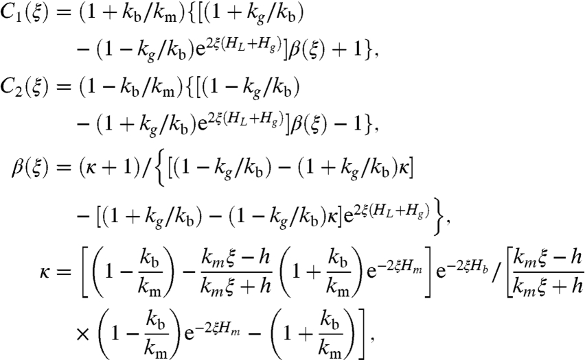 |
with J0 and J1 being the Bessel functions of order 0 and 1, respectively. The operating μ-ILED temperature is given by
 |
[2] |
This analytical treatment agrees well with full three-dimensional FEM simulations as shown in Fig. S10D. The differences between temperatures in Eqs. 1 and 2 and FEM simulations are less than 3% for μ-ILED sizes from 10 μm to 100 μm with a 1,000 nm-thick interconnect at a power density 400 W/cm2. The coefficient of natural convection is h = 25 W/m2/°C (23). Other conditions in experiments include the surrounding temperature T∞ = 50 °C, thickness and thermal conductivity Hb = 1 μm, kb = 0.3 W/m/°C for BCB (24); Hg = 800 μm, kg = 1.1 W/m/°C for glass (25); and HL = 5 μm for μ-ILED. The thermal conductivity for Al interconnects is thickness dependent (26–29), and is taken as 70 W/m/°C and 160 W/m/°C for 300 nm-thick and 1,000 nm-thick interconnects, respectively. The radius of the disk heat source is r0 = 56 μm to yield the same area as the square μ-ILED with dimensions of 100 × 100 μm2.
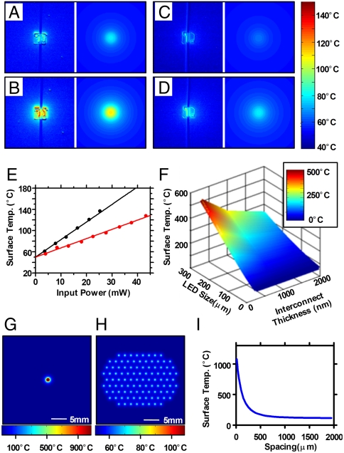
The left and right frames of Fig. 5 A–D show a set of experiments involving infrared thermal imaging of temperature distributions (QFI Infra-Scope Micro-Thermal Imager) and analytical predictions, respectively. These experiments compare surface temperatures for cases of Al interconnects with thicknesses of 300 nm and 1,000 nm (Fig. 5 A–B for 300 nm and Fig. 5 C–D for 1,000 nm), for input power ranging from 7.8 mW to 43.2 mW (i.e., power density ranging from 78 W/cm2 to 432 W/cm2). Fig. 5E presents surface temperatures as a function of power, where analytical model results (lines) agree very well the experimental measurements (symbols) for devices with these two interconnect thicknesses.
Fig. 5.
(A–D) Temperature distributions for isolated InGaN μ-ILEDs with Al interconnects [300 nm and 1,000 nm-thick for (A–B) and (C–D), respectively] at input powers of (A) 7.8 mW, (B) 16.4 mW, (C) 8.4 mW, and (D) 18.0 mW captured using a QFI Infra-Scope Micro-Thermal Imager (left) and calculated by analytical models (right). (E) Surface temperature for μ-ILEDs with Al interconnect thicknesses of 300 nm (black) and 1,000 nm (red) extracted from experiments (dots) and computed using the analytical model (lines) as a function of input power. (F) Three-dimensional plot of the surface temperature as function of device size and interconnect thickness, at a constant heat flux of 400 W/cm2. Temperature distribution for (G) a macrosize LED (i.e., 1 × 1 mm2), and (H) an array of 100 μ-ILEDs (i.e., 100 × 100 μm2) at a spacing of 2 mm. (I) μ-ILEDs surface temperature vs. spacing for an array of 100 μ-ILEDs.
The results of Fig. 5 A–E clearly show pronounced decreases in the temperatures with thicker Al interconnects, thereby demonstrating that the interconnects themselves serve a dual role as efficient heat sinks by accelerating the rates of lateral thermal diffusion. These effects can be attributed predominantly to the significant thermal mass of the interconnects compared to the μ-ILEDs, and to their higher thermal conductivities. As a consequence, both the thickness of the interconnects and the size of the devices are important. A theoretical parametric study, summarized in Fig. 5F, shows the surface temperatures at a constant heat flux density of 400 W/cm2, as a function of these two variables. Clearly, the temperature can be greatly reduced by decreasing the sizes of the LEDs and by increasing the thicknesses of the interconnects. As a particular example, consider a conventional, macrosize LED (i.e., 1 × 1 mm2) and an array of 100 μ-ILEDs (i.e., 100 × 100 μm2) at a spacing of 2 mm on otherwise identical platforms, both at total input power densities of 400 W/cm2. The method of superposition is used to determine the temperature of μ-ILED arrays based on the solution for a single LED, i.e.,  , where Ti(r,z) is the temperature distribution due to ith μ-ILED. The surface temperature distributions for a macrosize LED and μ-ILED array with spacing 2 mm are shown in Fig. 5 G and H, respectively. The maximum temperature occurs at the center of the array and it decreases with increasing spacing (Fig. 5I). The conventional LED would reach a temperature of over 1,000 °C whereas the array of μ-ILEDs would operate at ∼100 °C (Fig. S10D). In real devices, the conventional LED would be completely destroyed under these conditions, thereby motivating the requirement for advanced heat sinking structures of the type that are presently in use commercially. By contrast, the μ-ILEDs experience temperatures that enable stable operation, without any additional components.
Conclusions
The strategies reported here incorporate advanced ideas in etching to release thin devices, self-aligned photoexposures to form metal features that serve simultaneously as electrical interconnects and thermal heat spreaders, and module designs that include thin, patterned phosphors with film diffusers. This collection of procedures, combined with analytical models of heat flow, create new design opportunities in solid-state lighting. Although all of these processes were combined to yield integrated systems, each can be implemented separately and matched to existing techniques for certain steps, to add new capabilities to otherwise conventional module designs. For example, the same concepts can be applied to active materials derived from epitaxial growth on sapphire substrates. These and other possibilities might represent interesting directions for future work.
Materials and Methods
Fabrication of GaN μ-ILEDs.
A GaN/Si(111) wafer (Azzurro Semiconductor) with layers of GaN:Mg (110 nm), five repeats of InGaN/GaN:Si (3 nm:10 nm), GaN:Si (1,700 nm), AlN:Si/GaN:Si (1,900 nm), GaN (750 nm), and AlN/AlGaN (300 nm) served as the starting material. Multiple metal layers (Ti:15 nm/Al:60 nm/Mo:20 nm/Au:100 nm) are deposited via e-beam evaporator on regions of n-GaN exposed by ICP-RIE etching and annealed at 860 °C for 30 s in N2 ambient to form n-type ohmic contact to GaN:Si layer. For p-type ohmic contact to GaN:Mg layer, metal layers (Ni:10 nm/Au:10 nm) are deposited via e-beam evaporator and annealed at 500 °C for 10 min in air ambient. Next, opaque contact pads are formed by e-beam evaporation (Ti:10 nm/Au:120 nm). As a resist for KOH attack on ohmic contacts, a 300 nm layer of silicon nitride was deposited by plasma enhanced chemical vapor deposition. The geometry of the device array was photo-lithographically defined by patterning a metal etch mask of metal (Ti:50 nm/Ni:450 nm) by photo-resist lift-off process then removing the exposed silicon nitride by RIE with SF6. An ICP-RIE step provided the mesa etch, to generate an isolated array of devices. Anisotropic undercut etching of the silicon was performed by complete immersion in a solution of KOH (PSE-200, Transene) at 100 °C (hot plate temperature).
Fabrication of Arrays of InGaN μ-ILEDs.
Devices were transfer printed from the source wafer to a target substrate, using procedures described elsewhere. BSE was performed by spin-casting and prebaking a layer of benzocyclobutene (Cyclotene 4024-40 Resin, 2,000 rpm for 60 sec, 80 °C for 2 min). Samples were inverted, placed on a Cr-coated glass slide, exposed under a MJB3 Mask Aligner (Karl Suss), then developed (DS2100). After curing (210 °C for 60 min in O2-free environment), interconnect metal (Ti/Al in desired thickness) was sputtered and patterned by photolithography and metal etching [Ti-6:1 BOE, Al-Al Etchant Type A (Transene)].
Fabrication of Thin, Flexible, White Light Modules.
Fabricating supports for the phosphor involved casting and curing PDMS (10∶1 mixture of base to curing agent) against a functionalized silicon wafer (trichlorosilane, United Chemical Technologies) with a photodefined set of structures of epoxy (SU-8 50, MicroChem Corp.) with desired thicknesses. Peeling away the cured PDMS yielded an array of relief features (500 × 500 μm2) matching the spatial geometry of interconnected μ-ILEDs. Phosphor islands were created by scraping a PDMS-based slurry of phosphor (NYAG-1, Intematix, created by mixing with uncured PDMS) across the PDMS substrate using a doctor-blade type implement consisting of a PDMS-coated razor blade. Thermal curing (70 °C for > 3 h) completed the process. The phosphor mold was manually aligned and laminated to a matching array of μ-ILEDs. The module was completed by bonding an optical diffuser film (AX27425, Anchor Optics) to the phosphor mold.
Characterization of Electrical, Optical, Mechanical, and Thermal Properties.
Electrical measurements were performed with a semiconductor parameter analyzer (4155C, Agilent or 2400 Sourcemeter, Keithley). Optical measurements of the emission spectra were performed with a high resolution spectrometer (HR4000, Ocean Optics). Color chromaticity was determined using SpectraSuite (Ocean Optics) with a radiometric calibration source (HL-2000, Mikropack) and an Ocean Optics spectrometer optical fiber in a fixed location, ∼1 mm, above the sample. Bending measurements involved determining the forward voltage needed to produce 10 mA current with the sample mounted on cylindrical tubes with various radii, ranging from 5.9 mm to 65.3 mm. Fatigue measurements were performed by repeatedly bending the specimen from a flat state to the bent state with a bending radius of 5.9 mm. Thermal measurements of the surface temperature of μ-ILEDs were performed using MWIR-based InSb thermal imager (InfraScope, QFI) with the base temperature of 50 °C.
Supplementary Material
Acknowledgments.
We thank S. Elgan and N. Ahmed for help in transfer-printing using an automated printing tool. We also thank E. Chow for thermal imaging and L. Shi’s help on the finite element modeling of the system. This material is based partly upon work supported by the Department of Energy, Division of Materials Sciences under Award No. DEFG02-91ER45439, through the Frederick Seitz MRL and Center for Microanalysis of Materials at the University of Illinois at Urbana-Champaign. For automated printers, the authors acknowledge the center for Nanoscale Chemical Electrical Mechanical Manufacturing Systems in University of Illinois, which is funded by National Science Foundation under grant DMI-0328162.
Footnotes
The authors declare no conflict of interest.
This article is a PNAS Direct Submission.
This article contains supporting information online at www.pnas.org/lookup/suppl/doi:10.1073/pnas.1102650108/-/DCSupplemental.
References
- 1.Tsao JY, Coltrin ME, Crawford MH, Simmons JA. Solid-state lighting: an integrated human factors, technology, and economic perspective. Proceedings of the IEEE. 2010;98:1162–1179. [Google Scholar]
- 2.Schubert EF, Kim JK. Solid-state light sources getting smart. Science. 2005;308:1274–1278. doi: 10.1126/science.1108712. [DOI] [PubMed] [Google Scholar]
- 3.Chen G, et al. Performance of high-power III-nitride light emitting diodes. Physica Status Solidi (a) 2008;205:1086–1092. [Google Scholar]
- 4.Narukawa Y, Ichikawa M, Sanga D, Sano M, Mukai T. White light emitting diodes with super-high luminous efficacy. J Phys D Appl Phys. 2010;43:354002. [Google Scholar]
- 5.US Department of Energy. Washington, DC: US DoE; 2010. Solid-state lighting research and development: Multi-year program plan) Available from http://www1.eere.energy.gov/buildings/ssl/techroadmaps.html. [Google Scholar]
- 6.Karlicek RF., Jr High power LED packaging; Conference on Lasers and Electro-optics (CLEO); MD: IEEE; 2005. pp. 337–339. [Google Scholar]
- 7.Yeh H-JJ, Smith JS. Fluidic self-assembly for the integration of GaAs light-emitting diodes on Si substrates. IEEE Photonic Tech L. 1994;6:706–708. [Google Scholar]
- 8.Kim D-H, et al. Materials and noncoplanar mesh designs for integrated circuits with linear elastic responses to extreme mechanical deformations. Proc Natl Acad Sci USA. 2008;105:18675–18680. doi: 10.1073/pnas.0807476105. [DOI] [PMC free article] [PubMed] [Google Scholar]
- 9.Park S-I, et al. Printed assemblies of inorganic light-emitting diodes for deformable and semitransparent displays. Science. 2009;325:977–981. doi: 10.1126/science.1175690. [DOI] [PubMed] [Google Scholar]
- 10.Yoon J, et al. Ultrathin silicon solar microcells for semitransparent, mechanically flexible and microconcentrator module designs. Nat Mater. 2008;7:907–915. doi: 10.1038/nmat2287. [DOI] [PubMed] [Google Scholar]
- 11.Yoon J, et al. GaAs photovoltaics and optoelectronics using releasable multilayer epitaxial assemblies. Nature. 2010;465:329–334. doi: 10.1038/nature09054. [DOI] [PubMed] [Google Scholar]
- 12.Meitl MA, et al. Transfer printing by kinetic control of adhesion to an elastomeric stamp. Nat Mater. 2006;5:33–38. [Google Scholar]
- 13.Lee J, et al. Growth of high-quality InGaN/GaN LED structures on (111) Si substrates with internal quantum efficiency exceeding 50% J Cryst Growth. 2011;315:263–266. [Google Scholar]
- 14.Kumar V, Zhou L, Selvanathan D, Adesida I. Thermally-stable low-resistance Ti/Al/Mo/Au multilayer ohmic contacts on n-GaN. J Appl Phys. 2002;92:1712–1714. [Google Scholar]
- 15.Baca AJ, et al. Printable single-crystal silicon micro/nanoscale ribbons, platelets and bars generated from bulk wafers. Adv Funct Mater. 2007;17:3051–3062. [Google Scholar]
- 16.Bean KE. Anisotropic etching of silicon. IEEE T Electron Dev. 1978;ED-25:1185–1193. [Google Scholar]
- 17.Kim R-H, et al. Waterproof AlInGaP optoelectronics on stretchable substrates with applications in biomedicine and robotics. Nat Mater. 2010;9:929–937. doi: 10.1038/nmat2879. [DOI] [PubMed] [Google Scholar]
- 18.Gong Z, et al. Size-dependent light output, spectral shift, and self-heating of 400 nm InGaN light-emitting diodes. J Appl Phys. 2010;107:013103. [Google Scholar]
- 19.Sou Z, Ma EY, Gleskova H, Wagner S. Mechanics of rollable and foldable film-on-foil electronics. Appl Phys Lett. 1999;74:1177–1179. [Google Scholar]
- 20.Moon S-M, Kwak JS. High-current electro-optical degradation of InGaN/GaN light-emitting diodes fabricated with Ag-based reflectors. J Korean Phys Soc. 2009;55:1128–1131. [Google Scholar]
- 21.Arik M, Weaver S. Chip scale thermal management of high brightness LED packages. P SPIE IS and T Elect Im. 2004;5530:214–223. [Google Scholar]
- 22.Senawiratne J, et al. Junction temperature measurements and thermal modeling of GaInN/GaN quantum well light-emitting diodes. J Electron Mater. 2008;37:607–610. [Google Scholar]
- 23.Incropera FP, DeWitt DP, Bergman TL, Layine AS. Fundamentals of Heat and Mass Transer. Hoboken: Wiley; 2007. pp. 6–9. [Google Scholar]
- 24.Christiaens I, Roelkens G, Mesel KD, Thourhout DV, Baets R. Thin-film devices fabricated with benzocyclobutene adhesive wafer bonding. J Lightwave Technol. 2005;23:517–523. [Google Scholar]
- 25.Lee SM, Cahill G. Heat transport in thin dielectric films. J Appl Phys. 1997;81:2590–2595. [Google Scholar]
- 26.Bourgoin J-P, Allogho G-G, Hache A. Thermal conduction in thin films measured by optical surface thermal lensing. J Appl Phys. 2010;108:073520. [Google Scholar]
- 27.Schmidt AJ, Cheaito R, Chiesa M. Characterization of thin metal films via frequency-domain thermoreflectance. J Appl Phys. 2010;107:024908. [Google Scholar]
- 28.Spina LL, et al. MEMS test structure for measuring thermal conductivity of thin films; Proc IEEE International Conference on Microelectronic Test Structures; 2006. pp. 137–142. Austin, TX. [Google Scholar]
- 29.Stojanovic N, et al. Thin-film thermal conductivity measurement using microelectrothermal test structures and finite-element-model-based data analysis. J Microelectromech S. 2007;16:1269–1275. [Google Scholar]
Associated Data
This section collects any data citations, data availability statements, or supplementary materials included in this article.


