Abstract
This paper presents experimental and theoretical investigation of a new concept of switches (triggers) that are actuated at or beyond a specific level of mechanical shock or acceleration. The principle of operation of the switches is based on dynamic pull-in instability induced by the combined interaction between electrostatic and mechanical shock forces. These switches can be tuned to be activated at various shock and acceleration thresholds by adjusting the DC voltage bias. Two commercial off-the-shelf capacitive accelerometers operating in air are tested under mechanical shock and electrostatic loading. A single-degree-of-freedom model accounting for squeeze-film damping, electrostatic forces, and mechanical shock is utilized for the theoretical investigation. Good agreement is found between simulation results and experimental data. Our results indicate that designing these new switches to respond quasi-statically to mechanical shock makes them robust against variations in shock shape and duration. More importantly, quasi-static operation makes the switches insensitive to variations in damping conditions. This can be promising to lower the cost of packaging for these switches since they can operate in atmospheric pressure with no hermetic sealing or costly package required.
1 Introduction and background
Threshold-accelerometer switches, also called g-sensors or merely threshold accelerometers, have been a major focus for research in recent years. This is due to their potential to replace complicated systems for sensing and actuation with much less cost. For example, to deploy an airbag in automobiles, typically this requires a system employing an accelerometer that monitors the car’s acceleration, which sends its readings to a decision/controller unit. If the car experiences a sharp change in acceleration due to a collision, the decision unit sends a signal to a switch, which fires the airbag. So, this process involves a complex system composed of at least three components: an accelerometer, a switch, and a decision/controller unit. The same function can be achieved by using merely a threshold accelerometer switch, which is activated when exceeding a certain threshold of acceleration due to impact.
Another important class of threshold switches is those that are activated by mechanical shock [1]. Such switches are useful in many applications, such as to close gas pips automatically when an earthquake occurs to prevent gas leakage that may cause fire and huge damage [2]. They can be used to activate weapons upon impact with objects or to fire side airbags in cars. While this type of devices has many similarities to the acceleration-threshold switches, it has its distinctive characteristics. Among those the fact that the acceleration induced by mechanical shock is large, in the range of thousands of g’s, compared to few g’s due to car maneuvering or free falling. Shock-threshold sensors are affected by the shock conditions, such as the shape of the shock pulse and its duration compared to the natural period of the impacted structure. Also, they depend on the shock source, for example, whether it is due to impact with the floor, drop table test, or due to explosions. Most of the work in the literature has been focused on acceleration-triggered switches with less attention has been given to shock-triggered switches.
Next, we review some of the previous contributions made in this field. Frobenius et al. [3] studied and tested a threshold accelerometer made of a cantilever beam, which deflects due to acceleration. If the acceleration exceeds the required threshold, it hits a contact pad to act as a switch. Robinson et al. [4] discussed the problems associated with the design and fabrication of three different acceleration switches (g-sensors) made of cantilever beams. Loke et al. [5] fabricated and tested a threshold accelerometer for sensing very high acceleration level. Loke et al. [5] used electrostatic actuation and centrifugal testing as ways to pre-test the microbeams before operating them under the intended acceleration. Man and Mastrangelo [6] fabricated a shock sensor for impact detection. The sensor is composed of a combination of suspension spring and a plunger mass that impacts a stopper to close an electrical circuit at the desired acceleration threshold. Go et al. [7] presented the design, fabrication, and testing of an adjustable threshold accelerometer. The device is made of a bimorph clamped-clamped beam that is biased by a DC voltage, which buckles under the action of a specific threshold acceleration. By adjusting the DC bias, the switch can be tuned to the desired acceleration threshold. Unlike the device of Go et al. [6], the new switch presented here does not operate on buckling or snap-through instability, but rather on the pull-in instability. Further, the new switch can be realized by any structure and not necessary a clamped-clamped beam since the structure needs not to be pre-stressed.
Slevakumar et al. [8] presented the fabrication of a threshold accelerometer switch composed of an array of various cantilever beams with proof masses attached to their ends. Slevakumar et al. [8] indicated that by including electrodes on the surface of the beams and the lower electrodes, those beams could be actuated electrostatically to pull-in and act as micro-relays. Noetzel et al. [9] described the fabrication and testing of a cantilever beam that acts as a single threshold accelerometer. This threshold accelerometer could be used along with other threshold accelerometers to measure an analogue acceleration signal. Noetzel et al. [9] proposed to use two electrodes for the cantilever beam to realize a switch that closes in two directions of acceleration. Noetzel et al. [9] also found that adding a tip mass in the middle instead of adding it in the end of the cantilever beam increases the switch-on time. Sun et al. [10] fabricated and tested a mechanical threshold accelerometer. The accelerometer is made of a cantilever beam with a proof mass attached to its middle. Upon sensing acceleration, the cantilever latches to different notches corresponding to several levels of acceleration. Tonnesen et al. [11], presented the design and fabrication of an acceleration threshold switch made up of a cantilever beam with a proof mass attached to its middle.
Wycisk et al. [12] presented the fabrication, simulation, and testing of a threshold accelerometer switch made of a crab-leg structure. Matsunaga and Esashi [13] presented fabrication, characterization, and testing of an accelerating switch made of a proof mass suspended above a substrate using two beams. Matsunaga and Esashi [13] designed the switch to maximize the effect of squeeze-film damping on the proof mass to hold it in the on state for extended time duration. McNamara and Gianchandani [14] presented the design and fabrication of an in plane threshold accelerometer array consisting of 15 switches with threshold ranging from 10 to 150 g in 10 g increment. McNamara and Gianchandani [14] reported a strange behavior of the switches array; the 10 g threshold switch does not trigger by an acceleration pulse of 20 g when the duration of the pulse is 0.1 ms. Similar observation was reported for the other switches. We believe that this strange behavior can be explained based on considering whether the shock load is experienced by the switch as a quasi-static or dynamic load. The new design of the switch in this work can overcome this limitation by designing it to always respond quasi-statically to shock, and hence eliminate the unreliability in its performance. This will be discussed further in the subsequent sections.
From the aforementioned review, we note that electrostatic forces have been used for actuation and sometimes for testing threshold sensors and switches. Squeeze-film damping has been a major issue in the design of these switches. However, there has not been adequate attention given to the combined effects of the electrostatic force and the mechanical shock on the design of these switches. The additional effects of squeeze-film damping can also have a significant affect on the response of threshold accelerometers and triggers. In the present study we aim to investigate the interaction of these complicated mechanisms to reveal information on how to optimize and improve the performance of threshold accelerometer switches in general, and the new switch in particular. Most of the work has been focused on acceleration-triggered switches with less attention given to shock-triggered switches. Hence, issues such as the effect of the mechanical shock pulse shape and duration, quasi-static response, and dynamic response have not been investigated thoroughly. This work presents an attempt to investigate these issues theoretically and experimentally.
In a previous study [1], we presented a model and theoretical investigation for the response of microstructures and microbeams under combined mechanical shock and electrostatic forces. We proposed to use the interaction between these forces to realize a smart switch triggered at a predetermined level of shock and acceleration. The present work aims to validate this concept experimentally and theoretically and to investigate the sensitivity and feasibility of the new switch.
2 Experiments
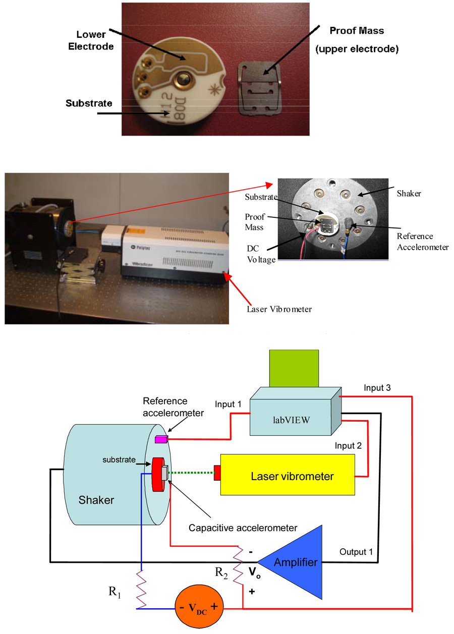
Two different samples of a commercial off-the-shelf capacitive accelerometer, fabricated by Sensata Technologies [15], are used for this investigation. We label them as sample a and sample b. The accelerometer, shown in figure 1a, is made up of an alloy 42 cantilever beam of thickness 150 microns with a proof mass (approximately of length =9mm and width= 5.32 mm) attached to its tip. The proof mass forms one side of the capacitive electrode used for detection. The separation between the stationary electrode and the proof mass is 50.8 microns. Despite its large dimensions compared to typical MEMS devices, this device serves the required purpose for the experimental investigation by providing all the essential characteristics of MEMS structures, such as electrostatic actuation and squeeze-film damping. Hence the results obtained from this device will shed light on the performance of smaller scale microstructures. The device was mounted on the head of a shaker and was electrically connected to a DC power supply. A laser vibrometer was used to monitor the time domain response of the accelerometer’s proof mass. A reference accelerometer was mounted on the head of the shaker to measure its acceleration. The LabView software was used to generate the required output signals and to read the input signals. Figures 1b and 1c show the experimental set up and data acquisition system.
Figure 1.
Figure 1a. A picture for a taken-apart commercial-off-the-shelf capacitive accelerometer, fabricated by Sensata Technologies [15], used for testing the shock-threshold switch.
Figure 1b. A picture for the experimental set up used for testing.
Figure 1c. Schematic for the experimental setup and the data acquisition system.
2.1 Response to DC electrostatic load
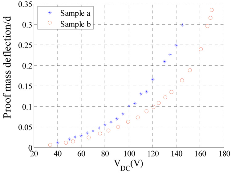
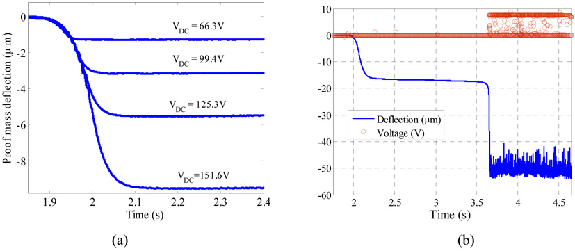
A Laser vibrometer was used to monitor the transient response of the proof mass when actuated by a DC voltage load. To determine the onset of pull-in, a simple electric circuit was used, which consists of a current-limiting resistor and a small lamp that lights up when the proof mass hits the substrate indicating pull-in. As a double check, a small resistor (470 Ω) was added to monitor the induced voltage Vo across it and an A/D LabVIEW input channel was used to read this voltage (see figure 1c). If the measured voltage Vo is greater than zero, then this indicates pull- in. The pull in voltages were found to be approximately 169.7 V for sample a and 145.0 V for sample b. Figure 2 shows the measured deflection of the accelerometer’s proof mass as a function of VDC for both samples. Figure 3 shows the transient behaviors of the proof mass of sample a below and at the pull-in voltage.
Figure 2.
Variation of the absolute value of the proof mass displacement normalized by the gap spacing underneath the proof mass d for various values of the DC bias VDC.
Figure 3.
The transient response of the proof mass of sample a for different voltage values below pull-in (a) and at the pull-in voltage VDC =169.7 V (b) as monitored by a Laser Doppler Vibrometer (blue). Figure b also shows the reading of the induced voltage across the 470 Ω resistor (red).
2.2 Response to shock load
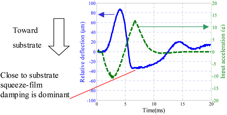
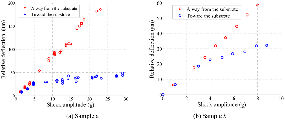
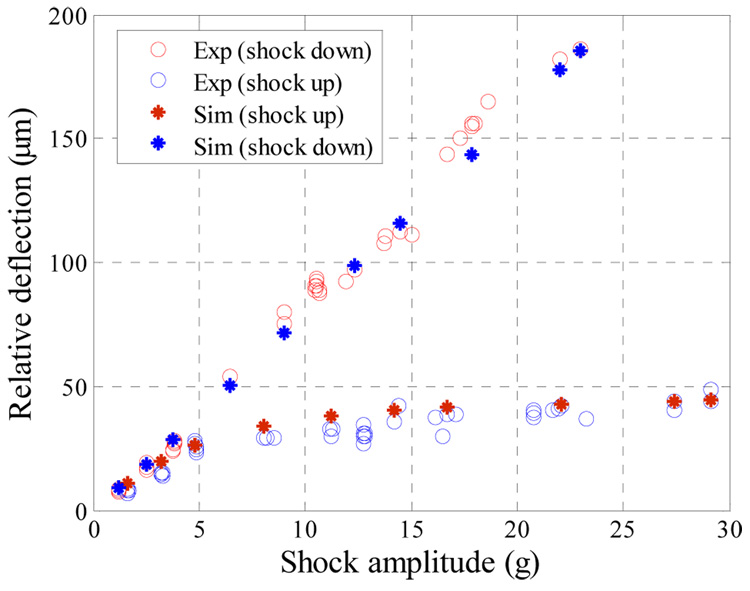
Two displacement measurements were obtained, one for the absolute motion of the proof mass and the other for the substrate motion, which is the same as that of the shaker head. By subtracting these two measurements, the displacement of the proof mass relative to the substrate was obtained. Figure 4 shows the transient response of the proof mass of sample a to a sine shock load of magnitude 13.0 g and duration T=5.0 ms, which is close to the natural period of the proof mass 5.3 ms. It can be seen that the response is asymmetric due to the effect of squeeze-film damping, which becomes more significant when the proof mass moves down toward the substrate. This asymmetric response is illustrated further in figure 5, which shows the measured relative deflection of sample a and b versus the shock amplitudes. The figure shows the deflection of the proof mass in both directions, toward the substrate and away from the substrate. For small values of mechanical shock, both deflection curves (toward and away from the substrate) are on top of each other indicating that the damping mechanism in both directions affects the proof mass linearly. However, as the value of the shock amplitude increases, both curves deviate from each other significantly. This is because of the increasing effect of the nonlinear squeeze film damping that becomes dominant as the proof mass approaches the substrate.
Figure 4.
The transient response of the proof mass of sample a when subjected to a mechanical shock alone as monitored through a Laser Doppler Vibrometer.
Figure 5.
The maximum deflection of the proof mass at different shock levels for the cases when the proof mass moves toward and away from the substrate.
2.3 Combined effect of shock and electrostatic forces (shock-threshold switch)
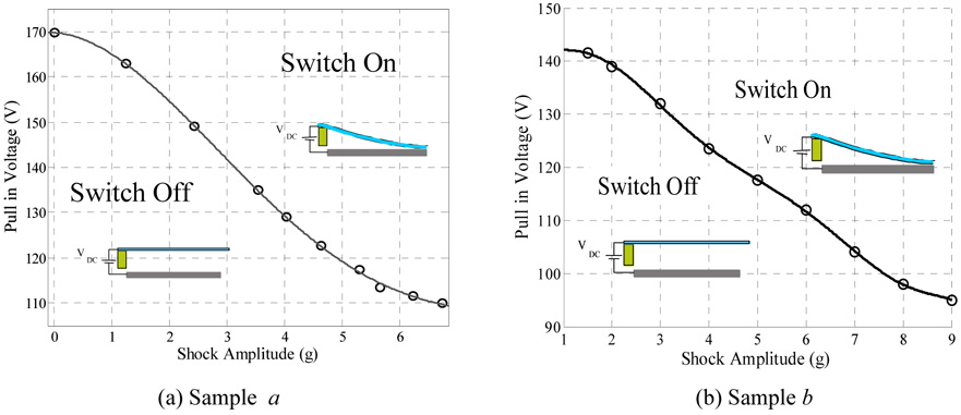
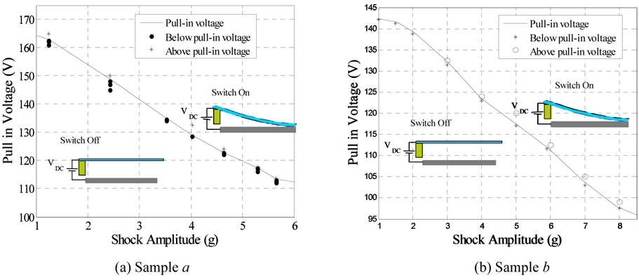
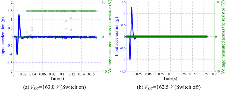
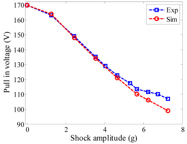
Next, the proof mass was excited by both electrostatic force and mechanical shock. This causes early pull-in instability below the static pull-in thresholds [1]. Figures 6a and b show the pull in voltage versus the shock amplitude for samples a and b, respectively. As seen from the figures, the pull in voltage dropped from 169.7 V at 0.0 g to 110.0 V at shock amplitude of 6.75 g for sample a. Also, the pull-in voltage dropped from 142.3 V at shock amplitude 1.0 g to 95.0 V at 9.0 g for sample b. These results agree with the reported theoretical results in [1]. The basic idea of the new switch can be understood by observing figure 6. One can tune the desirable threshold of actuation for the switch by adjusting the DC bias. If the acceleration exceeds the threshold value, the microbeam snaps down to close an electric circuit as a switch (ON state); otherwise the switch will remain open (OFF state). The robustness and reliability of the new switch was tested by altering the DC voltages to be slightly below or above the pull-in threshold of figures 6a and b for various values of pulse amplitude. As seen in figure 7, the switch shows excellent robustness and high sensitivity against variations in DC bias and shock level for the two samples. For example, figure 8 shows the input acceleration of 1.2 g magnitude with the voltage measured across the 470 Ω resistor. The results are shown for sample a, when VDC =163.0 V and VDC =162.5 V. The figure indicates that the switch exhibits pull-in only when VDC =163.0 V. Table 1 shows the sensitivity data for selected points in Fig. 7b.
Figure 6.
Pull in voltage of the accelerometer against the shock amplitude of a sine pulse of duration T = 5.0 ms.
Figure 7.
The switch sensitivity to variation in VDC. Points below the solid line represent the switch in the off-position while points on or above the solid line represent the switch in the on-position.
Figure 8.
Input acceleration of 1.2 g magnitude, with the voltage measured across the 470 Ω resistor.
Table 1.
Sensitivity of the switch for selected points on Fig.7b
| Shock value (g) | Pull in voltage (V) | Voltage below pull-in (switch off) (V) | Voltage beyond pull in (switch on) (V) |
|---|---|---|---|
| 3 | 132 | 131.5 | 132.5 |
| 4 | 123.5 | 123 | 124 |
| 5 | 117.5 | 117 | 120 |
| 6 | 112 | 111.7 | 112.5 |
| 7 | 104 | 103 | 105 |
3 Modeling, simulation, and comparison with experiments
In this section, a model for the response of the capacitive accelerometer under shock is developed and simulation results are presented. The model is used here to analyze the above-obtained experimental data and also to investigate methods to enhance the switch performance. The parameters of the simulation model are extracted experimentally for sample a only since sample b was damaged during the shock testing before extracting its parameters.
3.1 A single-degree-of-freedom model
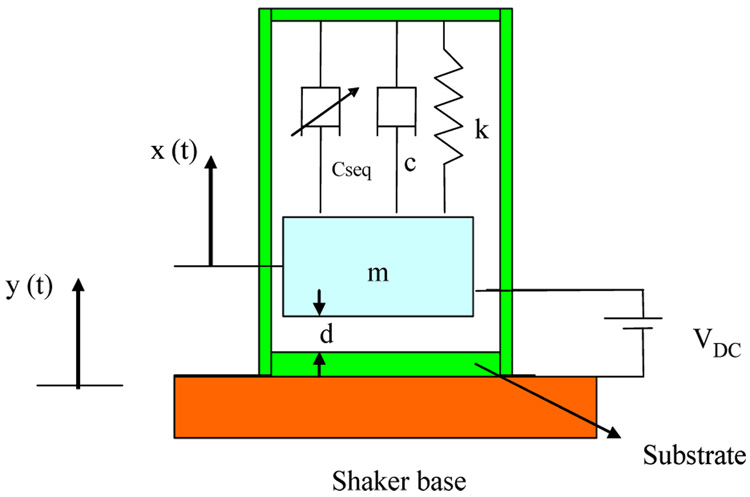
A single-degree-of-freedom model depicted in figure 9 is utilized to simulate the capacitive accelerometer under the effect of the electrostatic force and when subjected to a base excitation shock forcing. The proof mass of the device has a mass m, which forms one side of a variable capacitor. The equation of motion governing the behavior of the proof mass can be written as
| (1) |
where z is the relative deflection of the proof mass, which is the absolute motion of the proof mass x minus that of the substrate y (z=x−y), the superscript dot denotes time derivative, VDC is the DC polarization voltage, A is the electrode area assuming a complete overlapping between the two electrodes of the capacitor, d is the capacitor gap width, and ε is the dielectric constant of the gap medium. The parameter Fo denotes the shock amplitude and ÿ denotes the base acceleration, which is provided to the denotes device in the form of a shock pulse of duration T. The shape of the shock pulse can be assumed to be a half-sine or a full-sine pulse. The half and the full sine pulses are typical shapes used to represent shock forces [16]. They are expressed mathematically as
| (2) |
| (3) |
where, u(t) is the unite step function and T for the case of full-sine pulse represents half of the pulse duration. The shock input pulse ÿ can be also imported directly to the equation from the experimental test. This method will be used in the simulations in the cases when the generated shock pulse is slightly distorted from the typical shape of a half-sine and a full-sine pulse. It is worth noting that because of the negative sign associated with the input pulse ÿ in the right-hand side of equation (1), a positive shock acceleration pulse results in a negative relative deflection z for the proof mass (i.e. the proof mass moves toward the substrate in response to a positive acceleration pulse).
Figure 9.
A single-degree-of-freedom model for the capacitive accelerometer.
The parameter fseq denotes a dissipation force due to squeeze-film effect [17–20] and c is a constant viscous damping coefficient used to model the energy dissipation from sources other than those accounted for in the used squeeze-film damping model. Those include energy losses to the mounting and beam supports and those from the motion of the air through the slits and trenches surrounding the proof mass (see figure 1). To model the squeeze film effects, we use the Blech model [19], which analytically solves the linearized Reynolds equation with trivial pressure boundary conditions. The model will be modified to make the gap space varies with the proof mass motion. Therefore, fseq is expressed as
| (4) |
where , and σ is the squeeze number where pa is the ambient pressure, ω is the excitation frequency (since the structure here undergoes transient motion, ω will be taken as the natural frequency of the structure), i and n are odd indices of the series, η is the effective air viscosity coefficient, and σ is the squeeze number. It turns out in the studied case that using one term in the above series yields adequate accuracy and convergence. Because the value of σ is very small for the capacitive accelerometer studied here, the fluid can be considered as incompressible, and hence, the stiffening effect of squeeze-film damping is negligible.
There are some limitations that are worth noting in the used model for squeeze-film damping. First the cantilever beam and its poof mass undergo transient motion and large deflection due to shock. Hence, the linearized Reynolds equation, which is the base of the Blech model [19], may not capture accurately the fluid behavior. Also, the Blech model [19] was derived for a rigid plate that is open from all edges. In the studied case, the proof mass is attached to a flexible cantilever beam. The proof mass has three edges surrounded by air slits and one edge that is closed to the air flux.
3.2 Parameter extractions
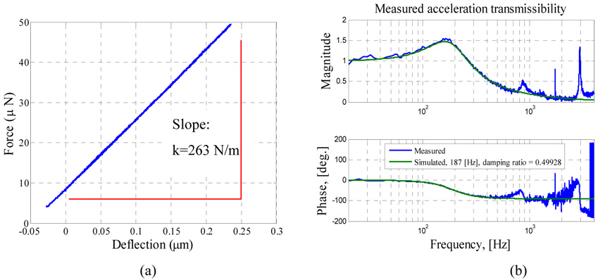
Several experiments were conducted to estimate the system’s parameters in equation (1). A nano-indenter machine was used to measure the deflection of the proof mass due to an applied mechanical load, from which the stiffness of the cantilever beam was found to be 263 N/m, (see figure 10a). The vibration response of the device was measured to identify the equivalent dynamic parameters when the bias voltage is zero and the nominal gap is maximum. A continuous random signal was used to drive the shaker. Then, using a curve fitting technique [21], it was found that the accelerometer’s fundamental natural frequency is near 187 Hz with an estimated linear damping ratio around ξ= 0.5, see figure 10b. This value of the damping ratio was used to calculate the constant damping coefficient c in equation (1). As indicated in Section 2.1, the gap space separating the proof mass from the substrate was found to be approximately 50.8 µm, and the pull in voltage to be 169.7 V (see figure 3b).
Figure 10.
Parameter extractions. (a) Force versus deflection curve used to extract the linear stiffness of sample a using the nano-indentation machine. (b) Frequency response of the capacitive accelerometer showing the extracted parameters (damping and natural frequency).
3.3 Model validation
The capability of the model of Section 3.1 to capture the transient behavior of the proof mass is investigated through comparing its results with the experimental data. First, we compare the response of the proof mass to mechanical shock alone, similar to the case of figure 5. Figure 11 compares the simulation (stars) and experimental data (circles) of the proof mass deflection of sample a for various values of shock amplitudes. Figure 11 shows good agreement between the simulation results and experimental data.
Figure 11.
Simulation results (stars) and experimental data (circles) of the proof mass deflection of sample a versus shock amplitude when T = 5.0ms.
In figure 12, the simulated results are compared with the experimental data when combining both the electrostatic and shock forces. The figure shows the simulation (circles) and experimental (square) results of the pull in voltage against the shock amplitude for a full sine pulse of duration T =5.0 ms. Figure 12 indicates good agreement between the simulation and experimental results for a wide range of shock amplitude. At high shock values however, the simulation results start to deviate slightly from the experimental data. This deviation can be attributed to the fact that the stiffness of the structure may have been changed during the repeated testing and impacting of the part by the large shock loads. Further, it was reported in [1] that the used model does not perform accurately when the shock force dominates the electrostatic force. This issue with the current model needs further investigation in the future.
Figure 12.
Simulation results (circles) and experimental data (square) for the pull in voltage of sample a against the shock amplitude of a sine pulse of T = 5.0ms.
3.4 The effect of damping when the pulse duration and shape are varied
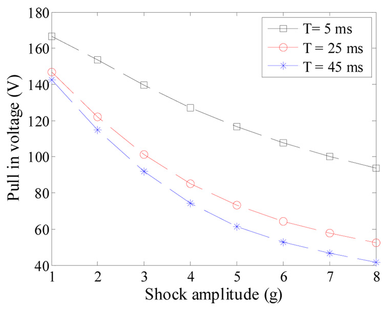
Next, the effect of the pulse duration on the switch performance is investigated. Figure 13 shows simulation results for the pull-in voltage of sample a against the shock amplitude of a full-sine pulse for three shock durations, T= 5.0 ms, 25.0 ms, and 45.0 ms. Surprisingly, the cantilever beam reaches pull-in due to a shock pulse of T = 25.0 and 45.0 ms at lower thresholds than that of T= 5.0 ms. Note that the beam experiences the shock force as a quasi-static load in the cases of T = 25.0 and 45.0 ms and as a dynamic load when T= 5.0 ms. Therefore, according to equation (1) and equation (4), the proof mass is not affected by squeeze-film damping and by damping in general when it is excited quasi-statically (the velocity term ż becomes negligibly small). On the other hand, damping becomes a major factor when the structure is excited dynamically.
Figure 13.
Simulation results for the pull-in voltage of the capacitive accelerometer against the shock amplitude of full-sine pulses of T= 5.0, 25.0, and 45.0 ms.
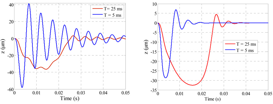
This is further illustrated in figure 14, which compares the time response of the proof mass when squeeze film damping effect is neglected and only light damping with damping ratio ξ=.05 is assumed (figure 14a) to the case when squeeze- film damping is not neglected. Results are shown for half-sine pulses of amplitude 5.0 g and duration T = 5.0 ms and 25.0 ms. The two figures indicate that in the case of the shock pulse of T =5.0 ms, the maximum response of the proof mass drops from 58.1 µm to 26.45 µm, while it decreases slightly from 36.5 µm to 32.2 µm in the case of T = 25.0 ms.
Figure 14.
A time history for the response of the capacitive accelerometer when actuated by a half-sine pulse amplitude of 5.0 g for the case of (a) no squeeze film damping (b) including the squeeze film damping effect. The figure shows that the quasi-static shock load (T=25.0 ms) effects the proof mass deflection more than the dynamic shock load (T=5.0 ms), in the presence of squeeze film damping.
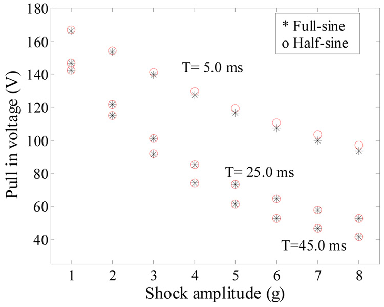
Figure 15 compares the pull in voltage of the accelerometer when excited by half-sine (circles) and full-sine (stars) shock pulses of various durations. Note from the figure that the shock shape has no effect on the shock-pull in curve when T =25.0 and 45.0 ms (quasi-static response) and it has some effect when T = 5.0 ms. It is concluded from figure 13–figure 16 that designing the new threshold switch to respond quasi-statically to shock load improves its sensitivity to shock load by lowering the required voltage of activation. Also it makes the switch less sensitive to variations in the shock duration and shock profile. The latter characteristic means more reliable and robust switch. This can be promising to lower the cost of packaging for these switches since they can operate in atmospheric pressure with no hermetic sealing or costly package required.
Figure 15.
Simulation results of the pull-in voltage of the capacitive accelerometer against the shock amplitude of half-sine and full-sine pulses of duration T= 5.0, 25.0, and 45.0 ms.
Figure 16.
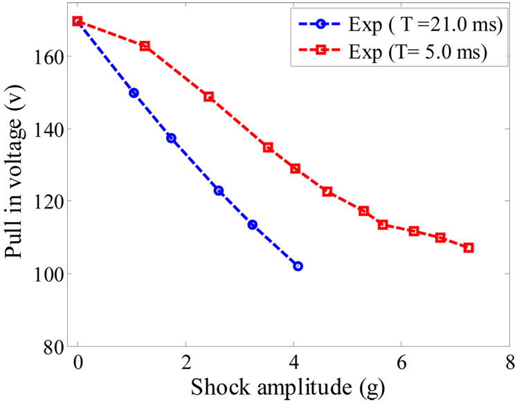
Experimental data of the pull in-shock curves when T = 5.0 ms and 21.0 ms.
4 Experimentally obtained shock-pull-in curves for quasi-static and dynamic loads
As discussed in the previous section, designing the new threshold switch to response quasi-statically to a shock load lowers its activation threshold when operating in ambient pressure and makes it insensitive to damping and shock conditions. Next, we investigate the validity of this conclusion experimentally. Figure 16 shows experimental data for the pull-in-shock curve for sample a. In this experiment full- sine shock loads were applied of durations T = 5.0 ms and 21.0 ms. The figure indicates that a higher voltage load is required to cause pull- in for the case of shock duration T = 5.0 ms (dynamics shock load) compared to the shock duration of T =21.0 ms (quasi-static load). This agrees with the simulation results of Section 3.3.
5 Summary and conclusion
We presented experimental and theoretical investigation to the characteristics and performance of a new class of tunable threshold-acceleration switches actuated at or beyond a specific level of mechanical shock or acceleration. We tested two commercial off-the-shelf capacitive accelerometers operating in air under mechanical shock and DC loading. A single-degree-of-freedom model was used to simulate the dynamic behavior of the device. The model accounts for the squeeze-film effect, electrostatic loading, and mechanical shock. Good agreement between the simulation results and the experimental for the switch response was obtained. Nevertheless, we believe there is still room for improvement on the used model in modeling the transient behavior of the microstructure under squeeze-film damping. Also improvement is needed to model electrostatically actuated microstructures in shock-dominated regimes. Our results indicate that designing these new switches to respond quasi-statically to mechanical shock make them robust against variations in shock shape and duration. More important, this makes the switches insensitive to variation in damping conditions. This can be promising to lower the cost of packaging for these switches since they can operate in atmospheric pressure with no hermit sealing or costly package required.
Acknowledgment
The authors would like to thank Mr. Andrew Willner and Sensata Technologies for providing the parts used for testing, Prof. Jungyan Cho for his help with the Nano-indentation machine, and Mr. Bill Buttler for his help in the experimental setup.
References
- 1.Younis MI, Miles R, Jordy D. Investigation of the response of microstructures under the combined effect of mechanical shock and electrostatic forces. J. Micromech. Microeng. 2006;16:2463–2474. doi: 10.1088/0960-1317/16/11/03. [DOI] [PMC free article] [PubMed] [Google Scholar]
- 2.Chang, Jsung-Hsi Shock absorber United States Application 20050155849, freepatentsonline. 2003 [Google Scholar]
- 3.Frobenius WD, Zeitman SA, White MH, O'Sullivan DD, Hamel, Wolf RG. Microminiature ganged threshold accelerometers compatible with integrated circuit technology. Proc IEEE Electron Devices. 1972;vol 19:37–40. [Google Scholar]
- 4.Robinson C, Overman D, Warner R, Blomqulst T. Problem encountered In The development of the microscale G-switch using three design approaches. Proc. Int. Conf. on Solid-State Sensors and Actuators; Tokyo, Japan. 1987. pp. 410–413. [Google Scholar]
- 5.Loke Y, McKinnon GH. fabrication and characterization of silicon micromachined threshold accelerometer. Sensors and Actuators A. 1991;29:235–240. [Google Scholar]
- 6.Man PF, Mastrangelo CH. Surface micromachined shock sensor for impact detection. Proc. Solid-State Sensor and Actuator Work shop; Hilton Head, South Carolina. 1994. pp. 156–159. [Google Scholar]
- 7.Go JS, Cho Y, Kwak BM, Kwanhum P. Snapping microswitch with adjustable Acceleration threshold. Sensors and Actuators. 1996;45:579–583. [Google Scholar]
- 8.Selvakumar A, Yazdi N, Najafi K. A Wide-Range Micromachined threshold accelerometer array and interface circuit. J. Micromech. Microeng. 2001;11:118–125. [Google Scholar]
- 9.Noetzel J, Tonnesen T, Beneck W, Binder J, Mader G. Quasianalogy accelerometer using microswitch array. Sensor and Actuators A. 1996;54:574–578. [Google Scholar]
- 10.Sun X, Zhou S, Carr WNA. surface micromachined latching accelerometer. Proc. Int. Conf. on solid-state sensors and actuator; Chicago. 1997. pp. 1189–1192. [Google Scholar]
- 11.Tonnesen T, Ludtke O, Noetzel J, Binder J, Mader G. Simulation, design and fabrication of electroplated acceleration switches. J. Micromech. Microeng. 1997;7:237–239. [Google Scholar]
- 12.Wycisk M, Tonnesen T, Binder J, Michaelis S, Timme HJ. Low-cost post-COMS integration of electroplated microstructure for inertial sensing. Sensor and Actuators A. 2000;83:93–100. [Google Scholar]
- 13.Matsunaga T, Esashi M. Acceleration switch with extended holding time using squeeze film effect for side airbag system. Sensors and Actuators A. 2002;100:10–17. [Google Scholar]
- 14.McNamara S, Gianchandani YB. LIGA fabrication 19-element threshold accelerometer array. Sensor and Actuators A. 2004;112:175–183. [Google Scholar]
- 15. www.sensata.com.
- 16.Lang GF. Shock’s on shakers. J. Sound and Vibration. 2003;37:12–20. [Google Scholar]
- 17.Starr JB. Squeeze film damping in solid state accelerometer. Proc. IEEE Solid State Sensor and Actuator Workshop; Hilton Head Island SC. 1990. pp. 44–47. [Google Scholar]
- 18.Nayfeh AH, Younis MI. A New Approach to the Modeling and Simulation of Flexible Microstructures under the Effect of Squeeze-Film Damping. J. Micromech. Microeng. 2004;14:170–181. [Google Scholar]
- 19.Blech JJ. On isothermal squeeze films. Journal of Lubricants Technology. 1983;105:615–620. [Google Scholar]
- 20.Sudipto KD, Aluru NR. Coupling of hierarchical fluid models with electrostatic and mechanical models for the dynamic analysis of MEMS. J. Micromech. Microeng. 2006;16:1705–1719. [Google Scholar]
- 21.SU Q. PhD Thesis. State University of New York at Binghamton mechanical Engineering Department; 2005. Measurement and characterization of miniature silicon microphone diaphragm. [Google Scholar]


