

Abstract
The molecular motor protein myosin VI moves toward the minus-end of actin filaments with a step size of 30–36 nm. Such large step size either drastically limits the degree of complex formation between dimer subunits to leave enough length for the lever arms, or requires an extension of the lever arms' crystallographically observed structure. Recent experimental work proposed that myosin VI dimerization triggers the unfolding of the protein's proximal tail domain which could drive the needed lever-arm extension. Here, we demonstrate through steered molecular dynamics simulation the feasibility of sufficient extension arising from turning a three-helix bundle into a long α-helix. A key role is played by the known calmodulin binding that facilitates the extension by altering the strain path in myosin VI. Sequence analysis of the proximal tail domain suggests that further calmodulin binding sites open up when the domain's three-helix bundle is unfolded and that subsequent calmodulin binding stabilizes the extended lever arms.
Introduction
Myosin is a superfamily of motor proteins found in all eukaryotic cells (1). It converts chemical energy from ATP hydrolysis to mechanical work that powers muscle contraction and directional movement along actin filaments (1–3). The actin-myosin catalytic cycle, according to the so-called swinging lever-arm hypothesis (2), starts with ATP hydrolysis within the myosin motor domain in the absence of actin. Subsequent interactions with actin filaments release Pi and MgADP (1,4) and induce conformational change in the myosin motor domain (5–7). The conformational change within the motor domain is amplified through a structural component called the converter subdomain (8,9), leading to movement, also known as the powerstroke, of the so-called lever arm—the latter forming an extended single α-helix containing calmodulin (CaM) and CaM-like light-chain binding sites. The magnitude of the powerstroke, or step size in the case of the processive motor protein, is determined by the length of the lever arm.
A unique member of the myosin superfamily is myosin VI (2,3,10,11) as shown in Fig. 1. Myosin VI is associated with several functions ranging from transport of vesicles during endocytosis (12), maintenance of structure and function of the Golgi complex (13), and hair cell mechanics in hearing (14). Intriguingly, whereas myosin VI isolated from cells is found in a stable monomeric conformation (15), dimerization of myosin VI is observed upon either monomer clustering (16) or binding of cargo (17,18). Unlike other myosin motors that “walk” toward the plus- (or barbed) end of actin filaments, myosin VI moves in the opposite direction (i.e., toward the minus-end of actin filaments) (19–21). As shown in Fig. 1, myosin VI contains an actin filament-binding motor domain at the N-terminus that includes the ATP binding site, a unique insert-2 domain that associates with a calmodulin (CaM); an IQ motif that binds Ca2+-depleted calmodulin (apo-CaM); a proximal tail (PT) domain that forms a three-helix bundle as seen crystallographically (22); an α-helical (23) medial tail (MT) domain; a distal tail (DT) domain; and a cargo binding domain (CBD) (17).
Figure 1.
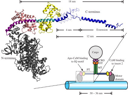
Structure of myosin VI. (Lower right) Schematic of the myosin VI dimer moving on an F-actin filament (light blue). Myosin VI consists of an N-terminal motor domain (gray) followed by insert-2 and IQ motifs, which bind calmodulin (CaM; pink) and apo-CaM (yellow), respectively, and are occluded in the schematic. The IQ motif is followed by the proximal tail (PT) domain (blue), medial tail (MT) domain (green), and distal tail (DT) domain (orange). The C-terminal cargo binding domain (CBD; purple) associates with the cargo. (Upper left) Expanded view of a portion of myosin VI in cartoon representation with the same color scheme as in the lower-right schematic. Insert-2 (purple) and IQ motif (cyan) are shown explicitly. The model shown was built by fusing two x-ray structures (PDB codes: 2BKI (21) and 3GN4 (22)). The PT domain (blue) is shown in its extended form, i.e., with its three α-helices extended to a full length of 12 nm, being capable then together with the dimer partner of a 30–36-nm step size (see text) (22). The PT domain is also shown in its unextended, 4-nm-long, three-helix zig-zag bundle form (22) in thin tube representation (see also Fig. 3D). The extended conformation of the PT domain shown is a key result from this study (see Results).
There are two unique class-specific structural elements in myosin VI, namely insert-1 and insert-2. The insert-1 element is located near the nucleotide pocket within the motor domain, and permits gating between the two heads by impeding ATP binding (24,25). The insert-2 element, found between the motor domain and the lever arm, is responsible for the reversal in the direction of myosin VI movement. Myosin VI is also known to take a large step size despite its short lever arm containing only two CaM binding sites; the step size cannot be easily explained by the lever-arm hypothesis (2,22,26,27).
This study asks how myosin VI dimers realize their observed step size of 30–36 nm (20,26,28–30). Two models (22,31), compared in Fig. 2, suggest how the myosin VI structure permits a 30–36-nm step size. The models make contrary assumptions about the effective extension of myosin VI's proximal tail domain. As suggested in Fig. 1, the domains may either form a short (4-nm) three α-helix zig-zag bundle, or (as investigated in the following) extend out to a 12-nm length. In the transition, starting from the zig-zag bundle, the three α-helices move past each other, extending from a 4-nm-long geometry to a geometry of tripled length. In this zig-zag extension model, the MT domains of the myosin VI dimer form a tight complex and, hence, cannot contribute to the step size (Fig. 2 A); in the other model where the three α-helices together span only 4 nm in length, the MT domains remain separated and, hence, contribute to the step size (Fig. 2 B).
Figure 2.
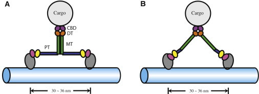
Alternative geometries suggested for myosin VI stepping. (A) A model proposed in Mukherjea et al. (22) and Kim et al. (32) and investigated in this study, which assumes dimerized medial tail (MT) domains (green) and extended proximal tail (PT) domains (blue). (B) A model proposed in Spink et al. (31), which assumes dissociated MT domains and short PT domains (see Fig. 1). Distal tail (DT) domain (orange) and cargo binding domain (CBD; purple) remain the same in the alternative models.
The suggested stepping geometries shown in Fig. 2 differ in two respects: complex formation or not between the MT domains; and zig-zag extension or not of the three-helix bundle PT domain. Mukherjea et al. (22) have shown that
-
1.
Myosin VI constructs with the distal-tail and cargo-binding domains truncated dimerize and step processively, suggesting that dimerization can occur below the distal-tail domain.
-
2.
Fluorescence quenching with two TMR fluorophores labeled at T845 (in helix I) and A880 (in helix II) demonstrates that the PT domain transforms from a compact to an extended conformation.
-
3.
Deletion of the last two helices of the PT domain greatly reduces the step size of myosin VI.
A combined experimental and computational study demonstrated that the MT domain of myosin VI is capable of dimerization through electrostatic interactions (32). This study together with Mukherjea et al. (22) supports the myosin VI dimer model shown in Fig. 1 and Fig. 2 A. Here, we extend the recent study in Kim et al. (32) and test the feasibility of three-helix bundle PT domain extension.
Simulations presented below and summarized in Table 1 demonstrate that the three-helix bundle, indeed, can be extended readily without disruption of its α-helical secondary structure. The simulations suggest, furthermore, that CaM binding plays a crucial role in inducing as well as mechanically stabilizing the extended conformation of the PT domain.
Table 1.
Summary of simulations
| Name | Structure | Type | Ensemble | Atoms | Size (Å3) | Time (ns) |
|---|---|---|---|---|---|---|
| PIC-eq | PT, IQ, CaM | EQ | NPT/NVT | 74,421 | 94 × 92 × 90 | 34 |
| PIC-sr-1 | PT, IQ, CaM | SMD/RE | NV/NVT | 104,662 | 206 × 70 × 72 | 80 |
| PIC-re-1∗ | PT, IQ, CaM | RE | NVT | 104,662 | 206 × 70 × 72 | 120 |
| PIC-sr-2∗ | PT, IQ, CaM | SMD/RE | NV/NVT | 104,662 | 206 × 70 × 72 | 20 |
| PIC-re-2† | PT, IQ, CaM | RE | NVT | 104,662 | 206 × 70 × 72 | 100 |
| P-sr | PT | SMD/RE | NV/NVT | 83,840 | 180 × 70 × 70 | 100 |
| P-re‡ | PT | RE | NVT | 83,840 | 180 × 70 × 70 | 100 |
Under the column “Type,” the term “EQ” denotes an equilibrium molecular dynamics simulation, “SMD” denotes constant velocity (2 Å/ns) steered molecular dynamics simulations, and “RE” denotes relaxation simulations. The “Ensemble” column lists the variables held constant during the simulations; “N”, “V”, “P”, and “T” correspond to number of atoms, volume, pressure, and temperature, respectively. Movie S1, Movie S2, and Movie S3 depicting the simulations are provided in the Supporting Material.
Started from the end of simulation PIC-sr-1.
Started from the end of simulation PIC-sr-2.
Started from the end of simulation P-sr.
Methods
Simulated systems
Two molecular systems were prepared for the simulations listed in Table 1. The first system included the myosin VI PT domain (residues 834–913), as well as the IQ motif (residues 811–833) with a bound apo-CaM. Atomic coordinates of these structures were obtained from the Protein Data Bank (PDB code 3GN4) (22). The unresolved region in the crystallographic structure (residues 850–863) was modeled as a loop as suggested in Mukherjea et al. (22); missing hydrogen atoms were generated using the psfgen plugin in VMD (33) with the CHARMM27 topology file (34). The PT-IQ-CaM structure was then placed in a water box of dimension 94 Å × 92 Å × 90 Å with 23,475 TIP3P (35) water molecules, and neutralized at 50 mM KCl. The solvated and neutralized PT-IQ-CaM system contained altogether 74,421 atoms and was subjected to 34 ns of equilibrium molecular dynamics. To accommodate the molecular extension encountered in stretching simulations, the equilibrated PT-IQ-CaM system was placed in a larger water box of dimension 206 Å × 70 Å × 72 Å, and similarly neutralized at 50 mM KCl. This larger system contained 104,662 atoms.
In the second molecular system, only the myosin VI PT domain was included to assess the effect of deleting the IQ motif and the CaM molecule. The structure of the PT domain was taken from the equilibrated PT-IQ-CaM structure, as discussed above, with the IQ and CaM regions truncated. The PT domain was also solvated and neutralized; the final system contained 83,840 atoms.
Molecular dynamics protocols
All molecular dynamics simulations were performed with a development version of NAMD 2.7b2 (36) using the CHARMM27 force field with CMAP correction (34,37,38). The equilibrium molecular dynamics simulation (PIC-eq in Table 1) was conducted in the NPT ensemble for the first 4 ns. Once the system in the NPT ensemble was fully equilibrated to the desired pressure of 1 atm, the NVT ensemble was applied for 30 ns, with the volume reached in the prior NPT ensemble resulting in a pressure fluctuating slightly at ∼1 atm. Constant temperature at 310 K was maintained using Langevin dynamics with a damping constant of 1 ps−1; constant pressure of 1 atm was maintained using a Nosé-Hoover Langevin piston barostat (36) with a period of 200 fs and a decay rate of 100 fs; isotropic cell scaling was used; the long-range electrostatic force was computed using the particle-mesh Ewald summation method with a grid size of <1 Å; the multiple timestepping algorithm (39,40) was employed, with an integration timestep of 2 fs, the short-range force being evaluated every timestep, and the long-range electrostatics every second timestep. Protein bonds involving hydrogens were constrained using the RATTLE algorithm (41); the water geometry was maintained using SETTLE (42).
Steered molecular dynamics (SMD) simulations (43) (denoted by “SMD” under the column “Type” in Table 1) were carried out by harmonically restraining the N-terminal Cα atom, while an external force was applied to the C-terminal Cα atom at a constant velocity of 2 Å/ns to unfold the PT domain. An integration timestep of 1 fs was adopted, with a multiple timestepping algorithm (39,40) employed to compute interactions between covalent bonds every timestep, the short-range nonbonded interactions every other timestep, and the long-range electrostatic forces every fourth timestep (so-called 1-2-4 timestepping). The multiple timestepping algorithm accelerates sampling of hundreds of nanoseconds in the simulation, achieving a balance between computational efficiency and accuracy without distorting the dynamic behavior of the simulated systems (44,45).
Each 10 ns of SMD simulation was followed by 10 ns relaxation to give the molecular systems a chance to relax from forced stretching (46). Relaxation simulations (denoted by “RE” under the column “Type” in Table 1) were performed with the same procedure as the equilibrium simulation described above, except with the two terminal Cα atoms fixed. After sufficiently many cycles of 10-ns SMD/10-ns relaxation simulations (denoted by “SMD /RE” under the column “Type” in Table 1) were completed, i.e., until the PT domain unfolded, a final relaxation simulation (lasting either 100 ns or 120 ns) was performed with the two terminal Cα atoms harmonically restrained instead of being held fixed.
Results
Equilibrium dynamics of the PT domain
To characterize the equilibrium properties of the myosin VI PT domain, a 30-ns equilibrium MD simulation (simulation PIC-eq in Table 1) was performed as described in Methods. The simulated system included the IQ motif (residues 811–833), the CaM molecule bound to the IQ motif, and the PT domain (residues 834–913) (PDB code 3GN4 (22)). The system remained stable during the simulation, as demonstrated by monitoring the central carbon root-mean-square-deviation (Cα-RMSD) with respect to the initial structure. The Cα-RMSD of the simulated system approached a value of 3 Å after 20 ns (Fig. 3 A); the Cα-RMSD value of the IQ-bound apo-CaM, which is the most rigid component, assumed a value of ∼2 Å. The major contribution to the flexibility in the PT-IQ-CaM system, as measured by the Cα-RMSD values and shown in Fig. S1 in the Supporting Material, stems from the disordered loop (residues 850–863) between helix I and helix II of the PT domain. One can conclude from these Cα-RMSD values that the equilibrated structure of the PT domain, IQ motif, and apo-CaM system is sufficiently stable for further SMD studies.
Figure 3.
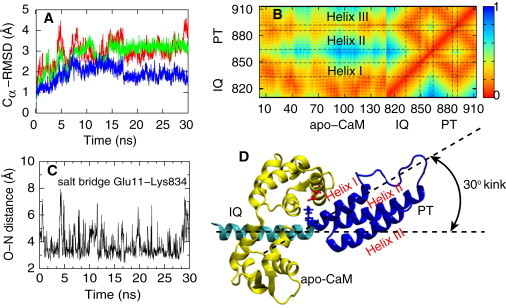
Results from the equilibrium simulation of myosin VI (simulation PIC-eq in Table 1).The simulated system includes the PT domain and the IQ motif with a bound apo-CaM. (A) Cα-RMSD values of the whole simulated system (red), of the PT domain (green), and of apo-CaM (blue). The simulated structures relaxed within 20 ns. (B) Contact map between residues (0, close; 1, far away). In addition to an expected close contact between apo-CaM and IQ motif, apo-CaM also contacts the PT domain, maintaining the kink (see text) between the IQ motif and the PT domain. (C) Salt bridge between Glu11 of the apo-CaM and Lys834 of the myosin VI, observed through the respective O–N distance. (D) Simulated system with IQ motif (cyan), apo-CaM (yellow), and PT domain (blue) showing a zig-zag geometry of the helix I-helix II-helix III system. The crystal structure (PDB 3GN4) was obtained from Mukherjea et al. (22). A 30° kink forms between IQ motif and PT domain.
Residue-residue contacts for the PT-IQ-CaM system were monitored over the equilibrium simulation and summarized in the contact map in Fig. 3 B. The CaM molecule is found closely associated with the IQ domain, as expected. Interestingly, the same CaM molecule also exhibited noticeable contact with the PT domain, most prominently with helix I. Indeed, during the 30-ns equilibrium MD simulation, significant hydrophobic interaction as well as several transient salt bridges were observed between the CaM and the PT domain. One particularly long-lasting salt bridge, not captured in the x-ray structure (22), was found between Glu11 from the CaM and Lys834 from the myosin VI (Fig. 3, C and D). This salt bridge is located near the junction between PT domain and IQ motif, where the α-helix forms a kink of ∼30° (Fig. 3 D). It is possible that the observed salt bridge between the CaM molecule and PT domain stabilizes this kink. The kink plays a crucial role in the extension of the PT domain as discussed below.
SMD simulations extending the PT domain
In Mukherjea et al. (22), unfolding of the PT domain was proposed to occur after dimerization of myosin VI. However, the crystal structure reported revealed a three-helix zig-zag bundle conformation of the PT domain which is too short to realize a 30–36-nm step size. To test the feasibility of PT domain extension as well as the structural stability of the resulting extended PT domain, steered molecular dynamics (SMD) simulations were employed as described in Methods. SMD simulation (43,45,47) is a proven tool for characterizing mechanical responses of proteins and ligands (43,48–57), including motor proteins myosin and kinesin (58–60). We note that dimerization of the MT domain can contribute >32 kcal/mol in free energy (32), which could be spent to extend the PT domain; the SMD method mimics the work exerted on the PT domain derived through MT domain dimerization.
The equilibrated structure of the PT-IQ-CaM system was placed in a water box large enough to accommodate the zig-zag extension process described in the Introduction. During the SMD simulation, the N-terminal Cα atom (residue Lys811) was harmonically restrained, while the C-terminal Cα atom (residue Leu913) (with position x(t) at time t) was pulled by means of a constraining force f = −k(x(t) − x0(t)) at a constant velocity along the x direction (as defined in Fig. 4), where x0 is the position of a dummy atom attached to a spring with force constant k. After each 10-ns SMD stretching, the system was permitted to relax for 10 ns, strictly fixing the extension e(t), defined as e(t) = x(t) − x(0), to the values e (10 ns), e (30 ns), e (50 ns), and e (70 ns) during time intervals 10–20 ns, 30–40 ns, 50–60 ns, and 70–80 ns, respectively. Fig. 4 (inset) shows the extension resulting from the procedure; one can note that e(t) assumes, in the stated time intervals, values close to x0(10 ns) = 2 nm, x0(30 ns) = 4 nm, x0(50 ns) = 6 nm, and x0(70 ns) = 8 nm, as expected. Subsequently, i.e., after 80 ns, the C-terminal Cα atom was restrained by a force f = −k(x(t) – x0) with x0 = 8 nm. For the spring constant k of the constraining force, we selected a value of 3 kBT0/Å2 (kB, Boltzmann constant; T0 = 300 K) which corresponds to a thermal RMSD deviation of ≈ 0.6 Å that is typical for SMD simulations (45,48,61).
Figure 4.
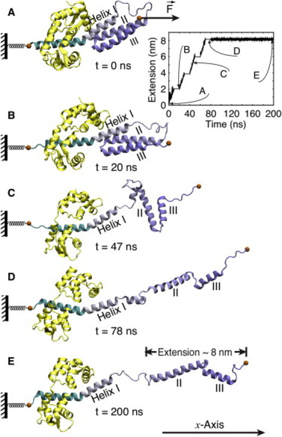
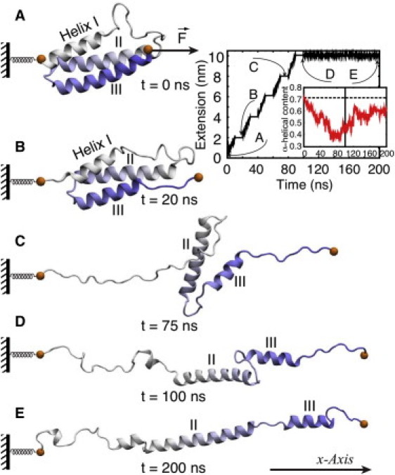
Stretching of myosin VI PT domain. Shown are snapshots during the force-induced extension process at (A) t = 0 ns; (B) t = 20 ns; (C) t = 47 ns; (D) t = 78 ns; and (E) t = 200 ns. Extension is found to proceed in two steps: a first step (A → B → C) involves dissociation of helices II and III from helix I; a second step (C → D) involves loss of contact between helix II and helix III. (Inset) Sequence of pulling and relaxation intervals during the 200-ns simulation (see text). The zig-zag extension process and the subsequent relaxation is shown in Movie S1 in the Supporting Material.
Two-step zig-zag extension
The three-helix PT domain was seen to extend in the SMD simulation from its initial zig-zag geometry in two distinct steps as shown in Fig. 4. Helix I dissociated within 50 ns from helices II and III (Fig. 4, A–C) which resulted in an intermediate conformation where helices II and III remained in contact, while helix I continued to interact with apo-CaM (the latter interaction was seen to last throughout the simulation). The disordered loop between helices I and II (residues 850–863) stretched out in response to the external force. Around 80 ns, helices II and III dissociated (Fig. 4 D), at which point the PT domain had its three α-helices aligned linearly and reached its extended conformation (Fig. 4 E).
The force-extension data of the stretching process are plotted in Fig. 5 A. One can recognize clearly a range of extension (0–5.5 nm) during which strong forces are needed to stretch the PT domain, followed by a range of extension (5.5–8 nm) where small forces suffice. The extension ranges correspond to step I (A → B → C) and step II (C → D) in Fig. 4. In particular, the force peak of ∼250 pN at ∼3–4-nm extension corresponds to the separation of helix I from helices II and III. The average force applied in the extension range 0–5.5 nm is 158 pN (Fig. 5 B; green squares). The average force in the extension range 5.5–8 nm, corresponding to the separation of helices II and III, is only 52 pN (Fig. 5 B; blue triangles). The adapted simulation protocol, namely having 10-ns relaxation simulation between SMD simulations, partially released the tension built-up during force stretching, resulting in abrupt decrease of force at extension 2 nm and extension 4 nm.
Figure 5.
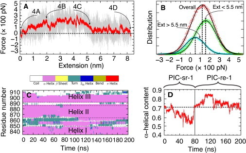
Characterization of PT domain extension. (A) Force-extension data from simulation PIC-sr-1. The force shown is measured through the expression f = −k(x(t) – x0(t)) and the extension through e(t) = x(t) − x(0). Force values were taken every 2 ps (gray trace); these force values are averaged over a gliding 200-ps window (red). Large forces arise when the PT domain becomes less compliant to the imposed moving constraint x0(t), i.e., when it does not follow the constraint readily, increasing the separation x0(t) − x(t). Labels 4A, 4B, 4C, and 4D correspond to the simulation snapshots in Fig. 4. The region of highest force, at ∼4 nm, corresponds to a free energy barrier characterizing the transition B → C in Fig. 4. (B) Force distribution at different steps of PT domain extension. The first step was sampled over extensions <5.5 nm (green) and the second step over extensions >5.5 nm (blue). Force distribution for the overall process is also shown (red). The distributions can be matched closely to Gaussians, yielding average forces of 158 pN (step 1), 52 pN (step 2), and 123 pN (overall). (C) Time evolution of PT domain secondary structure. The α-helices are seen to remain intact; only a small portion of helix III is lost. The analysis for this figure used the Timeline plugin of VMD (33). (D) Time evolution of α-helical content. Initially (t < 80 ns), a decrease of α-helical content arises that is regained quickly during the final, i.e., 120-ns long, relaxation simulation. The α-helical content exceeds the starting value (dotted line) due to the formation of some transient helical structure in the loop region between helices I and II (residues 851–863).
The stretching force arising in our simulation is higher than the ones arising in single-molecule pulling experiments. The discrepancy results from the faster stretching in the SMD simulation, which is dictated by lack of computer power. However, as long as the simulation pulls a system along the correct extension coordinate, the higher forces usually do not alter the extension mechanism (45,62–64). Even under physiological conditions the force generated in a single molecule can exceed 100 pN (65), but the stall force for a processive motor is typically on the order of only a few pN and 2 pN for myosin VI in particular (66). As pointed out above, the conformational change of myosin VI, such as PT domain extension, could be driven by MT domain dimerization, which can furnish work amounting to >32 kcal/mol (∼220 pN·nm) (32).
Structural stability of the extended PT domain
Four cycles of 10-ns SMD simulation and 10-ns relaxation simulation were sufficient to fully extend the PT domain (simulation PIC-sr-1 in Table 1), yielding a length of 12 nm. The structural stability of the extended configuration of the PT domain was probed in a further 120-ns relaxation simulation (simulation PIC-re-1 in Table 1; see also Figs. 4 and 5). During the 120-ns relaxation, the three PT domain α-helices retained largely their secondary structure as shown in Fig. 5 C. Indeed, the small fraction of α-helical structure near the C-terminus of the PT domain, disrupted during the SMD simulation, was recovered during the relaxation, and the total α-helical content in the unfolded PT domain increased to >70% (Fig. 5 D), a value which agrees well with circular-dichroism measurement (22). A transient short helical segment was seen to form in the loop between helices I and II (residues 851–863).
As discussed in Mukherjea et al. (22), the PT domain has to be fully extended, with α-helices intact, to accommodate a step size of 36 nm of the myosin VI dimer. As shown in Fig. 1, the contribution to the step size from each myosin VI monomer is ∼18 nm, with the PT domain accounting for 12 nm and other structural segments (CaM-bound insert-2 and IQ motif) accounting for 6 nm. Our simulation indeed extended the PT domain to 12 nm. To accommodate the large fluctuation in step size seen in experiment, an additional 10-ns SMD (and 10-ns relaxation) was performed to further extend the end-to-end distance of the PT domain to 14 nm (simulation PIC-sr-2 in Table 1); a subsequent relaxation of 100-ns duration was carried out for the further stretched-out PT domain (simulation PIC-re-2 in Table 1). The 14-nm extended PT domain was seen to retain its secondary structure during stretching and relaxation. The results are shown in Fig. S2. The trajectories showing simulation PIC-sr-2 and PIC-re-2 are displayed in Movie S2 in the Supporting Material.
Stretching a PT domain without IQ motif and CaM
The conducted simulations described included the IQ motif with a bound apo-CaM molecule, in addition to the PT domain. A separate simulation was performed that contained only the PT domain (simulation P-sr in Table 1), the simulation protocol being identical to the one in simulation PIC-sr-1. The moving constraint in this SMD simulation was applied to the C-terminal Cα atom (residue Leu913), while the N-terminal Cα atom (residue Lys834) was harmonically restrained to a fixed position. In simulation P-sr, the secondary structure of the three PT domain α-helices became quickly disrupted as demonstrated through a series of simulation snapshots shown in Fig. 6. Although the order of the dissociation of the helices remained the same as in simulation PIC-sr-1, namely, helix I detached from helices II and III, before the latter helices separated, it can be seen that, in simulation P-sr, helix I completely lost its secondary structure (Fig. 6, C–E, and Fig. S3). The α-helical content in the PT domain was reduced to 40% during P-sr, and was not fully regained in the subsequent 100-ns relaxation simulation P-re (Fig. 6, inset).
Figure 6.
Stretching of a PT domain without IQ motif and CaM. The presentation follows Fig. 4 and Fig. 5D. Shown are snapshots from simulations P-sr (0–100 ns) and simulation P-re (100–200 ns) at (A) t = 0 ns; (B) t = 20 ns; (C) t = 75 ns; (D) t = 100 ns; and (E) t = 200 ns. Helix I loses its α-helical structure. The α-helical structure of helix III is also partially lost. The 100–200-ns relaxation simulation did not recover the lost helical content. Simulations P-sr and P-re are shown in Movie S3.
In the case of simulation P-sr, the applied force acts at an average angle of 15° relative to the three α-helices of the PT domain. Addition of the IQ motif and the bound apo-CaM molecule alters this angle to an average value of 30°, as can be seen by comparing Figs. 4 and 6 (see also Fig. S4). The slight difference in the relative stretching direction implies that, in the former case, 26% (i.e., sin(15°)) of the applied force acts perpendicular to the helix axes whereas 50% (i.e., sin(30°)) acts in the latter case. Naturally, force applied to the PT-IQ-CaM system separates the helices more readily, making extension easier. Conversely, with more of the applied force (96.6%, i.e., cos(15°)) acting along the helix axes, in the case of the PT domain-only simulation, helices are stretched more strongly and, hence, unravel, losing their α-helical secondary structure.
In addition to redirecting the force, the bound apo-CaM molecule exerts also a stabilization effect on helix I in the PT domain. The presence of the IQ motif and the bound apo-CaM molecule in the simulation preserves the interactions between CaM and PT domain, involving mainly helix I. As shown in Fig. 3 B, these interactions stabilize the secondary structure of helix I, preventing disruption of the helix as in the case of PT domain-only extension.
Possible binding of calmodulin to the extended PT domain
The extended configuration of the PT domain was stable during the 120-ns relaxation simulation PIC-re-1 with recovery of α-helical structure. The question arises if the extended PT domain maintains its extension, i.e., prevents refolding, for a much longer time than the simulation period, especially as there is, after extension, a large increase of hydrophobic solvent-accessible surface area (SASA) as shown in Fig. 7 A. Another question begs itself, namely, how the extended PT domain with its three linearly arranged helices linked through flexible loops acquires sufficient structural rigidity to support myosin VI's motor function. Sequence alignment and motif analysis of the PT domain suggest that the needed rigidity develops through the binding of additional CaM molecules to the extended PT domain.
Figure 7.
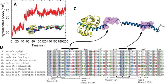
Exposed hydrophobic solvent-accessible surface area (SASA) and potential binding of additional CaMs. (A) Time evolution of hydrophobic SASA during the stretching simulation PIC-sr-1 and the subsequent relaxation simulation PIC-re-1. The forced unfolding of the PT domain results in a large increase of hydrophobic SASA. (Inset) Extended PT domain and the IQ motif in surface representation, colored by residue type (blue, positively charged; red, negatively charged; green, hydrophilic; white, hydrophobic); IQ-bound CaM (yellow, cartoon representation). (B) Sequence alignment of myosin VI PT domains from several species. This study involves the PT domain from Sus scrofa and the S. scrofa myosin VI sequence 834–913 was used for alignment. The alignment was performed using MultiSeq (75), implemented as a plugin in VMD (33). The residues are colored by residue type as in panel A. (Shaded areas) Sequence conservation among all nine sequences. (Lighter-shaded areas) Sequence conservation among more than seven of the nine sequences examined. CaM binding motifs identified are labeled, and the charges of the sequence given (note that for the 1-5-10 motif, the total charge includes contributions from three additional residues preceding the motif (67)). (C) Location of the 1-8-14 and 1-5-10 motifs highlighted in the PT domain. Two transparent purple areas depict the motifs, located at the loop regions. (Cyan) IQ-domain; (yellow) apo-CaM; and (blue) extended PT domain.
Indeed, the PT domain sequence contains CaM binding motifs (67). One such motif is the IQ-motif with a consensus sequence [FILV]Qxxx[RK]Gxxx[RK]xx[FILVWY]. Two more CaM binding motifs suggest themselves at the position of the conserved hydrophobic residues, the 1-8-14 motif and the 1-5-10 motif (67). As shown in Fig. 7 B, the myosin VI PT domain sequence exhibits both the 1-8-14 and the 1-5-10 motif, each occurring twice near the two flexible loops, namely at residues 843–856 and 882–895, as also highlighted in Fig. 7 C. The calmodulin binding motifs typically forms an amphiphilic α-helix with basic and polar residues on one side and hydrophobic residues on the other side. It has been shown that CaM can induce α-helix formation on the target protein (68,69). CaM may then also induce in the present case a transition to an α-helix in the flexible loop regions at the extended PT domain and, thereby, render the domain more rigid (69).
It should also be noted that CaM binding is known to change the tertiary structure of the target protein (70). It is yet unclear how dimerization of the myosin VI medial tail domain leads to the unfolding of the PT domain, although Mukherjea et al. (22) hypothesized that steric hindrance created by MT domain dimerization somehow triggers PT domain unfolding. It is feasible that binding of CaM aids the zig-zag extension process of the PT domain.
Discussion
The focus of our study is the investigation of the zig-zag extension model for the stepping geometry of myosin VI as depicted in Fig. 2 A. The results of steered molecular dynamics simulations suggest, indeed, that the proximal tail (PT) domain of myosin can extend to triple its length and, thereby, create a lever-arm extension long enough to accommodate a step size of 30–36 nm. A fascinating role of calmodulin binding is suggested by our study. Such binding has been studied extensively for a long time (71,72), but the focus has been mainly on what controls the binding (73,74), not so much for which purpose calmodulin binding occurs.
Our simulation results make two suggestions regarding the role of calmodulin binding: First, calmodulin binding at the IQ domain facilitates the extension of the PT domain; calmodulin stabilizes helix I in the PT domain and redirects a force applied on the PT domain such that it dissociates more readily the domain's triple helices without significantly affecting their secondary structure. Second, sequence analysis suggests that additional CaM binding is likely because an extended PT domain exposes two potential CaM binding sites. Apparently, CaM can tip the free energy balance between the PT domain in the three-helix bundle state and in the extended state. As the CaM binding sites are located in a flexible loop area that might be a hindrance to the mechanical function of myosin stepping under load, CaM binding could very well also strengthen the extended PT domain mechanically, rendering the myosin VI lever arm that results from PT domain extension rigid enough for its motor function.
Although our study answered one question, namely if the myosin with associated MT domain can realize a large enough step, it raised new questions regarding the role of CaM binding. Our results, therefore, should stimulate and guide future investigation into the fascinating properties of myosin VI and much beyond.
Acknowledgments
The authors thank H. Lee Sweeney and Monalisa Mukherjea for insightful discussions, and Anne Houdusse for providing the PT domain structure before its publication. Molecular images in this article were rendered using the molecular visualization software VMD (33). VMD was also used for data analysis. All-atom MD simulations discussed here were performed using NAMD (36).
This work was supported by National Science Foundation grant PHY0822613 (to K.S. and P.R.S), and National Institutes of Health grants P41-RR005969 and R01-GM073655 (to K.S.) and R01-GM068625 (to P.R.S). Computer time for simulations was provided by the National Center for Supercomputing Applications and the Texas Advanced Computing Center via Large Resources Allocation Committee grant MCA93S028.
Contributor Information
Paul R. Selvin, Email: selvin@illinois.edu.
Klaus Schulten, Email: kschulte@ks.uiuc.edu.
Supporting Material
References
- 1.Sweeney H.L., Houdusse A. Structural and functional insights into the myosin motor mechanism. Annu. Rev. Biophys. 2010;39:539–557. doi: 10.1146/annurev.biophys.050708.133751. [DOI] [PubMed] [Google Scholar]
- 2.Spudich J.A., Sivaramakrishnan S. Myosin VI: an innovative motor that challenged the swinging lever arm hypothesis. Nat. Rev. Mol. Cell Biol. 2010;11:128–137. doi: 10.1038/nrm2833. [DOI] [PMC free article] [PubMed] [Google Scholar]
- 3.Sweeney H.L., Houdusse A. Myosin VI rewrites the rules for myosin motors. Cell. 2010;141:573–582. doi: 10.1016/j.cell.2010.04.028. [DOI] [PubMed] [Google Scholar]
- 4.Cecchini M., Alexeev Y., Karplus M. Pi release from myosin: a simulation analysis of possible pathways. Structure. 2010;18:458–470. doi: 10.1016/j.str.2010.01.014. [DOI] [PMC free article] [PubMed] [Google Scholar]
- 5.Ovchinnikov V., Trout B.L., Karplus M. Mechanical coupling in myosin V: a simulation study. J. Mol. Biol. 2010;395:815–833. doi: 10.1016/j.jmb.2009.10.029. [DOI] [PMC free article] [PubMed] [Google Scholar]
- 6.Zheng W. Multiscale modeling of structural dynamics underlying force generation and product release in actomyosin complex. Proteins. 2010;78:638–660. doi: 10.1002/prot.22594. [DOI] [PubMed] [Google Scholar]
- 7.Zheng W., Thirumalai D. Coupling between normal modes drives protein conformational dynamics: illustrations using allosteric transitions in myosin II. Biophys. J. 2009;96:2128–2137. doi: 10.1016/j.bpj.2008.12.3897. [DOI] [PMC free article] [PubMed] [Google Scholar]
- 8.Cecchini M., Houdusse A., Karplus M. Allosteric communication in myosin V: from small conformational changes to large directed movements. PLoS Comput. Biol. 2008;4:e1000129. doi: 10.1371/journal.pcbi.1000129. [DOI] [PMC free article] [PubMed] [Google Scholar]
- 9.Tehver R., Thirumalai D. Rigor to post-rigor transition in myosin V: link between the dynamics and the supporting architecture. Structure. 2010;18:471–481. doi: 10.1016/j.str.2010.01.019. [DOI] [PubMed] [Google Scholar]
- 10.Kellerman K.A., Miller K.G. An unconventional myosin heavy chain gene from Drosophila melanogaster. J. Cell Biol. 1992;119:823–834. doi: 10.1083/jcb.119.4.823. [DOI] [PMC free article] [PubMed] [Google Scholar]
- 11.Sweeney H.L., Houdusse A. What can myosin VI do in cells? Curr. Opin. Cell Biol. 2007;19:57–66. doi: 10.1016/j.ceb.2006.12.005. [DOI] [PubMed] [Google Scholar]
- 12.Aschenbrenner L., Naccache S.N., Hasson T. Uncoated endocytic vesicles require the unconventional myosin, Myo6, for rapid transport through actin barriers. Mol. Biol. Cell. 2004;15:2253–2263. doi: 10.1091/mbc.E04-01-0002. [DOI] [PMC free article] [PubMed] [Google Scholar]
- 13.Warner C.L., Stewart A., Buss F. Loss of myosin VI reduces secretion and the size of the Golgi in fibroblasts from Snell's Waltzer mice. EMBO J. 2003;22:569–579. doi: 10.1093/emboj/cdg055. [DOI] [PMC free article] [PubMed] [Google Scholar]
- 14.Avraham K.B., Hasson T., Jenkins N.A. The mouse Snell's Waltzer deafness gene encodes an unconventional myosin required for structural integrity of inner ear hair cells. Nat. Genet. 1995;11:369–375. doi: 10.1038/ng1295-369. [DOI] [PubMed] [Google Scholar]
- 15.Lister I., Schmitz S., Kendrick-Jones J. A monomeric myosin VI with a large working stroke. EMBO J. 2004;23:1729–1738. doi: 10.1038/sj.emboj.7600180. [DOI] [PMC free article] [PubMed] [Google Scholar]
- 16.Park H., Ramamurthy B., Sweeney H.L. Full-length myosin VI dimerizes and moves processively along actin filaments upon monomer clustering. Mol. Cell. 2006;21:331–336. doi: 10.1016/j.molcel.2005.12.015. [DOI] [PubMed] [Google Scholar]
- 17.Yu C., Feng W., Zhang M. Myosin VI undergoes cargo-mediated dimerization. Cell. 2009;138:537–548. doi: 10.1016/j.cell.2009.05.030. [DOI] [PubMed] [Google Scholar]
- 18.Phichith D., Travaglia M., Sweeney H.L. Cargo binding induces dimerization of myosin VI. Proc. Natl. Acad. Sci. USA. 2009;106:17320–17324. doi: 10.1073/pnas.0909748106. [DOI] [PMC free article] [PubMed] [Google Scholar]
- 19.Ménétrey J., Bahloul A., Houdusse A. The structure of the myosin VI motor reveals the mechanism of directionality reversal. Nature. 2005;435:779–785. doi: 10.1038/nature03592. [DOI] [PMC free article] [PubMed] [Google Scholar]
- 20.Wells A.L., Lin A.W., Sweeney H.L. Myosin VI is an actin-based motor that moves backwards. Nature. 1999;401:505–508. doi: 10.1038/46835. [DOI] [PubMed] [Google Scholar]
- 21.Nishikawa S., Homma K., Ikebe M. Class VI myosin moves processively along actin filaments backward with large steps. Biochem. Biophys. Res. Commun. 2002;290:311–317. doi: 10.1006/bbrc.2001.6142. [DOI] [PubMed] [Google Scholar]
- 22.Mukherjea M., Llinas P., Sweeney H.L. Myosin VI dimerization triggers an unfolding of a three-helix bundle in order to extend its reach. Mol. Cell. 2009;35:305–315. doi: 10.1016/j.molcel.2009.07.010. [DOI] [PMC free article] [PubMed] [Google Scholar]
- 23.Sivaramakrishnan S., Spink B.J., Spudich J.A. Dynamic charge interactions create surprising rigidity in the ER/K α-helical protein motif. Proc. Natl. Acad. Sci. USA. 2008;105:13356–13361. doi: 10.1073/pnas.0806256105. [DOI] [PMC free article] [PubMed] [Google Scholar]
- 24.Sweeney H.L., Park H., Rosenfeld S.S. How myosin VI coordinates its heads during processive movement. EMBO J. 2007;26:2682–2692. doi: 10.1038/sj.emboj.7601720. [DOI] [PMC free article] [PubMed] [Google Scholar]
- 25.Pylypenko O., Song L., Sweeney H.L. Role of insert-1 of myosin VI in modulating nucleotide affinity. J. Biol. Chem. 2011;286:11716–11723. doi: 10.1074/jbc.M110.200626. [DOI] [PMC free article] [PubMed] [Google Scholar]
- 26.Rock R.S., Rice S.E., Sweeney H.L. Myosin VI is a processive motor with a large step size. Proc. Natl. Acad. Sci. USA. 2001;98:13655–13659. doi: 10.1073/pnas.191512398. [DOI] [PMC free article] [PubMed] [Google Scholar]
- 27.Ménétrey J., Llinas P., Houdusse A. The structural basis for the large powerstroke of myosin VI. Cell. 2007;131:300–308. doi: 10.1016/j.cell.2007.08.027. [DOI] [PubMed] [Google Scholar]
- 28.Yildiz A., Park H., Sweeney H.L. Myosin VI steps via a hand-over-hand mechanism with its lever arm undergoing fluctuations when attached to actin. J. Biol. Chem. 2004;279:37223–37226. doi: 10.1074/jbc.C400252200. [DOI] [PubMed] [Google Scholar]
- 29.Ökten Z., Churchman L.S., Spudich J.A. Myosin VI walks hand-over-hand along actin. Nat. Struct. Mol. Biol. 2004;11:884–887. doi: 10.1038/nsmb815. [DOI] [PubMed] [Google Scholar]
- 30.Ali M.Y., Homma K., Ikebe M. Unconstrained steps of myosin VI appear longest among known molecular motors. Biophys. J. 2004;86:3804–3810. doi: 10.1529/biophysj.103.037416. [DOI] [PMC free article] [PubMed] [Google Scholar]
- 31.Spink B.J., Sivaramakrishnan S., Spudich J.A. Long single α-helical tail domains bridge the gap between structure and function of myosin VI. Nat. Struct. Mol. Biol. 2008;15:591–597. doi: 10.1038/nsmb.1429. [DOI] [PMC free article] [PubMed] [Google Scholar]
- 32.Kim H., Hsin J., Schulten K. Formation of salt bridges mediates internal dimerization of myosin VI medial tail domain. Structure. 2010;18:1443–1449. doi: 10.1016/j.str.2010.09.011. [DOI] [PMC free article] [PubMed] [Google Scholar]
- 33.Humphrey W., Dalke A., Schulten K. VMD: visual molecular dynamics. J. Mol. Graph. 1996;14:33–38. doi: 10.1016/0263-7855(96)00018-5. 27–28. [DOI] [PubMed] [Google Scholar]
- 34.MacKerell A.D., Jr., Bashford D., Karplus M. All-atom empirical potential for molecular modeling and dynamics studies of proteins. J. Phys. Chem. B. 1998;102:3586–3616. doi: 10.1021/jp973084f. [DOI] [PubMed] [Google Scholar]
- 35.Jorgensen W.L., Chandrasekhar J., Klein M.L. Comparison of simple potential functions for simulating liquid water. J. Chem. Phys. 1983;79:926–935. [Google Scholar]
- 36.Phillips J.C., Braun R., Schulten K. Scalable molecular dynamics with NAMD. J. Comput. Chem. 2005;26:1781–1802. doi: 10.1002/jcc.20289. [DOI] [PMC free article] [PubMed] [Google Scholar]
- 37.Mackerell A.D., Jr. Empirical force fields for biological macromolecules: overview and issues. J. Comput. Chem. 2004;25:1584–1604. doi: 10.1002/jcc.20082. [DOI] [PubMed] [Google Scholar]
- 38.Buck M., Bouguet-Bonnet S., MacKerell A.D., Jr. Importance of the CMAP correction to the CHARMM22 protein force field: dynamics of hen lysozyme. Biophys. J. 2006;90:L36–L38. doi: 10.1529/biophysj.105.078154. [DOI] [PMC free article] [PubMed] [Google Scholar]
- 39.Grubmüller H., Heller H., Schulten K. Generalized Verlet algorithm for efficient molecular dynamics simulations with long-range interactions. Mol. Simul. 1991;6:121–142. [Google Scholar]
- 40.Schlick T., Skeel R., Schulten K. Algorithmic challenges in computational molecular biophysics. J. Comput. Phys. 1999;151:9–48. [Google Scholar]
- 41.Andersen H.C. RATTLE: a “velocity” version of the SHAKE algorithm for molecular dynamics calculations. J. Chem. Phys. 1983;52:24–34. [Google Scholar]
- 42.Miyamoto S., Kollman P.A. SETTLE: an analytical version of the SHAKE and RATTLE algorithm for rigid water molecules. J. Comput. Chem. 1992;13:952–962. [Google Scholar]
- 43.Isralewitz B., Gao M., Schulten K. Steered molecular dynamics and mechanical functions of proteins. Curr. Opin. Struct. Biol. 2001;11:224–230. doi: 10.1016/s0959-440x(00)00194-9. [DOI] [PubMed] [Google Scholar]
- 44.Sotomayor M., Corey D.P., Schulten K. In search of the hair-cell gating spring elastic properties of ankyrin and cadherin repeats. Structure. 2005;13:669–682. doi: 10.1016/j.str.2005.03.001. [DOI] [PubMed] [Google Scholar]
- 45.Lee E.H., Hsin J., Schulten K. Discovery through the computational microscope. Structure. 2009;17:1295–1306. doi: 10.1016/j.str.2009.09.001. [DOI] [PMC free article] [PubMed] [Google Scholar]
- 46.Zeng X., Hu H., Yang W. Equilibrium sampling for biomolecules under mechanical tension. Biophys. J. 2010;98:733–740. doi: 10.1016/j.bpj.2009.11.004. [DOI] [PMC free article] [PubMed] [Google Scholar]
- 47.Izrailev S., Stepaniants S., Schulten K. Steered molecular dynamics. In: Deuflhard P., Hermans J., Leimkuhler B., Mark A.E., Reich S., Skeel R.D., editors. Computational Molecular Dynamics: Challenges, Methods, Ideas. Vol. 4 of Lecture Notes in Computational Science and Engineering. Springer-Verlag; Berlin, Germany: 1998. pp. 39–65. [Google Scholar]
- 48.Lee E.H., Hsin J., Schulten K. Tertiary and secondary structure elasticity of a six-Ig titin chain. Biophys. J. 2010;98:1085–1095. doi: 10.1016/j.bpj.2009.12.4192. [DOI] [PMC free article] [PubMed] [Google Scholar]
- 49.Sotomayor M., Schulten K. Single-molecule experiments in vitro and in silico. Science. 2007;316:1144–1148. doi: 10.1126/science.1137591. [DOI] [PubMed] [Google Scholar]
- 50.Gao M., Sotomayor M., Schulten K. Molecular mechanisms of cellular mechanics. Phys. Chem. Chem. Phys. 2006;8:3692–3706. doi: 10.1039/b606019f. [DOI] [PubMed] [Google Scholar]
- 51.Marszalek P.E., Lu H., Fernandez J.M. Mechanical unfolding intermediates in titin modules. Nature. 1999;402:100–103. doi: 10.1038/47083. [DOI] [PubMed] [Google Scholar]
- 52.Lu H., Isralewitz B., Schulten K. Unfolding of titin immunoglobulin domains by steered molecular dynamics simulation. Biophys. J. 1998;75:662–671. doi: 10.1016/S0006-3495(98)77556-3. [DOI] [PMC free article] [PubMed] [Google Scholar]
- 53.Vemparala S., Saiz L., Klein M.L. Partitioning of anesthetics into a lipid bilayer and their interaction with membrane-bound peptide bundles. Biophys. J. 2006;91:2815–2825. doi: 10.1529/biophysj.106.085324. [DOI] [PMC free article] [PubMed] [Google Scholar]
- 54.Ortiz V., Nielsen S.O., Discher D.E. Unfolding a linker between helical repeats. J. Mol. Biol. 2005;349:638–647. doi: 10.1016/j.jmb.2005.03.086. [DOI] [PubMed] [Google Scholar]
- 55.Serquera D., Lee W., Itzhaki L.S. Mechanical unfolding of an ankyrin repeat protein. Biophys. J. 2010;98:1294–1301. doi: 10.1016/j.bpj.2009.12.4287. [DOI] [PMC free article] [PubMed] [Google Scholar]
- 56.Qin Z., Kreplak L., Buehler M.J. Nanomechanical properties of vimentin intermediate filament dimers. Nanotechnology. 2009;20:425101. doi: 10.1088/0957-4484/20/42/425101. [DOI] [PubMed] [Google Scholar]
- 57.Qin Z., Buehler M.J. Molecular dynamics simulation of the α-helix to β-sheet transition in coiled protein filaments: evidence for a critical filament length scale. Phys. Rev. Lett. 2010;104:198304. doi: 10.1103/PhysRevLett.104.198304. [DOI] [PubMed] [Google Scholar]
- 58.Aprodu I., Soncini M., Redaelli A. Mechanical characterization of actomyosin complex by molecular mechanics simulations. J. Appl. Biomater. Biomech. 2010;8:20–27. [PubMed] [Google Scholar]
- 59.Aprodu I., Soncini M., Redaelli A. Interaction forces and interface properties of KIF1A kinesin-αβ tubulin complex assessed by molecular dynamics. J. Biomech. 2008;41:3196–3201. doi: 10.1016/j.jbiomech.2008.08.014. [DOI] [PubMed] [Google Scholar]
- 60.Aprodu I., Soncini M., Redaelli A. Mechanical characterization of motor proteins: a molecular dynamics approach. Macromol. Theor. Simul. 2008;17:376–384. [Google Scholar]
- 61.Lim B.B., Lee E.H., Schulten K. Molecular basis of fibrin clot elasticity. Structure. 2008;16:449–459. doi: 10.1016/j.str.2007.12.019. [DOI] [PubMed] [Google Scholar]
- 62.Sotomayor M., Vásquez V., Schulten K. Ion conduction through MscS as determined by electrophysiology and simulation. Biophys. J. 2007;92:886–902. doi: 10.1529/biophysj.106.095232. [DOI] [PMC free article] [PubMed] [Google Scholar]
- 63.Hsin J., Strümpfer J., Schulten K. Molecular origin of the hierarchical elasticity of titin: simulation, experiment, and theory. Annu. Rev. Biophys. 2011;40:187–203. doi: 10.1146/annurev-biophys-072110-125325. [DOI] [PubMed] [Google Scholar]
- 64.Hsin J., Schulten K. Improved resolution of tertiary structure elasticity in muscle protein. Biophys. J. 2011;100:L22–L24. doi: 10.1016/j.bpj.2011.01.019. [DOI] [PMC free article] [PubMed] [Google Scholar]
- 65.Maier B., Potter L., Sheetz M.P. Single pilus motor forces exceed 100 pN. Proc. Natl. Acad. Sci. USA. 2002;99:16012–16017. doi: 10.1073/pnas.242523299. [DOI] [PMC free article] [PubMed] [Google Scholar]
- 66.Chuan P., Spudich J.A., Dunn A.R. Robust mechanosensing and tension generation by myosin VI. J. Mol. Biol. 2011;405:105–112. doi: 10.1016/j.jmb.2010.10.010. [DOI] [PMC free article] [PubMed] [Google Scholar]
- 67.Rhoads A.R., Friedberg F. Sequence motifs for calmodulin recognition. FASEB J. 1997;11:331–340. doi: 10.1096/fasebj.11.5.9141499. [DOI] [PubMed] [Google Scholar]
- 68.Padre R.C., Stull J.T. Conformational requirements for Ca2+/calmodulin binding and activation of myosin light chain kinase. FEBS Lett. 2000;472:148–152. doi: 10.1016/s0014-5793(00)01434-4. [DOI] [PubMed] [Google Scholar]
- 69.Zhang Y., Tan H., Jia Z. Investigating the disorder-order transition of calmodulin binding domain upon binding calmodulin using molecular dynamics simulation. J. Mol. Recognit. 2010;23:360–368. doi: 10.1002/jmr.1002. [DOI] [PubMed] [Google Scholar]
- 70.Hoeflich K.P., Ikura M. Calmodulin in action: diversity in target recognition and activation mechanisms. Cell. 2002;108:739–742. doi: 10.1016/s0092-8674(02)00682-7. [DOI] [PubMed] [Google Scholar]
- 71.Yamniuk A.P., Vogel H.J. Calmodulin's flexibility allows for promiscuity in its interactions with target proteins and peptides. Mol. Biotechnol. 2004;27:33–57. doi: 10.1385/MB:27:1:33. [DOI] [PubMed] [Google Scholar]
- 72.Chen Y.-G., Hummer G. Slow conformational dynamics and unfolding of the calmodulin C-terminal domain. J. Am. Chem. Soc. 2007;129:2414–2415. doi: 10.1021/ja067791a. [DOI] [PubMed] [Google Scholar]
- 73.Junker J.P., Ziegler F., Rief M. Ligand-dependent equilibrium fluctuations of single calmodulin molecules. Science. 2009;323:633–637. doi: 10.1126/science.1166191. [DOI] [PubMed] [Google Scholar]
- 74.Best R.B., Hummer G. Unfolding the secrets of calmodulin. Science. 2009;323:593–594. doi: 10.1126/science.1169555. [DOI] [PMC free article] [PubMed] [Google Scholar]
- 75.Roberts E., Eargle J., Luthey-Schulten Z. MultiSeq: unifying sequence and structure data for evolutionary analysis. BMC Bioinformatics. 2006;7:382. doi: 10.1186/1471-2105-7-382. [DOI] [PMC free article] [PubMed] [Google Scholar]
Associated Data
This section collects any data citations, data availability statements, or supplementary materials included in this article.