Abstract
Elasticity-based imaging modalities are becoming popular diagnostic tools in clinical practice. Gelatin-based, tissue mimicking phantoms that contain graphite as the acoustic scattering material are commonly used in testing and validating elasticity-imaging methods to quantify tissue stiffness. The gelatin bloom strength and concentration are used to control phantom stiffness. While it is known that graphite concentration can be modulated to control acoustic attenuation, the impact of graphite concentrationon phantom elasticity has not been characterized in these gelatin phantoms. This work investigates the impact of graphite concentration on phantom shear stiffness as characterized by shear-wave speed measurements using impulsive acoustic-radiation-force excitations. Phantom shear-wave speed increased by 0.83 (m/s)/(dB/(cm MHz)) when increasing the attenuation coefficient slope of the phantom material through increasing graphite concentration. Therefore, gelatin-phantom stiffness can be affected by the conventional ways that attenuation is modulated through graphite concentration in these phantoms.
Keywords: Acoustic radiation force, ARFI, attenuation coefficient slope, elasticity, graphite, phantom, shear wave, stiffness
I. INTRODUCTION
Tissue-mimicking phantoms serve an important role in ultrasound research by simulating soft tissues without the need to experiment on humans or animals. Phantoms are used to test ultrasound scanners and transducers to characterize the performance of these systems. Originally, gelatin-based phantoms using graphite as the attenuating particle were developed and characterized by Madsen and Hall to study B-mode imaging and quasistatic elastography.1, 2 The phantom fabrication procedure utilized in this work was based on that of Hall et al,1 where graphite was used to control acoustic scattering. Phantom fabrication research has shown that specific materials in graphite phantoms control different acoustic and material properties; for example, the concentration of alcohol can be used to vary the longitudinal sound speed and the graphite concentration can modulate the attenuation-coefficient slope.1-3 Now that these types of phantoms are being used for dynamic elasticity imaging, the impact of varying graphite concentration on the phantom’s elasticity (i.e., stiffness) needs to be quantified for parametric studies demanding known acoustic attenuation-coefficient slopes and shear stiffnesses.4,5
Many different noninvasive, ultrasound-based imaging modalities can be used to measure tissue elasticity, such as Supersonic Shear Imaging (SSI),6 Shear Wave Elasticity Imaging (SWEI),7 Spatially Modulated Ultrasound Radiation Force (SMURF),8 Shearwave Dispersion Ultrasound Vibrometry (SDUV) and FibroScan®.9, 10 By estimating the speed of propagating shear waves (cT) generated by acoustic-radiation force or external vibration, the shear modulus (μ) of the medium can be related to the shear-wave speed under the assumptions that (1) the shear wave is traveling in the lateral direction in the imaging plane (perpendicular to the radiation force excitation axis of symmetry), (2) the medium is linear and homogeneous and (3) there is negligible dispersion in the region of interest (i.e., perfectly elastic), by:
| (1) |
where ρ represents the density of the medium (typically ρ = 1.0 g/cm3 in soft tissues). The radiation force in an absorbing medium has been described by Torr and Nyborg, where F̄ represents the radiation force, c is the longitudinal sound speed, α is the absorption coefficient and Ī is the spatially-localized temporal average intensity:11, 12
| (2) |
Acoustic radiation force-generated shear-wave speed reconstructions were used to quantify the stiffness of the phantoms fabricated in this study.13 Section II outlines the material and methods used for the phantom fabrication and the measurement of the shear stiffness, acoustic attenuation coefficient slope and sound speed. Section III presents the results of these measurements, while section IV discusses the impact that modulating the phantom attenuation-coefficient slope with varying graphite concentration has on phantom stiffness.
II. MATERIALS AND METHODS
Phantom fabrication
The procedure for phantom fabrication can be found in Hall and Bilgen,1 with table 1 of this article outlining the specific materials used during fabrication in these studies. Two-hundred bloom strength, porcine gelatin (Gelatin Innovations Inc., Franklin Park, IL, USA) was used along with glutaraldehyde (2.2% in H2O) to accelerate gelatin cross-linking. The gelatin bloom strength and concentration were held constant for all of the phantoms in these studies; graphite concentration was the only variable that was modulated in the phantom fabrication process. Graphite (4239 vein graphite, approximately 17μm particle size, Superior Graphite, Chicago, IL, USA) concentrations of 5%, 8%, 10% and 12.4% by mass were used to modulate the acoustic attenuation of the phantoms. A minimum graphite concentration of 5% was used because acoustic attenuation is required to generate acoustic radiation force (Eq. (2)); therefore, a graphite concentration of zero could not be tested because no shear waves could be generated in these phantoms with acoustic-radiation force. A custom Teflon® phantom mold was used to make standardized phantom dimensions, with a top diameter of 6.5 cm and a bottom diameter of 7.5 cm, with a height of 6.5 cm. The phantom tapering allowed the phantoms to be easily removed from the fabrication mold without any damage, allowing for uniform phantoms to be compared. The phantoms were rotated at 20 rpm using a custom-designed rotation apparatus for 24 hours while gelatin cross-linking was completed to insure a uniform distribution of graphite in the phantoms.
TABLE 1.
Phantom materials.
| Material | Volume (ml) | Weight (g) | % Weight |
|---|---|---|---|
| DI water | 285 | 285 | 78.6 |
| N-propanol | 14 | 11.3 | 3.1 |
| Gelatin | 18 | 5.0 | |
| Glutaraldehyde | 3 | 3.1 | 0.9 |
| Graphite | 16.7, 27.6, 35.3, 45 | 5, 8, 10, 12.4 |
Shear-wave speed measurements
Acoustic Radiation Force Impulse (ARFI) shear-wave imaging was used during this testing to find the shear-wave speeds of the phantoms using a Siemens ACUSON™ S2000 scanner (Siemens Medical Solutions, Inc. Ultrasound Division, Issaquah, WA, USA) and a Siemens 4C1 transducer operating with the specific parameters listed in table 2.13
TABLE 2.
Ultrasound-transducer configurations for shear-wave speed measurements at multiple focal depths using a nominal excitation frequency of 2.3 MHz.
| Focal depth (cm) | 1.5 | 3.0 | 4.9 |
| PRF (kHz) | 10.3 | 9.8 | 7.8 |
| F-number | 2 | 2 | 2 |
Three phantoms were fabricated for each graphite concentration specified in table 1. The shear-wave speeds were found at depths of 1.5, 3.0 and 4.9 cm at the left, middle and right sides of the B-mode imaging plane centered in the phantom to characterize stiffness heterogeneity. All the measurements were repeated twice in each location for a total of 18 shear wave speeds for each phantom. An average shear-wave speed was found for each phantom along with a standard deviation from the nine imaging locations in each phantom. Measurements were taken within one week of phantom fabrication in a room temperature environment and they were stored under mineral oil to prevent desiccation in air. The shear-wave speed data do not show any significant changes in stiffness within the first week of fabrication (data not presented in this article).
Shear-wave speeds were reconstructed with a time-of-flight algorithm using laterally-offset time-to-peak (TTP) measurements, as detailed by Palmeri and Wang13, 14 using the same assumptions associated with Eq. (1). Using the depth of field corresponding to a particular focus, the Random Sample Consensus (RANSAC) algorithm was used to estimate the average shear wave speeds, as detailed by Wang et al.14
Attenuation-coefficient slope and sound-speed measurements
Attenuation-coefficient slope and sound-speed measurements were made using the experimental setup outlined by Madsen et al.11 A Siemens SONOLINE™ Antares ultrasound scanner with a Siemens CH4-1 transducer using 10 cycle, 2.22 MHz nominal excitation push pulses focused at 8 cm in an F/2 configuration at 5% power (low power to avoid nonlinearity propagation artifacts in water) was used for these measurements. The acoustic pulses were characterized using hydrophone (Sonic Technologies, Model 804, now Sonora Medical Systems, Longmont, CO, USA) data acquired with a digital oscilloscope (Tektronix, Oregon, USA, Model TDS5032B) and custom LabVIEW (Texas Instruments, Austin, TX, USA) programs. The hydrophone was placed at the focal depth (8 cm). Attenuation coefficient slopes were measured using the spatial peak-pulse average intensity (ISPPA) at the hydrophone after propagating through each phantom and comparing that to the value obtained from nonattenuating water. Intensity measurements in water were performed after each phantom was tested to insure consistent and repeatable water averages and environmental variables (e.g., temperature). Attenuation-coefficient slopes were calculated for each phantom using Eq. (3), with D representing the phantom thickness (6.5 cm) and f representing the ultrasound frequency (2.22 MHz):
| (3) |
Sound speeds were measured for each phantom using time-of-flight calculations with 0.1 μs resolution. The substitution method was used to find the sound speed (Eq. (4)), where Δt represents the through-transmission time delay, cw is the speed of sound in water, which was calculated for the specific temperature of the water bath during each experiment, cp is the sound speed of the phantom and D is of the thickness of the phantom:15
| (4) |
III. RESULTS
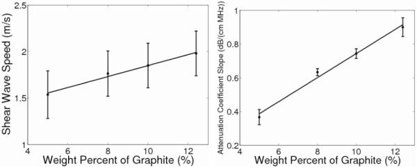
The shear-wave speeds in figure 1 (left) linearly increase with increasing graphite concentration (R2 = 0.99, p < 0.01) with a slope of 0.06 (m/s)/[% graphite]. Table 3 displays the results obtained from averaging the measurements over all three phantoms fabricated for each graphite concentration. The standard deviations represent the variability over the nine different imaging locations for the shear-wave-speed measurements. The data collected contained 95% inliers using the RANSAC shear-wave-speed calculation, with a corresponding stiffness precision of 0.1m/s.14 An ANOVA was performed, along with a two-sampled, unpaired t-test, to test the null hypothesis that the shear-wave speeds do not change with graphite concentration. Both statistical analyses determined the shear-wave speeds for phantoms of 10% and 12.4 % graphite to be significantly different from that of the 5% graphite phantom while the shear-wave speed of the 8% graphite phantom did not differ significantly from that of any of the other phantoms.
Fig. 1.
Shear-wave speed as a function of graphite concentration (left), with the standard deviations representing the variability over nine different imaging locations. There is a linear correlation between these quantities (R2 = 0.99, p < .01) with a slope of 0.06 (m/s) / [% graphite]. Attenuation coefficient slope as a function of weight percent graphite (right) has a linear correlation as well (R2 = 0.99, p < 0.01) with a slope of 0.07 (dB/(cm MHz)) / [% graphite] with standard deviations over the replicate phantoms.
TABLE 3.
Measured shear-wave speeds, attenuation-coefficient slopes and sound speeds for different graphite concentrations.
| % Graphite | Shear-wave speed (m/s) |
Attenuation-coefficient slope (dB/(cm MHz)) |
Sound speed (m/s) |
|---|---|---|---|
| 12.4 | 1.98±0.24 | 0.90±0.06 | 1532±11.6 |
| 10 | 1.84±0.27 | 0.74±0.03 | 1527±8.3 |
| 8 | 1.76±0.24 | 0.63±0.02 | 1540±3.6 |
| 5 | 1.54±0.26 | 0.36±0.05 | 1532±4.2 |
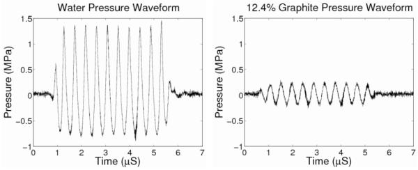
As previously demonstrated by Madsen et al,2 table 3 and figure 1(right) show that the acoustic-attenuation-coefficient slope increases linearly with increasing graphite concentration (R2 = 0.99, p < 0.01). The wave forms for both water and 12.4% graphite hydrophone measurements are shown in figure 2(left) and (right), respectively. The power spectrum was found for the waveforms with a maximum peak-amplitude frequency of 2.3 MHz, confirming the set nominal frequency of the scanner to be within 2% of the measured center frequency. Additionally, the longitudinal sound speed does not depend upon graphite concentration (p = 0.27). Due to the precision of the oscilloscope measurements being 0.1 μs, the accuracy of the sound speeds is limited to ~10%. The standard deviations reported in table 3 for the attenuation-coefficient slope and sound speed represent the variability among the three phantoms fabricated for each graphite concentration.
Fig. 2.
Pressure waveforms for the water and 12.4% graphite phantom. These waveforms show the large pressure amplitude decrease when the phantom is placed between the ultrasound transducer and the hydrophone and confirmed the frequency content of the through-transmission pulse at 2.3 MHz.
Figure 3 shows that shear-wave speed is dependent on attenuation-coefficient slope (as modulated by increasing the graphite concentration) with the shear-wave speed increasing at 0.83 (m/s)/(dB/(cm MHz)) (R2 = 0.99). The graphite phantoms had uniform B-mode images, supporting a homogeneous composition with repeatable results, as exemplified in figure 4.
Fig. 3.
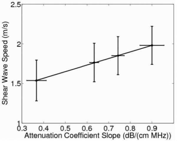
Shear-wave speed as a function of attenuation-coefficient slope modulated by graphite concentration with a slope of 0.83 (m/s)/(dB/(cm MHz)) (R2 = 0.99, p < 0.01.) The shear-wave speed error bars represent variability over the nine different imaging locations in each phantom while the error bars of the attenuation-coefficient slope represent the variability associated with the hydrophone measurements over three replicate phantoms.
Fig. 4.
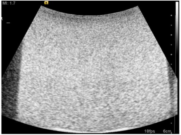
The B-mode image shows the homogeneous echogenicity that was common among all of the graphite phantoms. The side dark regions and white lines on the bottom show the edge of the phantom and beaker, not heterogeneities in phantom composition.
IV. DISCUSSION
Madsen et al characterized the effect of graphite concentration on the attenuation-coefficient slope and sound speed when investigating the properties of tissue-mimicking phantoms.2 The attenuation-coefficient slope values reported in this manuscript are consistent with the data from Madsen et al with a maximum percent error of 2.2% between mean values.2 The stability of the sound speeds for different graphite concentrations was also demonstrated in our studies (Table 3).
All data in these studies were acquired within seven days of phantom fabrication. Data not presented in this article showed that the phantom properties studied in this work were stable within the first week post-fabrication. Due to the continual cross linking in the phantom, there has been some testing to determine how the shear-wave speed of the phantom changes with its stiffness over time; however, the true temporal stability of these results over longer time durations (weeks/months) needs to be explored in future studies.
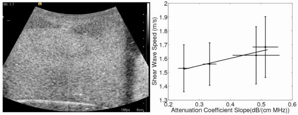
The use of cornstarch as an alternative attenuating in gredient to graphite has also been investigated in imaging research since it can be easier to clean in the fabrication environment.16 The cornstarch phantoms were fabricated using the same procedure as the graphite phantoms and an ANOVA and unpaired t-test demonstrated that shear-wave speeds did not significantly vary with cornstarch concentration. The attenuation-coefficient slopes were much smaller compared to those of the graphite phantoms and the speed was shown to change at a rate of 0.53 (m/s)/(dB/ (cm MHz)) (Fig. 5). These cornstarch phantoms, however, suffered from heterogeneity in their B-mode images (Fig. 5), most likely caused by air bubbles or settling of the cornstarch, resulting in B-mode brightness gradients. These difficulties in achieving a uniform distribution of cornstarch in the gelatin mixture during fabrication were especially challenging at the higher cornstarch concentrations. Despite the heterogeneity in the B-mode images, the cornstarch shear-wave speeds remained consistent throughout the four different cornstarch phantoms. The attenuation coefficient slopes for the cornstarch phantoms were also much lower than the gelatin phantoms, limiting their use for mimicking tissues that have attenuation coefficient slopes greater than 0.5 dB/ (cm MHz). These fabrication concerns limit the utility of cornstarch as an adequate material for radiation-force-based experiments. These heterogeneities could also cause displacement variations in elasticity-imaging experiments depending on their location in a phantom. Also, smaller displacements are generated in the cornstarch phantoms be cause of the smaller attenuation-coefficient slopes and the resulting smaller radiation-force amplitudes (Eq. (2)). Given the heterogeneities associated with the cornstarch phantoms, these data are only presented in the context of a discussion to consider the impact of attenuating materials on phantom stiffness, not to provide conclusive quantitative dependencies as demonstrated in the graphite phantoms.
Fig. 5.
Shear-wave speed as a function of attenuation coefficient slope controlled by weight percent of cornstarch is shown with a slope of 0.053 (m/s)/(dB/(cm MHz)) (R2 = 0.97, p = 0.034). The error bars of the shear-wave speed represent variability over the nine different imaging locations in each phantom while the error bars of the attenuation-coefficient slope represent the variability associated with the hydrophone measurements over the replicate three phantoms. The B-mode image (left) shows the heterogeneity that existed in some of the cornstarch phantoms. The top of the phantom has two hypoechoic regions on both sides and an uneven echogenicity in the middle of the phantom that was worse in the more attenuating phantoms.
Other types of phantoms are currently being researched to day, especially in the field of ultrasonic tissue characterization. Anderson et al are investigating the importance of glass beads in phantoms by modulating the size of the glass spheres to change the backscatter coefficient for use in tissue characterization studies.17 Madsen et al has also used glass beads as an attenuating material, sometimes in combination with graphite.18 Acoustically-heterogeneous phantoms are also being explored to accurately mimic the complexities of soft tissues. The observed differences between graphite and cornstarch acting as attenuating particles in our studies highlight the need to consider each phantom materials impact on phantom stiffness when altering the fabrication procedures and should also be considered as a variable in these glass-bead phantoms when they are used for elasticity-imaging applications.
V. CONCLUSIONS
Ultrasonic elasticity experiments require phantoms with known acoustic and stiffness properties to accurately model soft tissues. Modulating graphite concentrations in gelatin phantoms to achieve variable acoustic attenuation coefficient slopes can affect the resulting shear wave speed by 0.83 (m/s)/ (dB/ (cm MHz), indicating that gelatin concentrations need to be adjusted to maintain constant phantom stiffnesses over a range of different acoustic attenuation coefficient slopes. The effect of other attenuating media (e.g., glass beads) on phantom stiffness should be considered when using phantoms for calibrated elasticity imaging studies.
ACKNOWLEDGEMENTS
The authors would like to thank Siemens Healthcare, Ultrasound Business Unit for their technical support. This work was supported by grants NIH R01 CA142824 and NIH ROI EB002132. We would also like to thank Dr. Kathy Nightingale for her insights and Michael Wang for his help with the RANSAC algorithm.
REFERENCES
- 1.Hall TJ, Bilgen M, Insana MF, Krouskop TA. Phantom materials for elastography. IEEE Trans Ultrason Ferroelec Freq Contr. 1997;44:1355–1365. [Google Scholar]
- 2.Madsen EL, Zagzebski JA, Banjavie RA, Jutila RE. Tissue mimicking materials for ultrasound phantoms. Med Phys. 1978;5:391–394. doi: 10.1118/1.594483. [DOI] [PubMed] [Google Scholar]
- 3.Burlew MM, Madsen EL, Zagzebski JA, Banjavic RA, Sum SW. A new ultrasound tissue-equivalent material. Radiology. 1980;134:517–520. doi: 10.1148/radiology.134.2.7352242. [DOI] [PubMed] [Google Scholar]
- 4.Nightingale K, Soo M, Nightingale R, Trahey G. Acoustic radiation force impulse imaging: In vivo and ex vivo results. Ultrasound Med Biol. 2003;2:1715–1723. doi: 10.1016/s0301-5629(01)00499-9. [DOI] [PubMed] [Google Scholar]
- 5.Chaturvedi P, Insana MF, Hall TJ. Testing the limitations of 2-D companding for strain imaging using phantoms. IEEE Trans Ultrason Ferroelec Freq Contr. 1998;45:1022–1031. doi: 10.1109/58.710585. [DOI] [PubMed] [Google Scholar]
- 6.Bercoff J, Tanter M, Fink M. Supersonic shear imaging: a new technique for soft tissue elasticity mapping. IEEE Trans Ultrason Ferroelec Freq Contr. 2004;51:396–409. doi: 10.1109/tuffc.2004.1295425. [DOI] [PubMed] [Google Scholar]
- 7.Sarvazyan AP, Rudenki OV, Swanson SD, Fowlkes JB, Emelianov SY. Shear wave elasticity imaging: a new ultrasonic technology of medical diagnostics. Ultrasound Med Biol. 1998;24:1419–1435. doi: 10.1016/s0301-5629(98)00110-0. [DOI] [PubMed] [Google Scholar]
- 8.McAleavey S, Collins E, Kelly J, Elegbe E. Validation of SMURF estimation of shear modulus in hydrogels. Ultrasonic Imaging. 2009;31:131–150. doi: 10.1177/016173460903100204. [DOI] [PMC free article] [PubMed] [Google Scholar]
- 9.Chen S, Urban M, Pislaru C, Kinnick R, Zheng Y, Yao A, Greenleaf J. Shearwave dispersion ultrasound vibrometry (SDUV) for measuring tissue elasticity and viscosity. IEEE Trans Ultrason Ferroelec Freq Contr. 2009;56:55–62. doi: 10.1109/TUFFC.2009.1005. [DOI] [PMC free article] [PubMed] [Google Scholar]
- 10.Foucher J, Chanteloup E, Vergniol J, et al. Diagnosis of cirrhosis by transient elastography (Fibroscan): a prospective study. Gut. 2006;55:403–408. doi: 10.1136/gut.2005.069153. [DOI] [PMC free article] [PubMed] [Google Scholar]
- 11.Torr GR. The acoustic radiation force. Amer J Phys. 1984;52:402–408. [Google Scholar]
- 12.Nyborg W. Physical Acoustics. Academic Press Inc; New York: 1965. Acoustic streaming. [Google Scholar]
- 13.Palmeri ML, Wang MH, Dahl JJ, Frinkley KD, Nightingale KR. Quantifying hepatic shear modulus in vivo using acoustic radiation force. Ultrasound Med Biol. 2008;34:546–558. doi: 10.1016/j.ultrasmedbio.2007.10.009. [DOI] [PMC free article] [PubMed] [Google Scholar]
- 14.Wang MH, Palmeri ML, Rotemberg VM, Rouze NC, Nightingale KR. Improving the robustness of time-of-flight based shear wave speed reconstruction methods using RANSAC in human liver in vivo. Ultrasound Med Biol. 2010;36:802–813. doi: 10.1016/j.ultrasmedbio.2010.02.007. [DOI] [PMC free article] [PubMed] [Google Scholar]
- 15.Rossman P, Zagzebski J, Mesina C, Sorenson J, Mazess R. Comparison of speed of sound and ultrasound attenuation in the os calcis to bone density of the radius, femur and lumbar spine. Clini Phys Physiol Meas. 1989;10:353–360. doi: 10.1088/0143-0815/10/4/007. [DOI] [PubMed] [Google Scholar]
- 16.Zemp RJ, Kim C, Wang LV. Ultrasound-modulated optical tomography with intense acoustic bursts. Appl Opt. 2007;46:1615–1623. doi: 10.1364/ao.46.001615. [DOI] [PubMed] [Google Scholar]
- 17.Anderson J, Herd M, King MR, et al. Interlaboratory comparison of backscatter coefficient estimates for tissue mimicking phantoms. Ultrasonic Imaging. 2009;32:48–64. doi: 10.1177/016173461003200104. [DOI] [PMC free article] [PubMed] [Google Scholar]
- 18.Madsen EL, Frank GR, Krouskop TA, et al. Tissue mimicking oil-in-gelatin dispersions for use in heterogeneous elastography phantoms. Ultrasonic Imaging. 2003;25:17–38. doi: 10.1177/016173460302500102. [DOI] [PubMed] [Google Scholar]


