Abstract
We present a Fourier domain mode locking (FDML) fiber laser with a feedback loop allowing automatic startup without a priori knowledge of the fundamental drive frequency. The feedback can also regulate the drive frequency making the source robust against environmental variations. A control system samples the energy of the light traversing the FDML cavity and uses a voltage controlled oscillator (VCO) to drive the tunable fiber Fabry-Perot filter in order to maximize that energy. We demonstrate a prototype self-starting, self-regulating FDML operating at 40 kHz with a full width tuning range of 140 nm around 1305 nm and a power output of ~40 mW. The laser starts up with no operator intervention in less than 5 seconds and exhibits improved spectral stability over a conventional FDML source. In OCT applications the source achieved over 120 dB detection sensitivity and an ~8.9-µm axial resolution.
OCIS codes: (110.4500) Optical coherence tomography; (140.3600) Lasers, tunable
1. Introduction
Swept lasers have become an attractive light source for optical coherence tomography (OCT), offering high imaging speed, narrow instantaneous linewidth and improved detection sensitivity [1–3]. Several implementations of swept lasers have been described in literature such as mechanical scanning [4–7], tunable filtering of fiber ring lasers [3] and Fourier domain mode locking (FDML) lasers [8]. In particular, an FDML fiber laser incorporates a delay line in a circular loop wherein a range of wavelengths are continuously propagating and being amplified. Particular wavelengths are made available as a function of time using a tunable filter synchronized to the round-trip propagation delay.
One of the many advantages of FDML lasing is that within the loop cavity, lasing occurs at all wavelengths simultaneously avoiding the buildup time for laser operation leading to sweep rates limited only by the tunable filter. The recursive amplification also leads to high power output. These advantages have led to considerable interest in FDML sources, with recent reports on ultra-high speed OCT imaging [9–12], OCT data sampling algorithms [13], high output power sources [14] among others.
The operation and stability of an FDML source critically depends on the synchronization of the tunable filter drive frequency with the light circulation frequency in the delay loop. This poses two challenges. First, conventional FDML sources use a high resolution function generator to manually tune the drive frequency while the extent of synchronization is assessed by the operator by observing the time-dependent spectrum of the source. This is an inherently subjective procedure requiring some expertise. Secondly, due to changes in environmental conditions like the temperature and humidity, the optical path length of the delay loop may change leading to a loss of synchronization between the present drive frequency and the circulation frequency. This manifests as spectral fluctuations in the source output which can be detrimental to the system operation.
We present an FDML source with a control system incorporating a voltage controlled oscillator (VCO) in a feedback configuration that seeks to adjust the drive frequency of the tunable filter such that the energy of the light traversing the loop is maximized. This approach addresses both of the issues described earlier. The source can be started up without a priori knowledge of the fundamental drive frequency. The control system scans a broad range of frequencies, iteratively narrowing the range and arriving at the optimal frequency with no manual intervention. After startup, the control system monitors the power output and can retune the drive frequency if a deviation exceeds a predetermined threshold. We analyze the hypothesis underlying the feedback scheme and describe the electrical and optical implementation thereof. We prototyped a self-starting, self-regulating FDML (SS-FDML) source operating with a 140 nm full width tuning range around 1305 nm sweeping at 40 kHz with a power output of ~40 mW. Characterization results indicating optimal and rapid automatic startup and improved spectral stability over a conventional FDML source are presented. OCT imaging at 40,000 axial scans per second using the source is also demonstrated.
2. System architecture
The hypothesis behind our proposed scheme is that an FDML source works optimally when the tunable filter drive frequency is perfectly matched with the light circulation frequency. Intuitively, this is easy to envision considering a single wavelength. When perfect synchronization is achieved, the wavelength passes through the filter with minimal attenuation and is recursively amplified till some equilibrium value of output power is reached. In case of a mismatch, the wavelength will undergo larger than minimal attenuation through the filter and the equilibrium value will be smaller. The argument can be extended to a continuum of wavelengths and thus the average energy will peak at perfect synchronization.
2.1 Optical subsystem
Figure 1a shows a schematic of the SS-FDML source. The FDML loop consisted of a 5-km-long SMF-28e fiber loop, a semiconductor optical amplifier (BOA1132, Covega, MD) with a full width half maximum (FWHM) bandwidth of 90 nm centered at 1305 nm, a tunable filter (Lambda Quest, CA) with a finesse of 700 and a free spectral range (FSR) of 160 nm, a polarization controller, two isolators and a 70/30 coupler OC1 which feeds 30% of the light back into the loop. Based on the optical path length the nominal light transit time is 25 µs leading to a drive frequency around 40 kHz. The timing gate [8] of the system is ~15 ns. A subsequent off-loop 95/5 coupler OC2 diverted 5% of the light to a photodiode and the rest of the light was sent to the imaging system. The instantaneous output of the photodiode represents the light intensity traversing the FDML loop.
Fig. 1.
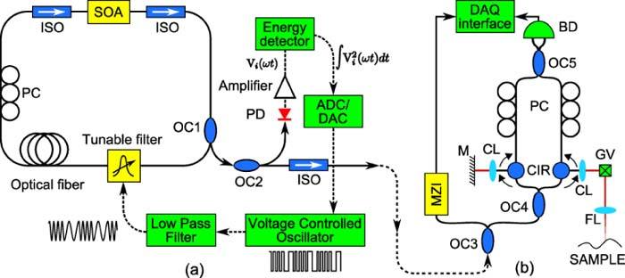
Schematic diagrams of (a) the self-starting, self-regulating FDML laser and (b) swept source OCT system. PC: polarization controller, ISO: isolator, SOA: semiconductor optical amplifier, OC: optical coupler, PD: photodiode, M: mirror, CIR: circulator, GV: galvanometer mirror, CL: collimating lens, FL: focusing lens, PC: polarization controller, BD: balanced detector, DAQ: data acquisition card
2.2 Electronic subsystem
The photodiode output was sent to a custom-designed energy detector based on a 10 MHz four-quadrant analog multiplier integrated circuit (MPY634, Texas Instruments, TX). The multiplier output was digitized to 16 bits at 800 kS/s using a data acquisition (DAQ) card. The DAQ card also implemented a 16 bit digital-to-analog converter (DAC) which was used to drive a signal generator (33220A, Agilent, CA) configured as a voltage controlled oscillator (VCO) by using the external modulation function. The VCO has an RMS jitter of 3.5 ns which is within the timing gate. The VCO output frequency is given by fc + Δf∙vin where fc and Δf are programmable VCO parameters and the vin is the drive voltage. The VCO outputs a square wave while the tunable filter typically requires a sinusoidal drive waveform. Taking advantage of the fact that a square wave consists only of the fundamental frequency (f) and odd harmonics (3f, 5f ...), we designed a low pass filter to convert it to a sine wave. For stable operation, the filter drive waveform must have very low distortion, requiring a very steep filter roll-off over one half of a decade (f to 3f). Thus, we used a three-stage Sallen-Key filter and implemented a 6th order low pass Butterworth filter with a cutoff frequency of 50 kHz and a 120 dB/decade roll-off. This filter can convert square waves between 35 to 45 kHz to sine waves with a distortion between −48 to −62 dB and a maximum signal attenuation of 1.1 dB.
2.3 Feedback control system
At startup, the DAC is swept over its full scale, which translates to a frequency sweep over an arbitrary range set by fc and Δf, with the constraint that this range should contain the fundamental frequency of the FDML which can be roughly estimated according to the total fiber length of the FDML laser loop. The RMS of the output optical energy is monitored during the sweep and the maximum found. In subsequent sweeps, the DAC is swept between two voltages which are given by the VCO drive voltages corresponding to one step before and one after the voltage at which the maximum was found in the previous sweep. The process is repeated until the sweep step is less than one least significant bit (LSB) of the DAC.
2.4 OCT subsystem
The OCT setup is shown in Fig. 1b and consisted of a 95/5 coupler OC3 which sends 5% of the light to a Mach-Zehnder Interferometer (MZI), a 70/30 coupler OC4 which sends 70% of the light to the sample arm and the rest to the reference arm via a circulator in each branch. The sample arm light was scanned using a galvanometer mirror GV. The light coming back from both arms was recombined using a 50/50 coupler OC5 and sent to a balanced detector BD. The MZI and the balanced detector outputs were sent to a high-speed data acquisition module for digitization, display and storage.
3. Results
3.1 System characterization
Figure 2 illustrates the measured characteristics of the low-pass filter. Square wave inputs and the filter output were observed on an oscilloscope and saved for offline Fourier analysis. The figure shows the power spectra of the filter output at 35, 40 and 45 kHz. The data indicates square-to-sine conversion over the frequency range of interest with a worst case third harmonic distortion of −47.9 dB at 35-kHz square wave input.
Fig. 2.
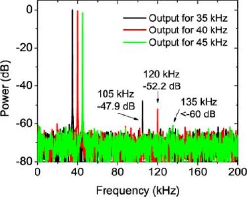
Spectra of filter output for 35, 40 and 45 kHz square wave inputs indicating low distortion square-sine conversion.
The startup is best demonstrated by observing the evolution of the various parameters on an oscilloscope during the sequence. Figure 3a shows four frames from a video sequence (Media 1 (2.1MB, MOV) ) of an oscilloscope monitoring the VCO drive voltage (green), the photodiode output (cyan) and the MZI output (magenta). Figure 3b shows a plot of the RMS light energy traversing the loop for different VCO drive voltages and the VCO output frequency. The video frames in Fig. 3a represent snapshots of the parameters at the four time points which are marked in Fig. 3b. Initially the drive voltage is seen to sweep across ±5 V and the photodiode only shows a very small disturbance. In subsequent sweeps, the drive voltage range is progressively smaller and the photodiode output grows. Since the MZI is much more sensitive to stable FDML operation, in later sweeps, as the FDML approaches stability, the MZI signal can also be seen to increase. The entire startup sequence completes in less than 5 seconds. Figure 4a shows four consecutive sweeps illustrating the iterative search for the operating point. Each sweep range is a subset of the previous one and results in a better estimate of the operating point, as seen by the increasing peak energy. Figure 4b shows the evolution of the operating point in terms of the drive frequency and the light energy over time. The trace plots the peaks seen in Fig. 4a against respective sweep indices. As can be seen, the FDML source stabilizes within 4-5 sweeps. In general, the time needed for convergence depends on the resolution and speed of the ADC, DAC and the VCO. Factors affecting this include the number of points per sweep and the rate and initial range of sweeps. There is a tradeoff between accuracy of the convergence and the convergence time. This is because faster sweeping does not give sufficient time for accurate power measurements. Based on our components, we used 10 points per iteration, a VCO sweep rate of 100 ms per output frequency and a 2 kHz initial search range. It is worth noting that the VCO output filter distortion around 40 kHz, the eventual operating frequency of the FDML, is under −52 dB (Fig. 2). This performance from the square-to-sine converter is critical for proper startup.
Fig. 3.
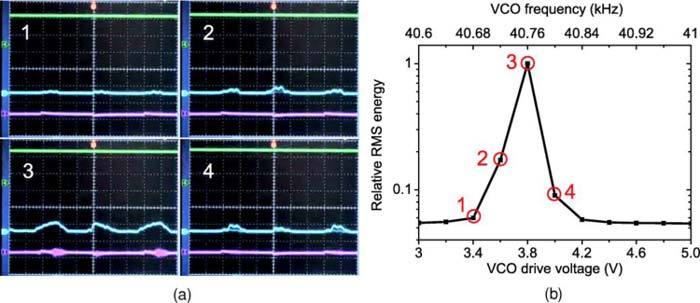
(a) Oscilloscope snapshots (Media 1 (2.1MB, MOV) ) at points marked in (b) showing VCO drive voltage (green), photodiode output (cyan) and MZI output (magenta); (b) Evolution of optical energy with VCO drive voltage (lower horizontal axis) and the corresponding output frequency (upper horizontal axis).
Fig. 4.
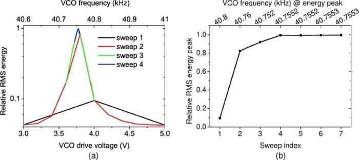
(a) Four consecutive sweeps showing recursive search; (b) Convergence of peak energy.
In order to evaluate the stability of the system, we monitored the output spectrum of the source every 10 minutes for a period of 2 hours using an optical spectrum analyzer. Figure 5a shows all the thirteen spectra. For each wavelength, we defined the spectral fluctuation as the ratio of the standard deviation to the mean of the intensity measurements. Figure 5b shows that this data for both the conventional and the SS-FDML. This measurement was done in a controlled laboratory environment leading to a relatively low instability in the conventional FDML However, the self-starting, self-regulating FDML exhibits increased stability due to the feedback control. To further demonstrate the regulating ability of the SS-FDML we used a thermal blanket to wrap the fiber spool and heat the air around it. For a conventional FDML, a 4 centigrade increase caused the RMS energy to drop to ~40% of the initial value and the MZI
Fig. 5.
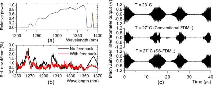
(a) Self-starting, self-regulating FDML (SS-FDML) spectra measured every ten minutes over two hours; (b) Spectral fluctuations with and without feedback over two hours; (c)Effect of temperature variation on conventional and SS-FDML.
signal deteriorated as shown in Fig. 5c. The figure also shows the output for the SS-FDML where the power was maintained at 95% of the initial level. The feedback loop achieves this by sensing the power loss and re-optimizing the drive frequency.
3.2 Optical coherence tomography
We tested the performance of the SS-FDML source for OCT imaging in the setup shown in Fig. 1b and described in Sec. 2.4. Figure 6a shows the point spread function (PSF) measured across a 2.3 mm imaging depth indicating a roll-off of 7.5 dB. The spurious peaks seen in the data are due to back reflections in the system. Figure 6b illustrates the detail of one of the PSFs showing an axial resolution of 8.9 µm in air. Measurements also indicated a detection sensitivity of over 120 dB with a power of 10 mW in the sample arm.
Fig. 6.
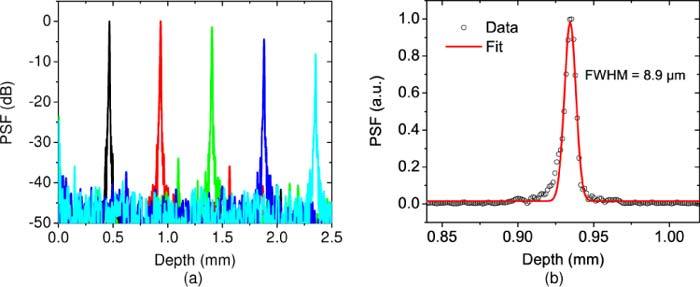
Point spread function (PSF) measured for a range of imaging depths indicating a 7.5 dB roll-off over 2.3 mm (b) Detail of the PSF showing an 8.9 µm axial resolution.
OCT imaging of a human fingertip was performed at 40,000 axial scans per second using a handheld scanning probe. Figure 7 shows a representative image from a video sequence obtained at 40 frames per second. The imaging field of view is about 3 mm (2048 pixels) lateral × 1.8 mm (1024 pixels) deep. The keratinized dead cells forming the top layer of the epidermis, the stratum corneum, followed by the living cell epidermal layers - stratum lucidum, stratum granulosum, stratum spinosum and stratum germinativum, the superficial dermis and sweat ducts be clearly identified.
Fig. 7.
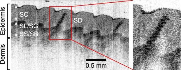
One frame from a 40 fps video sequence acquired using a swept-source OCT system with the self-starting, self-regulating FDML source. Skin layers comprising the epidermis (stratum corneum - SC, stratum lucidum - SL, stratum granulosum - SG, stratum spinosum - SS, stratum germinativum - SG), the dermis and sweat ducts (SD) can be observed.
4. Summary
In summary, we have demonstrated a self-starting, self-regulating FDML source. Our system is based on the hypothesis that the energy of the light traversing the FDML loop is maximized when the round-trip transit time and the filter sweep period are perfectly matched. To implement this scheme, we incorporated a feedback control system into the FDML loop. The control system consists of an energy detector to sense the energy and a VCO to drive the tunable filter. Without knowledge of the precise round-trip transit time, the system iteratively searches through a range of drive frequencies, while monitoring the energy till it is maximized. Subsequently, the system keeps track of the energy and adjusts the drive frequency to re-maximize it in case the energy reduces due to drift related desynchronization. The system allows accurate and repeatable startup in less than 5 seconds with no operator intervention and demonstrated reduced spectral fluctuations compared to a conventional FDML source. Real-time OCT imaging a fingertip (in vivo) with the SS-FDML source was demonstrated at 40,000 axial scans per second with an axial resolution of 8.9 µm, 7.5-dB roll-off over 2.3 mm and a detection sensitivity of over 120 dB.
Acknowledgments
This work was supported in part by the National Institutes of Health under grants R01CA120480 and R01EB007636.
References and links
- 1.de Boer J. F., Cense B., Park B. H., Pierce M. C., Tearney G. J., Bouma B. E., “Improved signal-to-noise ratio in spectral-domain compared with time-domain optical coherence tomography,” Opt. Lett. 28(21), 2067–2069 (2003). 10.1364/OL.28.002067 [DOI] [PubMed] [Google Scholar]
- 2.Leitgeb R., Hitzenberger C., Fercher A., “Performance of Fourier domain vs. time domain optical coherence tomography,” Opt. Express 11(8), 889–894 (2003). 10.1364/OE.11.000889 [DOI] [PubMed] [Google Scholar]
- 3.Choma M., Sarunic M., Yang C., Izatt J., “Sensitivity advantage of swept source and Fourier domain optical coherence tomography,” Opt. Express 11(18), 2183–2189 (2003). 10.1364/OE.11.002183 [DOI] [PubMed] [Google Scholar]
- 4.Chinn S. R., Swanson E. A., Fujimoto J. G., “Optical coherence tomography using a frequency-tunable optical source,” Opt. Lett. 22(5), 340–342 (1997). 10.1364/OL.22.000340 [DOI] [PubMed] [Google Scholar]
- 5.Golubovic B., Bouma B. E., Tearney G. J., Fujimoto J. G., “Optical frequency-domain reflectometry using rapid wavelength tuning of a Cr4+:forsterite laser,” Opt. Lett. 22(22), 1704–1706 (1997). 10.1364/OL.22.001704 [DOI] [PubMed] [Google Scholar]
- 6.Yun S., Tearney G., de Boer J., Iftimia N., Bouma B., “High-speed optical frequency-domain imaging,” Opt. Express 11(22), 2953–2963 (2003). 10.1364/OE.11.002953 [DOI] [PMC free article] [PubMed] [Google Scholar]
- 7.Yun S. H., Boudoux C., Tearney G. J., Bouma B. E., “High-speed wavelength-swept semiconductor laser with a polygon-scanner-based wavelength filter,” Opt. Lett. 28(20), 1981–1983 (2003). 10.1364/OL.28.001981 [DOI] [PubMed] [Google Scholar]
- 8.Huber R., Wojtkowski M., Fujimoto J. G., “Fourier Domain Mode Locking (FDML): A new laser operating regime and applications for optical coherence tomography,” Opt. Express 14(8), 3225–3237 (2006). 10.1364/OE.14.003225 [DOI] [PubMed] [Google Scholar]
- 9.Gora M., Karnowski K., Szkulmowski M., Kaluzny B. J., Huber R., Kowalczyk A., Wojtkowski M., “Ultra high-speed swept source OCT imaging of the anterior segment of human eye at 200 kHz with adjustable imaging range,” Opt. Express 17(17), 14880–14894 (2009). 10.1364/OE.17.014880 [DOI] [PubMed] [Google Scholar]
- 10.Potsaid B., Baumann B., Huang D., Barry S., Cable A. E., Schuman J. S., Duker J. S., Fujimoto J. G., “Ultrahigh speed 1050nm swept source/Fourier domain OCT retinal and anterior segment imaging at 100,000 to 400,000 axial scans per second,” Opt. Express 18(19), 20029–20048 (2010). 10.1364/OE.18.020029 [DOI] [PMC free article] [PubMed] [Google Scholar]
- 11.Wieser W., Biedermann B. R., Klein T., Eigenwillig C. M., Huber R., “Multi-megahertz OCT: High quality 3D imaging at 20 million A-scans and 4.5 GVoxels per second,” Opt. Express 18(14), 14685–14704 (2010). 10.1364/OE.18.014685 [DOI] [PubMed] [Google Scholar]
- 12.Klein T., Wieser W., Eigenwillig C. M., Biedermann B. R., Huber R., “Megahertz OCT for ultrawide-field retinal imaging with a 1050 nm Fourier domain mode-locked laser,” Opt. Express 19(4), 3044–3062 (2011). 10.1364/OE.19.003044 [DOI] [PubMed] [Google Scholar]
- 13.Xi J. F., Huo L., Li J. S., Li X. D., “Generic real-time uniform K-space sampling method for high-speed swept-source optical coherence tomography,” Opt. Express 18(9), 9511–9517 (2010). 10.1364/OE.18.009511 [DOI] [PMC free article] [PubMed] [Google Scholar]
- 14.Marschall S., Klein T., Wieser W., Biedermann B. R., Hsu K., Hansen K. P., Sumpf B., Hasler K. H., Erbert G., Jensen O. B., Pedersen C., Huber R., Andersen P. E., “Fourier domain mode-locked swept source at 1050 nm based on a tapered amplifier,” Opt. Express 18(15), 15820–15831 (2010). 10.1364/OE.18.015820 [DOI] [PubMed] [Google Scholar]


