Abstract
Compared with traditional open surgery, minimally invasive surgical procedures reduce patient trauma and recovery time, but the dexterity of the surgeon in laparoscopic surgery is reduced owing to the small incisions, long instruments and limited indirect visibility of the operative site inside the patient. Robotic surgical systems, teleoperated by surgeons from a master control console with joystick-type manipulation interfaces, have been commercially developed yet their adoption into standard practice may be limited owing to their size, complexity, cost and time-consuming setup, maintenance and sterilization procedures. The goal of our research is to improve the effectiveness of robot-assisted surgery by developing much smaller, simpler, modular, teleoperated robotic manipulator systems for minimally invasive surgery.
Keywords: robotic surgery, minimally invasive surgery, laparascopy, teleoperation
1. Introduction
Robot-assisted minimally invasive surgery (MIS) can eliminate manual tremor, introduce scaling factors between the hand motions of the surgeon and the robotic instruments, and provide additional articulated joints at the tips of the instruments, resulting in enhanced surgical dexterity which may lead to improved patient outcomes and make more difficult procedures feasible. The development and validation testing of a simpler, compact, portable, robotic surgery system with equivalent performance, greater ease of use, more versatility and reduced setup time compared with existing commercial robotic surgery systems would increase the availability of robotic assistance in standard operating rooms and for more surgical procedures.
Although several robot-assisted MIS systems have undergone favorable clinical validation trials, have obtained regulatory approvals and have been made commercially available, their actual use is rare compared with standard procedures and their adoption has been limited and gradual. The cost, complexity and size of these robotic systems and their required setup time and maintenance cause them to be difficult to be integrated into typical operating rooms. These current surgical robots are similar to industrial serial-link robot arms, whereas smaller, more specialized but less-complex designs would be better suited to a human environment such as the operating room.
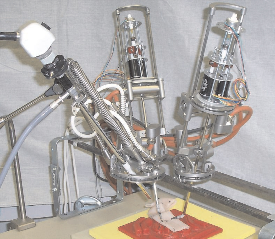
The manipulators of our teleoperated system for robotassisted MIS are pictured in Figure 1. One endoscope manipulator and two instrument manipulators are individually clamped to a rigid frame which is mounted to both sides of the operating table above the patient so that the manipulator bases encircle the insertion points of the endoscope and instruments in the abdominal wall of the patient. The size, mass and cost of our robotic teleoperated surgery system is one to two orders of magnitude less than those of current typical commercial systems.
Fig. 1.
Teleoperated surgical system manipulators and instruments.
More detailed background of robot-assisted MIS systems is given in the following section. Section 3 describes the general configuration of our newly developed teleoperated robotic MIS system, Section 4 describes the endoscope manipulator, Section 5 describes the instrument manipulators, Section 6 presents preliminary user teleoperation studies, and Section 7 concludes the paper.
2. Background
Medical robots are currently an active field of research and development. A survey from 2003 (Taylor and Stoianovici 2003) lists 169 references describing 21 systems for surgical planning and execution or “CAD/CAM” systems and 15 surgical assistant systems, in medical areas including needle guidance, imaging and orthopedic, neuro, cardiac and abdominal surgery. Another survey (Pott et al. 2004) mentions 84 different medical robot systems in categories of general surgery, orthopedics, imaging, neurosurgery, oral/maxillofacial/ear–nose– throat surgery, urology, trauma and radiological surgery, although only 23% of these systems have been tested on patients and 14% have been made commercially available. Adoption of robotic devices in standard medical procedures has remained rare until the present due to reasons that may include difficulties of integrating robots into the operating room, safety concerns, high costs and the lack of proven quantitative benefits from robotically assisted procedures.
It is often advantageous in robot-assisted surgery to use manipulators which can rotate an instrument about a fixed pivot point which can be external to the manipulator, using a subset of the total number of joint actuators available. Manipulators with this type of remote center of motion can be realized using a parallelogram or other type of parallel linkage configuration, passive joints, spherical joints or with pivoting rings and goniometers. Examples of surgical manipulators with each of these remote center of motion architectures are described in the following sections.
Various robotic systems have previously been developed to assist surgeons in performing minimally invasive laparoscopic surgical procedures, either as a standalone robotic endoscope manipulator (Taylor et al. 1995; Kobayashi et al. 1999; Buess et al. 2000; Munoz et al. 2000) or a complete teleoperated robotic surgery system with multiple manipulator arms for instruments. These robots generally consist of a large, heavy base and serial or parallel linkage arms to hold the endoscope or manipulate an instrument. The AESOP from Computer Motion Inc., (Sackier and Wang 1995; Geis et al. 1996), LapMan from Medsys S.A. (Polet and Donnez 2004) and EndoAssist from Armstrong Healthcare LLC (Finlay 1996) are examples of commercial endoscope manipulators that have undergone clinical validation studies and have obtained various regulatory approvals. In addition, minimally invasive complete telerobotic surgical systems include the da Vinci from Intuitive Surgical Systems (Guthart and Salisbury 2000) and Zeus (Reichenspurner et al. 1999) system from Computer Motion. The AESOP and Zeus systems are no longer commercially available however, as Computer Motion was absorbed by Intuitive Surgical Systems.
2.1. Endoscope Manipulators
AESOP is a four-degree-of-freedom (DOF) robot endoscope manipulator with a SCARA-type (Makino and Furuya 1982) articulated serial link architecture. The wrist of the robot contains a two-DOF passive gimbal joint where the endoscope is held. The base of the robot is clamped to a rail on the side of the operating table. The robot must be draped in sterile plastic during surgery. Minimum height limits must be set before use, but no other calibration or registration procedure is necessary. The endoscope is held by a magnetic clamp which releases if external forces or torques are too large. The last AESOP 3000 model was provided with a voice control system to command motion in all directions, variable speeds and preset positions. Earlier control systems used pedals.
Various clinical trials have been performed with AESOP (Kavoussi et al. 1995; Mettler et al. 1998). A study of 26 laparoscopic cholecystectomies performed with either AESOP or a human assistant showed no significant difference in duration of patient stay or postoperative complications, and surgeons preferred the stability of the image of the robot supported endoscope (Geis et al. 1996). The average operative time required was 235 minutes with a human assistant and 213 minutes with AESOP.
EndoAssist (Aiono et al. 2002) is a floor-standing robot designed as an endoscope manipulator surgical assistant. It consists of an articulated arm and a wheeled base. The robot base is 520 mm wide, 812 mm deep and extends from 1,470 to 2,170 mm high. EndoAssist has four actuated joints that correspond to the DOFs of the endoscope, and a passive pin joint where the endoscope is attached. The kinematics of this joint configuration produce a remote center of motion pivot point which must be manually aligned with the incision point of the trocar by rolling the robot base to the correct location and adjusting the height of the vertical axis. Two laser diode spots on the robot aid the manual registration of the pivot point at the incision. The end of the manipulator arm is detachable and autoclavable, and the arm itself must be enclosed in a sterile bag or drapes during surgery. In general, the arm holding the endoscope is sufficiently long and high that it does not interfere with the surgeon’s instruments, but a curved arm is also available for use in those cases where the straight arm impedes the free motion of the instruments. The developers claim that a freestanding robot with a wheeled base is easier to set up than a robot mounted on the operating table.
The surgeon controls the movement of the EndoAssist manipulator by motions of the head. A headband must be worn with transmitters which are localized by a receiver by the video monitor. The robot only responds to head-movement commands while a footswitch is depressed. For safety, the end-effector contains a force sensor and the robot is stopped if the force on the endoscope exceeds a given threshold. The passive pin joint and the configuration of the active joints constrain the endoscope to pass through the incision point even in the case of joint failure. Stepper motors with redundant encoders are used to minimize the possibility of uncommanded motion errors.
Clinical evaluation of EndoAssist (Aiono et al. 2002) was performed in a randomized series of 100 laparoscopic cholecystectomies. Procedures undertaken with manually held endoscopes required an average of 75 minutes, while procedures using EndoAssist required 66 minutes, resulting in a time saving of 9 minutes (or 10%). The standard deviation of the procedure time was also reduced from 22 to 16 minutes.
The LapMan (Polet and Donnez 2004) from Medsys S.A. is another commercially available endoscope manipulator for laparoscopic surgery with CE and FDA certifications. Its base rests on the floor and the endoscope is supported by an articulated robotic arm which extends across the patient. User control is provided by a small keypad held in the palm of the surgeon or a small joystick attached to one of the surgical instruments. A calibration period using a laser pointer is necessary to position the pivot point of the robot at the entry port incision of the endoscope.
2.2. Teleoperated Robotic Systems for MIS
The Zeus (Butner et al. 2002) teleoperation master console consists of a video screen, two passive, counterweighted control arms and a voice-controlled system to generate motion commands to control the position and orientation of the endoscope manipulator. The manipulator system includes three serial-link arms which are mounted at their bases to the sides of the operating table. The endoscope and instruments are attached to the manipulators through passive gimbals which allow each instrument to pass through and pivot about its incision point as the distal end of each instrument is moved by its manipulator. Magnetic force-limiting breakaway mounts release the instruments in the case of any collision or obstruction of the instruments. A Zeus system was used in 2001 to perform a cholecystectomy on a patient in Strasbourg, France by a surgeon in New York (Marescaux et al. 2001; Butner et al. 2002).
The da Vinci system (Guthart and Salisbury 2000) was developed by Intuitive Surgical Inc. and is currently commercially available. The da Vinci teleoperation console is partially enclosed and includes a stereoscopic display for three-dimensional visualization. The manipulator arms incorporate parallelogram-type kinematic linkages (Madhani 1998) in order to conform to the motion constraints imposed by the fixed incision point of each instrument. The system can be used for a variety of difficult surgical procedures such as minimally invasive coronary artery bypass grafts (Loulmet et al. 1999; Falk et al. 2000; Kappert et al. 2000).
In conventional laparoscopic surgery, long, thin surgical instruments are introduced into the body of the patient through small “keyhole” incisions, resulting in a reversal between the motion directions of the instrument handle and tip due to the pivot point at the incision. This reversal adds to the difficulty of performing manual laparoscopic surgery. Our teleoperated robotic laparoscopic surgery system and the systems referenced here correct this motion reversal by using the motions of the teleoperation master to control the motions of the surgical instrument tips directly, rather than controlling the motions of a virtual instrument handle with reversed motion directions.
The Zeus and da Vinci systems use surgical instruments with additional actuated articulated joints near the tips of the instruments, whereas standard MIS instruments have straight, rigid shafts. These articulated joints or wrists allow the surgeon to arbitrarily orient the working ends of the robotic instruments during surgery, which increases dexterity by enabling the instrument tips to grasp or cut in a wide range of directions rather than remaining aligned with the instrument shaft. One disadvantage of current teleoperated robotic surgical systems is that the surgeon cannot feel the resistance of contacts between the instrument tips and the tissues of the patient. Force sensing at the instrument tips and force feedback applied at the teleoperation console could remedy this potential drawback, but it is difficult to accurately sense forces at the instrument tips owing to their small size and the harsh environments to which they are subjected inside the patient. Nevertheless the development and study of haptic (force and tactile) feedback in teleoperated surgery is a topic of active research (Kitagawa et al. 2002; Berkelman et al. 2003b; Tavakoli et al. 2003).
Although current minimally invasive surgical systems perform well, they resemble industrial robots and are correspondingly large, heavy, complex and expensive. In the limited space of a typical crowded operating room, these robotic systems occupy a considerable amount of space next to the patient and require regular maintenance and time-consuming initialization and setup procedures prior to each surgical procedure. We believe that these are the major obstacles currently limiting the adoption of teleoperated manipulators in surgery.
A more recent approach in medical robotic systems is to use smaller, simpler robots which can be directly attached to or fully or partially supported by the body of the patient. A survey of five representative systems (Berkelman et al. 2004) includes applications in hip and knee arthroplasty, orthopedic screw placement and drill guiding, remote ultrasound evaluations through teleoperation and endoscope positioning in MIS. Body-supported medical robots rest upon the patient’s body and can be designed to be much more compact and lightweight, leading to improved accuracy and safety and reduced cost, and they are easier to set up and use in the operating room environment compared with conventional robot manipulator arms.
Lum et al. (2006) at the University of Washington have also developed the RAVEN teleoperated robotic MIS system which is more compact than currently available systems. The manipulators of this system are based on spherical joint kinematics where all joint axes intersect at the incision points. Although their system is much smaller than the current commercial systems and can be attached to the sides of an operating table, they still have important drawbacks: the manipulators nevertheless occupy a large volume above and to the sides of the patient; at 10 kg they are too massive to be easily portable; and they are not sterilizable. Our proposed system described in the following section overcomes these drawbacks.
The Laprotek system (Franzino 2003; Coa and Rogers 2004) developed by endoVia Medical, Inc. is another robotic surgical system which was developed to be smaller, less costly and easier to use than current systems. It is reported to be capable of force feedback and its instrument manipulators are also clamped to the sides of the table and positioned above the patient; however, it is not autoclavable and must be draped in sterile sheeting, and its cable drive, greater mechanical complexity and greater mass compared with our system cause it to be somewhat more cumbersome and results in degraded precision.
Although other research groups have pursued the idea of developing surgical robot systems which are smaller and easier to use than current systems, our approach is unique in that the manipulators are to be less than 2 kg each, autoclavable and waterproof so that they may be treated as any other piece of surgical equipment in the operating room, without requiring any additional procedures for initialization or sterilization before or after a surgical procedure.
3. Compact Modular System Configuration
Our design approach in the development of our teleoperated robotic surgery system has been to combine simple, modular components which can be easily set up and operated and do not require any special preparation other than clamping them in place and standard operating room sterilization and cleaning procedures. The individual manipulators are less than 2 kg each so that they are portable and can be lifted easily and positioned by hand in a desired location above the abdomen of the patient. The endoscope and instrument manipulators are each clamped to a rigid frame in their desired positions for the surgical procedure, and the frame is fixed to the rails of the operating table on either side. Quick-release clamps are used to attach the manipulator bases to the frame and the endoscope and instruments to the manipulators, so that any component of the system can be added, removed, repositioned or exchanged at any time with one hand during any surgical procedure. Furthermore, all system components within the operative field are sterilizable by autoclave and are water resistant for cleaning by immersion. The remaining system components and methods for teleoperation control are selected to be simple and robust. To maximize the safety, reliability and accuracy of the entire system, the top design priorities have been simplicity and modularity: each hardware component operates independently and can be replaced at any time without disturbing the operation of other components, the number of moving parts has been minimized and software tasks execute in separate threads.
The only constraint on the positioning of the tool port incisions in our system is that they must be separated by 80 mm, owing to the diameters of the instrument manipulator base rings. As there are no additional robotic arm link structures above or next to the manipulator mechanisms shown in Figure 1, the manipulators cannot collide or interfere with each other provided that the instruments and endoscope are all pointed towards a common area of interest. With the da Vinci system, some preplanning is necessary to find a set of manipulator support arm configurations which will not result in collisions during a procedure (Adhami and Coste-Manière 2002, 2003).
3.1. System Overview
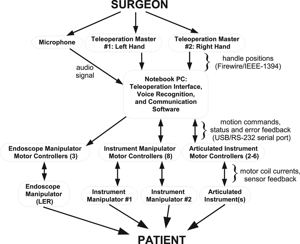
Figure 2 shows the overview of the compact laparoscopic surgery robot system. The components of the complete surgery robot system include the following.
Fig. 2.
Components of teleoperated surgical system.
Teleoperation masters. The masters sense the surgeon’s hand motions and transform these motions into position signals.
Instrument manipulators. The instrument manipulator follows the master motion command signals to control the translational and rotational motions of the surgical instruments attached to the manipulators.
Endoscope manipulator. The structure of the endoscope manipulator is similar to the instrument manipulators except for its lower force/torque requirement for moving the endoscope and one fewer DOF. The endoscope manipulator can move according to voice commands of the surgeon or semi-autonomously to track the object in the surgical site from the endoscope video images (Voros et al. 2006).
Motor controllers. Motor controllers are used to drive the DC brushless motors in the manipulator and the linear actuator motors in the surgical instrument.
Surgical instruments. According to different surgical tasks, different surgical instruments such as grippers and scissors are installed in the instrument manipulators.
Video feedback. The video signal is acquired from the endoscope and the video feedback is provided by a monitor for the surgeon and nurses to observe the surgical site.
Voice command. Since the surgeon’s hands are occupied by two masters, the voice command system is used to control the endoscope manipulator.
Control software. The control software includes hardware device drivers, master–slave control, the human– machine interface and other tasks.
3.2. Master Console
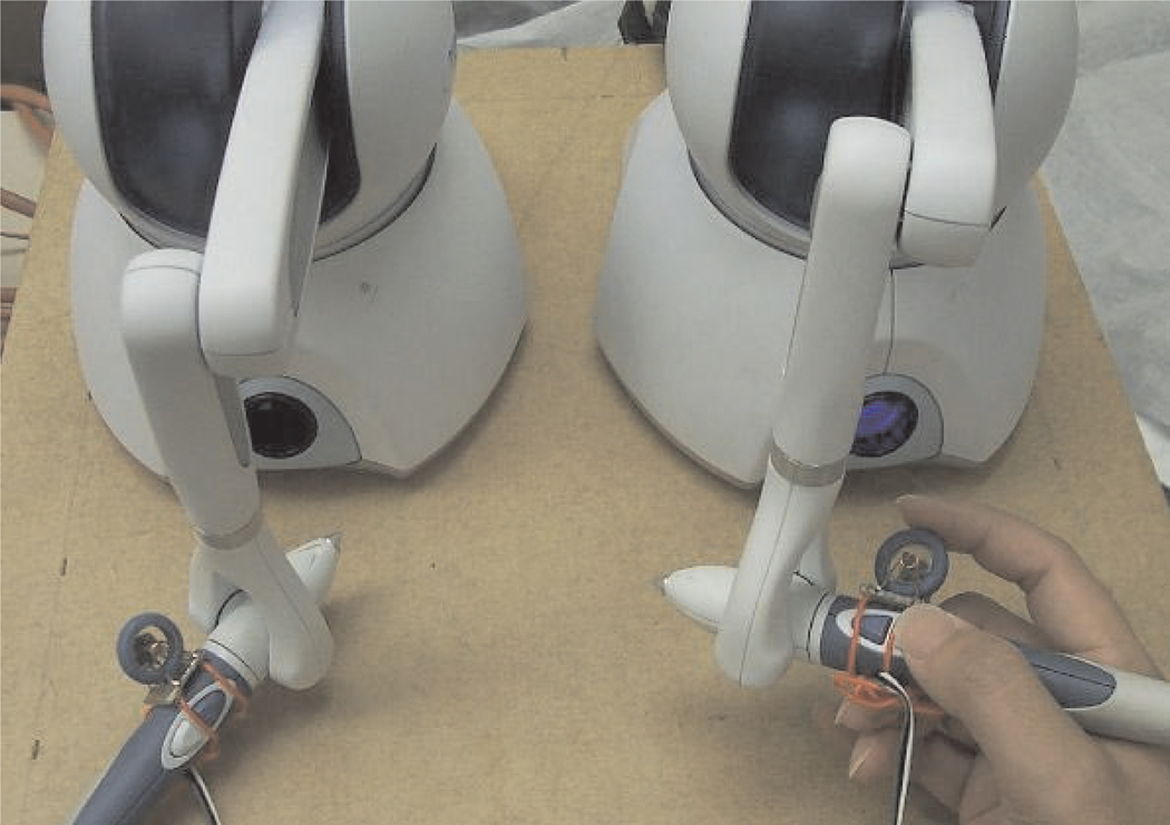
Two commercial haptic devices (Phantom Omni, Sensable Technology, Woburn, MA) (Massie and Salisbury 1994) are used in the master control console for teleoperation of the surgical instrument manipulators. Each of the master controllers can sense three DOFs of position information in Cartesian space, three DOFs of rotation information and can provide three DOFs of force output to the user. In the current prototype, the force output is not provided owing to the absence of force sensors in the manipulators. Force feedback can easily be added to the system if force sensing of adequate quality can be developed for the surgical instruments.
For easy and comfortable operation, the operator can select the zero position offset, orientation and scaling factor of the haptic device coordinate frame relative to the controlled manipulator. One of the buttons on each haptic device handle stops the motion commands sent to the instrument manipulators from the haptic devices to allow repositioning of the master devices relative to the manipulator positions.
As the kinematic configuration of the haptic device controllers in the master console do not match the instrument manipulators, the joint values of the haptic device are converted to Cartesian coordinates, then to joint space coordinates to generate motion command setpoints for the instrument manipulators. The inverse kinematics calculations to calculate the Cartesian setpoints are performed by the haptic device software libraries. The forward kinematics calculation of the instrument manipulator joint values is equivalent to conversion from x,y,z Cartesian coordinates to θ, φ, ρ spherical coordinates.
In the initial experiments, the two buttons on the handle of the haptic device were used to open and close the gripper. However, it was found that the forces required to press the buttons induced motions in the system. Furthermore, the gripper opening and closing is difficult to control precisely using on/off buttons. Therefore, instead of using the buttons for gripper control, a mouse scrollwheel and encoder were attached to the handle of the haptic device as shown in Figure 3. The encoder signal is detected by a microcontroller which directly controls the linear actuator driver board to control the gripper opening and closing. Owing to the limited accuracy of the encoder, the gripper opening range is about 10 steps which realizes the quasi-continuous opening and closing of the gripper. Although the present encoder has limited precision for gripper control, it is an improvement compared with the on/off buttons on the handle for gripper control. An improved gripper controller is currently in development which uses a linear potentiometer instead of an encoder to more precisely sense the gripping motions of the teleoperation masters.
Fig. 3.
Master console for teleoperation.
3.3. Software Communication and Control
A compact touchscreen PC console is used for high-level control of the system. The PC communicates with each motor controller over a separate RS-232 serial port connection to maximize the communication throughput to each controller. The high-level software architecture and approach for control and user interaction are described in further detail by Ma and Berkelman (2006).
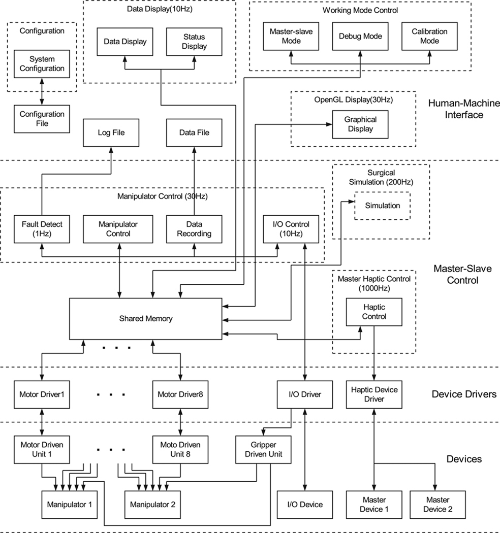
For the requirements of real-time operation, reliability, ease of operation and upgradeability, the software is designed with multi-threaded, multi-priority and modularized concepts. In the future, the software can be implemented using embedded real-time operation systems for more reliable operation. The software architecture is shown in Figure 4. It consists of three layers: hardware device drivers, master–slave control and a user interface. The device drivers have the highest priorities in the software system for the requirement of real-time control of the hardware. The master–slave control task has high priority to calculate the master–slave control variables and the human–machine interface software has normal priority.
Fig. 4.
Control software architecture.
Device drivers are used to interface with the hardware by decoding the signals from the hardware devices into values which can be used by the master–slave control software, and encoding the control values and commands into signals to send to the hardware devices. The device drivers include motor drivers which communicate with the motor driven units, input/output drivers which control the digital input and output signals, and master haptic device drivers. Except for the haptic device drivers which are provided, the other drivers were programmed by the authors. These device drivers run at the highest priority in the system to assure real-time hardware control. The modular structure of the device drivers makes the software expandable and easy to maintain. If any of the hardware devices are changed, only the corresponding hardware drivers need to be changed without revising all of the code.
The master–slave teleoperation control software includes a manipulator motion control module, a haptic device control module, a data-logging module and an error-detection module. The control rate of each module depends on the time criticality of its associated tasks. For example, the control rate of the haptic devices is faster to smoothly sense the motions of the user, and the control rate for error detection is the slowest. The control rate for the manipulator motion control is limited by the maximum communication bandwidth between the computer and the motor driver units. The control frequencies of the different software modules are given in Table 1.
Table 1.
Control frequencies of the different software modules.
| Software module | Frequency (Hz) |
|---|---|
| Manipulator motion control | 100 |
| Error detection module | 1 |
| I/O control module | 10 |
| Haptic device control | 1,000 |
| Surgical simulation | 200 |
At present, the haptic device control module is only used to obtain the operator’s hand motion information, there is no force output to the operator. The haptic output function is inactive due to the absence of force sensor in the slave. The surgical simulation module is reserved for future development to provide virtual 3D training for the surgeons and help them operate the robot system skillfully and quickly.
The motions of the slave manipulators are realized by controlling the manipulator motors to move according to the target positions from the master devices operated by the surgeon. Figure 5 shows the diagram of the joint position closed-loop control for each joint. The input is the given joint position which is calculated from the master’s given position by using inverse kinematics. The feedback joint position is measured and decoded from the Hall sensor in the motor by the motor controller. The current position control law is a proportional-plus-derivative control algorithm (PD). The input of the PD controller is the joint angle error and the output is the velocity control code to each motor controller. The motor driven unit adjusts the motor velocity according to the output control code.
Fig. 5.
Joint position control for teleoperated instrument manipulators.
3.4. Actuation
Miniature brushless DC motors and motor controllers (MicroMo/Faulhaber) are used for each DOF in the manipulators with the exception of the gripper action, which is controlled by a linear step motor. The motor motions can be controlled in either position or velocity modes. The brushless motors are certified to withstand the high pressures and temperatures of autoclave sterilization for at least 100 cycles. Sinusoidal Hall effect sensors are integrated into the brushless motors both for commutation and servo control, as standard motor shaft encoders do not allow autoclave sterilization. Owing to the small size and mass of the endoscope and instrument manipulators, 16 mm and 20 mm gearmotors at 100 g or less provide sufficient torques and speeds. The small motors and low mass of the manipulators provide an intrinsic safety benefit of the system compared with large robotic arms, as the motor torques and kinetic energies generated during operation are much lower and less likely to cause any trauma to patient anatomy in the case of accidental collision. Compact single-axis controllers (MCBL 2805, Faulhaber) provide proportional–integral (PI) error feedback control of the brushless motors with Hall effect sensor feedback. The motor controllers are programmed to operate in position control mode to accurately hold a desired position and switch to velocity control mode when motion commands are given. Input and control gains, minimum and maximum speeds, maximum currents and other controller parameters are fully configurable and can be written to the motor controller electrically erasable programmable read-only memory (EEPROM). In practice, the maximum currents of the motors can be set by the motor controllers to a level which is sufficient for the surgical procedure to be performed but no greater, so as to minimize the risk of danger owing to uncontrolled collisions with patient anatomy. The maximum force that can be applied to patient anatomy without injury is, however, highly dependent on the geometry of the instrument and tissue, as virtually imperceptible contact forces may be fatal if a vessel is cut for example.
Velocity control is used during manipulator motions for improved response and safety: if position control alone is used, then manipulator motion may continue to correct for position errors after the master controllers have stopped moving, creating a safety hazard and the perception of lag by the operator. Position control is used while the manipulators are stationary to prevent any drift which can occur from velocity control.
4. Endoscope Manipulator
Our teleoperated system for MIS uses an endoscope manipulator which may also be used in a standalone mode for use with manually operated surgical instruments. Prior versions of the endoscope manipulator used in our system are described by Berkelman et al. (2005) and Long et al. (2007) as the LER (Light Endoscope Robot). The latest version is undergoing in vivo testing to be made available commercially as the ViKY (Long et al. 2007).
The LER (Berkelman et al. 2003a) is a compact surgical assistant robot for positioning of an endoscope and camera during MIS. In contrast to typical endoscope manipulators, the LER is particularly compact and lightweight at 0.6 kg and 11 cm in diameter (comparable in size and weight to a coffee mug), so that it is simple to set up and use, occupies no floor space and does not limit access to the patient in any way. It features a full motion range of 360° in rotation, and a range of inclination from vertical to 10° from horizontal. Backdrivable motors allow the robot to be repositioned manually at any time by switching off the motor currents, such as during initial setup or in the case of component failure. Motor currents and actuation forces are limited for safety. The LER is typically clamped to the side of the operating table by a rigid arm, but it may also be held in place on the abdomen by adhesive strips, sutures or elastic straps. A variety of different user command interfaces have been implemented for LER, including a miniature keypad, automatic optical instrument motion tracking and voice command recognition.
4.1. Design
The torque requirements of the LER were determined by the maximum expected mass and horizontal extension of the endoscope camera. The range of motion was selected from observation of several minimally invasive surgical procedures and discussion with digestive and urological surgeons. The required joint velocities were selected so that the range of motion in any direction could be traversed in 5 seconds; these velocities were reduced at the request of surgeons after undergoing trials on cadavers and animals. Owing to the large field of vision of the endoscope optics, position and orientation accuracies of 1 mm and 1° were taken to be sufficient.
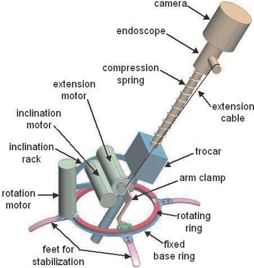
A schematic model of the LER is shown in Figure 6. The LER consists of an annular base placed on the abdomen, a clamp to hold the endoscope trocar, and two joints which enable azimuth rotation and inclination of the endoscope about a pivot point at the incision. A compression spring around the endoscope shaft and a cable wrapped around a motorized spool control the insertion depth of the endoscope. Control of the robot is simple and straightforward, as the motion of each motor directly corresponds to the horizontal and vertical motion and zoom of the endoscope camera image. As a result, no kinematic calculations, initialization procedures, or homing sequences need to be performed to operate the robot. No calibration is necessary and the LER is ready to be used immediately after being powered on. The robot is fully sterilizable; plastic draping for sterility is unnecessary and all components can withstand multiple standard autoclave cycles. The robot base is wide enough to pass over standard endoscope trocars and the robot may be removed while leaving the trocar in the patient. The trocar clamp accommodates trocars up to 12 mm in diameter.
Fig. 6.
Schematic model of the endoscope manipulator.
4.2. Development for Clinical Use
The endoscope manipulator was designed to be sterilizable by autoclave to eliminate the need for sterile drapes typical of large medical robot systems. This serves to simplify and reduce the time required to set up the system, and eliminates the risk of contamination owing to torn or misplaced drapes and the cost of custom formed disposable drapes. The motors, reducers and connectors in the manipulator are certified by the suppliers to be autoclavable, all wiring connections and cabling are sealed in silicon materials, and the mechanism parts are fabricated from stainless steel and hard anodized aluminum materials which resist corrosion and surface degradation from repeated autoclave cycles.
Owing to increasing concerns in Europe regarding prion diseases such as Creutzfeldt–Jakob disease, current sterilization protocols there require that surgical instruments must be immersed in a caustic solution for 20–30 minutes in addition to the autoclave cycle. This requires the LER motors to be watertight as well as autoclavable so that the internal wiring and electronics of the motors are not damaged by leakage of the caustic solution. Waterproof seals were added to the output shafts of the motors in response to this change in sterilization protocols.
4.3. Motion Command Interfaces
An effective user command interface for the light endoscope robot should enable the surgeon to reposition the endoscope without any assistance and without releasing either of the instruments held in each hand. We have aimed to provide a variety of different command interface methods for surgeons to select from according to their own requirements and preferences. The motor drives were selected to be backdrivable so that the endoscope may be positioned by hand when the motor currents are switched off. Manual positioning of the robot is direct, simple and intuitive, and is the easiest means for initial positioning of the robot before other instruments are introduced into the abdomen and while the surgeon has at least one hand free. Advances in voice recognition software technology and PC computational power have made a voice command interface fairly straightforward, although some training of both the system and the users is necessary for the best reliability. We have implemented a standard voice recognition system with a vocabulary of 14 two-word motion commands. A set of footswitches is also provided to control the motion of the endoscope manipulator, and an automatic instrument tracking and following software system is in development which uses machine vision and geometric information (Voros et al. 2006).
4.4. Trials and Commercialization
Trials of the endoscope manipulator with manual instruments were initially undertaken on cadavers and pigs (Berkelman et al. 2005) and continued throughout its development (Long et al. 2007). The current version has obtained CE marking for sale in Europe and further development and commercialization are in progress by Endocontrol SA, of Grenoble, France. Human trials in vivo are currently in progress for several different procedures at 17 hospitals in seven countries.
4.5. Parameters
The most important parameters of the endoscope manipulator are given in Table 2.
Table 2.
The most important parameters of the endoscope manipulator.
| Parameter | Value | |
|---|---|---|
| Mass | Manipulator | 625 g |
| Endoscope and camera | 300–500 g typical | |
| Backdrivability | Torque | 0.45 Nm |
| Force on endoscope tip | 1.5 N | |
| Dimensions | Height | 75 mm |
| Diameter | 110 mm | |
| Motion range | Azimuth rotation | 360° continuous |
| Inclination | 80° from vertical | |
| Extension | 160 mm | |
| Maximum speed | Azimuth rotation | 20° per second |
| Inclination | 20° per second | |
| Extension | 25 mm per second | |
| Maximum torque Limit | 6 Nm | |
| Maximum force | 20 N | |
| Actuation hysteresis | 0.38° maximum |
5. Instrument Manipulators
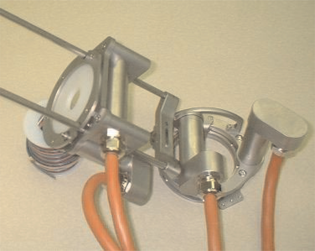
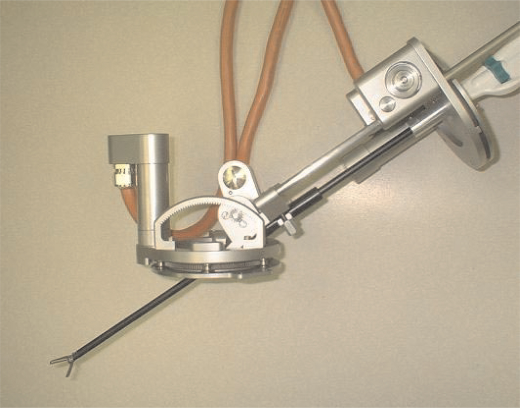
The basic structure and design of the instrument manipulators in the system are similar to the endoscope manipulator described in the previous section. The principal difference present in the instrument manipulators is that the additional DOF of the rotation of the instrument shaft must also be controlled. This fourth DOF is not necessary in the endoscope manipulator because the vertical axis of the endoscope camera image automatically remains aligned with the vertical direction inside the abdomen. A single instrument manipulator is shown in Figures 7 and 8.
Fig. 7.
Instrument manipulator robot prototype.
Fig. 8.
Instrument manipulator robot holding manual surgical instrument.
5.1. Base
The pivoting ring on the base of the manipulator is supported by pinions rather than bearings for hygiene and ease of cleaning. An annular base enables azimuth rotation and a pivoting arm enables inclination of a surgical instrument inserted through a trocar sleeve which is clamped to the robot. Both rotations pivot about the central point of the robot base, which is aligned with the incision point during use in MIS. The base of the instrument manipulators is smaller in diameter than the endoscope manipulator in order to more easily place multiple robots next to each other on the abdomen of the patient.
5.2. Instrument Holder Platform
The minimally invasive surgical instruments are attached to an upper platform which moves along a rack-and-pinion mechanism to control the insertion depth of the instruments into the abdomen. The rack-and-pinion is used instead of the cable-and-spring mechanism of the endoscope manipulator owing to the greater precision and forces required in the instrument manipulators. The rack-and-pinion motor and a fourth motor to rotate the instrument shaft are both built into the upper platform. We used 16 mm diameter brushless motors instead of 20 mm motors to reduce the weight and size of the upper platform. Quick-release clamps hold the surgical instruments so that the instruments can be exchanged quickly and easily during surgical procedures.
6. Articulated Wrists
We have produced instruments with articulated, motorized wrists at the active ends to improve surgical dexterity compared with standard manual instruments in MIS. The ability to bend an instrument tip up to 90° in any direction, teleoperated from the master console, enables the tip to approach and contact tissues from a wide range of angles, can avoid occlusions and obstructions, and provides better access for gripping and cutting, and especially suturing, in which the tip of a needle must follow a helical path. The addition of these articulated wrists to our system provides the full teleoperated robotic surgical assistance functionality equivalent to current commercial systems. Although the current prototype instrument wrists in development have not yet been tested to withstand repeated autoclave cycles, all of the motors and materials used in the instrument wrists are commercially available in autoclavable versions. Alternatively, it may be advantageous in terms of hygiene, time and cost to produce the articulated wrists and instrument end effectors to be single-use only, disposable and detachable from the autoclavable motors and sensors.
6.1. Wrist and Gripper
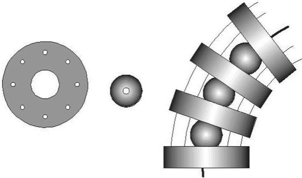
The articulation of the wrists was realized using an assembly of ball joints, plates and wires for actuation, as shown in Figure 9. This mechanism is similar to one described by Van Meer et al. (2005) and has been found to be much easier to fabricate than mechanisms with a combination of miniature joints and pulleys. The wrists provide two additional DOFs to each surgical instrument.
Fig. 9.
Plates and spheres with the wires-in-wrist assembly.
Four wrist plates (1.8 mm height and 6 mm diameter) and three spheres (3 mm diameter) of PEEK plastic are stacked together with each sphere between two plates. The wrist plates have drilled holes for eight superelastic Nitinol alloy wires (0.33 mm diameter) to pass through. Four wires are used to actuate the wrist rotations and the other four are passive to provide the wrist more axial rigidity. The spheres are pierced to guide the tool tip actuation wire.
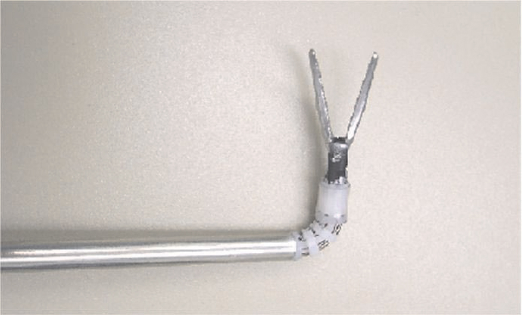
Figure 10 shows the wrist with an attached gripper. The length of the flexible part of the wrist is 12 mm. A conventional manual surgical tool tip (5 mm diameter) is attached at the end of the wrist. The opening and closing of the gripper is driven by another Nitinol wire (0.43 mm diameter) which passes through the pierced spheres and wrist plates and is controlled by a linear actuator.
Fig. 10.
Surgical instrument wrist with gripper.
6.2. Wrist Actuation
To integrate the surgical wrist in the compact surgical robot manipulator, the wrist wires are driven by electric motors. Each pair of antagonistic Nitinol wires in the wrist is driven by a brushless DC motor through a miniature gearbox and pulley. The wire tension can be adjusted with screws to change positions of both motor and the length of each driving wire.
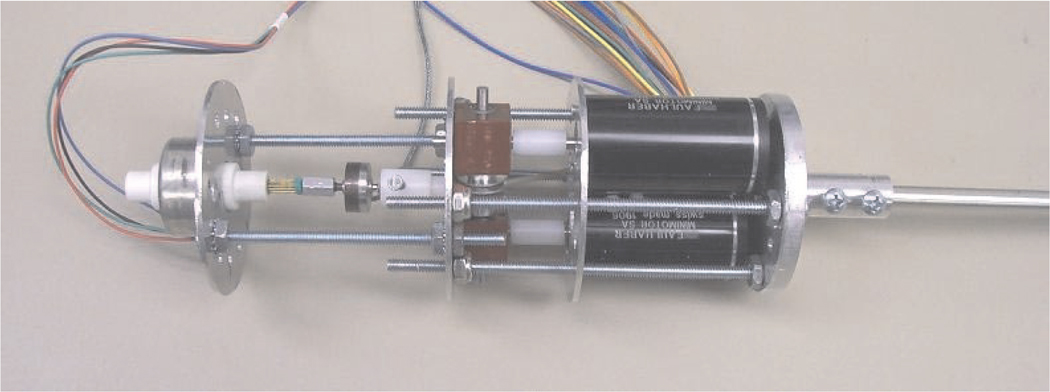
Figure 11 shows the components and assembly of the motors to drive the wrist and instrument tool tip. The wrist motor structure is designed to be lightweight, compact and modular to allow easy installation and exchange of instruments on the surgical manipulators during surgical procedures. The motor structure is 55 mm in diameter and 170 mm in length. The total length of the modular surgical instrument prototype is 450 mm and its mass is 380 g.
Fig. 11.
Actuation motor assembly.
In order to measure the tissue grasping force applied by gripper, a miniature load sensor is installed between the gripper driving wire and the gripper driving linear actuator. The grasping force in the gripper can be sensed from the measured force in the gripper driving wire. Figure 12 is a diagram of one modular motorized surgical instrument.
Fig. 12.
Surgical instrument with articulated wrist.
6.3. Performance Parameters
The experimental results show that the wrist bending motion ranges are 90° in all directions. The maximum dynamic force generated in the end of the wrist is approximately 5 N. The measured maximum tension in the gripper actuation wire is approximately 15 N. A larger grasping force can easily be achieved by using a larger force output linear actuator as needed.
7. User Testing
In order to compare the performance of our surgical robotic system with typical manual MIS instrument operation, user testing experiments were designed and performed (Ma and Berkelman 2007). Two tasks were performed by participants using both the manual MIS instrument and the teleoperated robotic system. An optical motion capture system (Optotrak, Northern Digital Inc.) was used to capture the motions of the surgical instrument tips for both the manual and the robot task operations. All tasks are performed using one hand. Two typical manually operated gripper instruments for MIS procedures were used in the experiments, with one instrument for manual operation and the other fixed in an instrument manipulator for robotic teleoperation. For these initial user trials with simple positioning tasks and untrained operators, the articulated instrument wrists described in Section 6 were not used, to simplify the teleoperation interface and reduce the training and familiarization period for the operators. Our initial user studies have focused on effective teleoperation performance by untrained subjects in general tasks. As the details of the system hardware, software and control system are further refined we will proceed to user studies of trained surgeons performing realistic models of surgical procedures.
Four infrared LEDs were affixed to the handle of each surgical instrument to enable tracking of the instrument tip position at a 30 Hz sample rate. This motion tracking technique accounts for all motion from hysteresis, vibration and deformation in the manipulator support clamps, support frame and mechanism, except for flexing of the instrument shaft between the handle and tip. In order to simulate a realistic MIS environment, the two-dimensional video camera and TV monitor were used as the visual feedback for the participants. All experiments required the participants to stand for operation.
7.1. Participants
Eleven participants, ten novices and one author, were asked to perform the two experiments. The novice participants had no prior experience in manual or teleoperated MIS operation while the author had experience on both systems. Ten participants were right-handed and one was left-handed. They all performed the tasks with their right hands.
Before the experiments, each participant was allowed 2– 15 minutes to practice until the participant felt that they were familiar with the operations. In the experiments, the novice participants preferred to spend much more time practicing the manual surgical instrument operation than in the robotic teleoperation. The practice time for participants in manual operation was about 5–10 minutes while the practice time in robotic operation was only about 1–2 minutes.
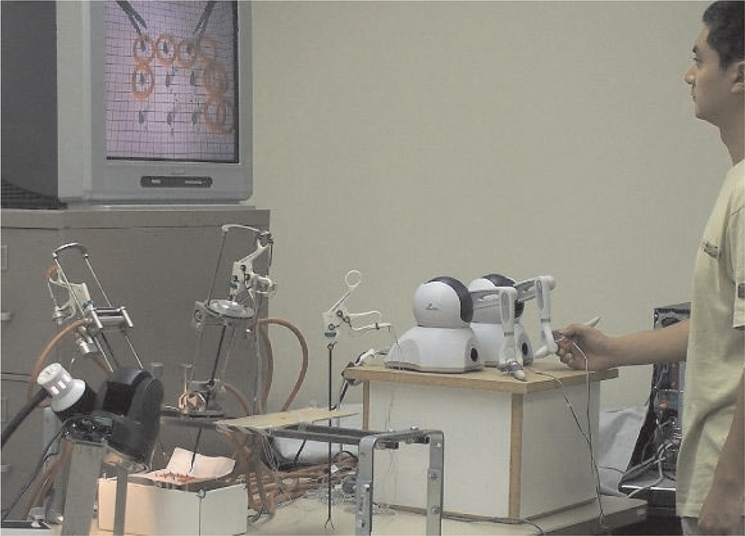
The experimental setup is shown in Figure 13.
Fig. 13.
Experimental setup for user testing.
7.2. Tasks
Two tasks were designed for both manual MIS instrument operation and robotic MIS teleoperation.
7.2.1. Task 1 (Pick and Place)
The gripper instrument is used to pick up nine rings and place them on pegs. The pegs are arranged in a grid with 20 mm separation and the rings were lined up against the edge of the tray containing the pegs before each task. For manual instrument operation, this task was performed once or twice for each participant and for robot instrument teleoperation, the task was performed four times with four different master–slave scaling ratios in order to find the best scaling factor.
7.2.2. Task 2 (Trajectory Following)
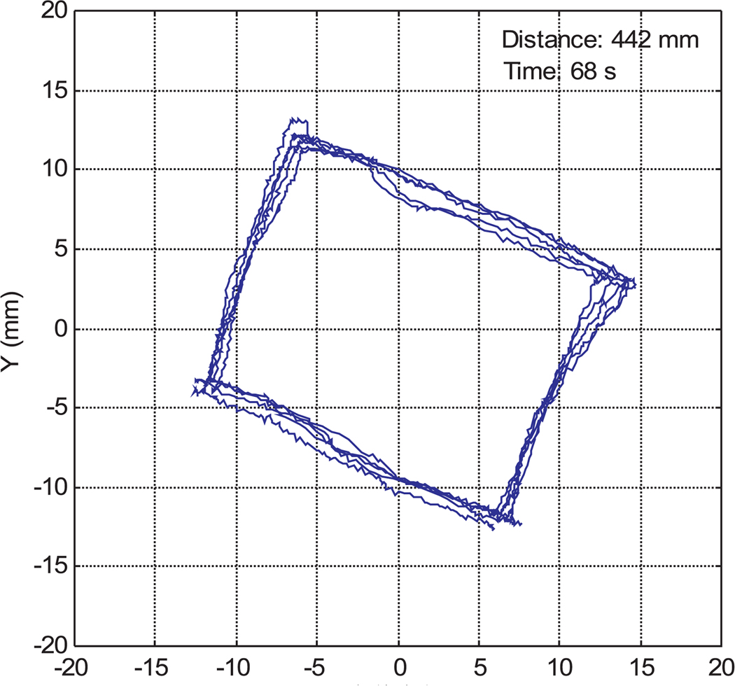
The gripper instrument is used to follow the given trajectory which is plotted on a horizontal plane. A 20 mm square was plotted on graph paper as the given trajectory. The participants were asked to control the tip of the surgical gripper instrument to move along the square trajectory. Each participant was asked to follow the trajectory in the clockwise direction for five circuits.
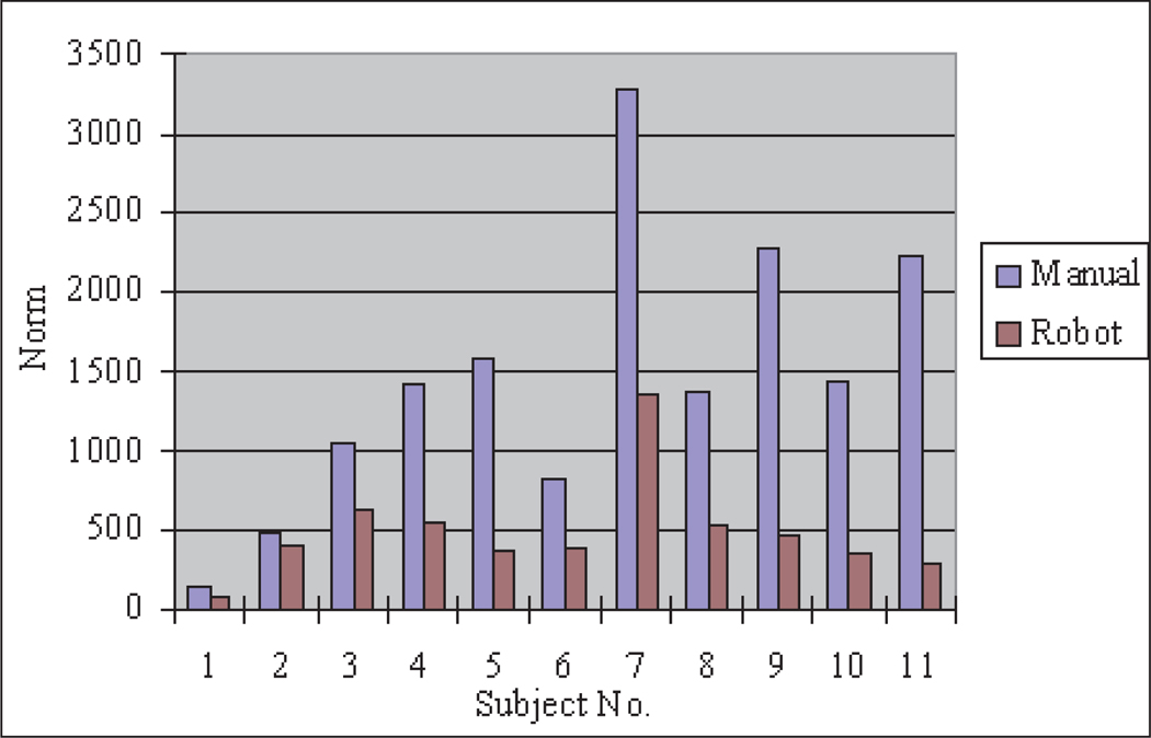
The task completion time and instrument tip motions were recorded by the optical motion tracker for each experiment. In order to avoid damaging the experimental models, the task samples were constructed from soft materials and mounted on a compliant mechanism. The positions of the instrument incision point, the task objects, the monitor and the user were arranged to be the same for both the manual and robot instrument operations. The task completion time, instrument tip moving distance and error norm were recorded for both the ring manipulation and the trajectory following tasks.
7.3. Task 1 Results
7.3.1. Task Completion Time
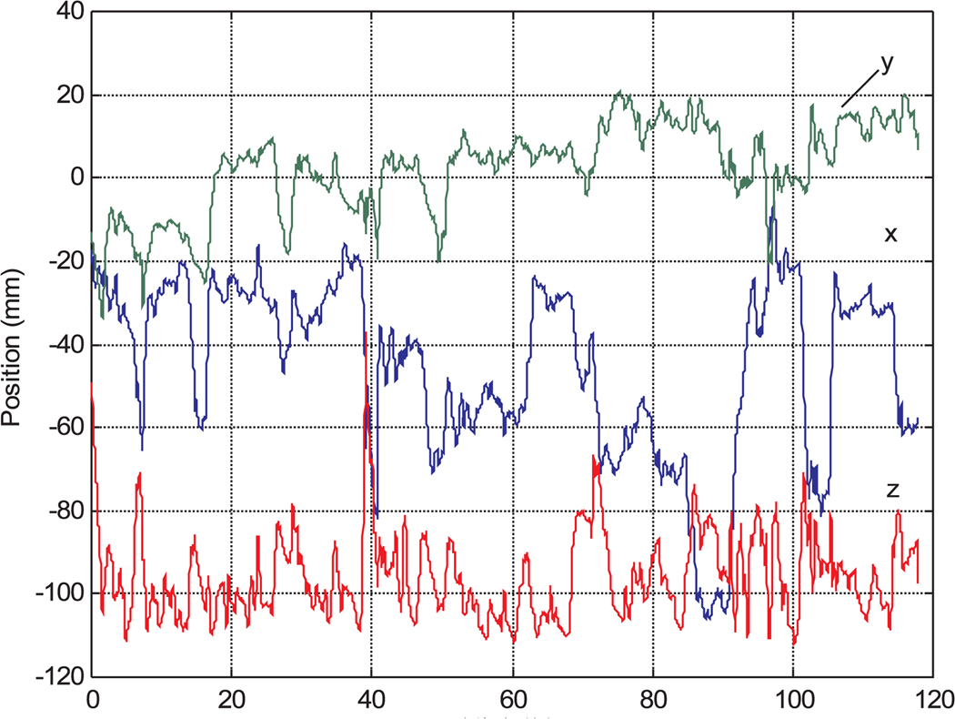
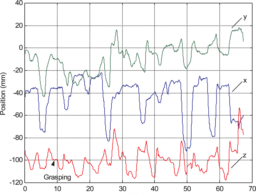
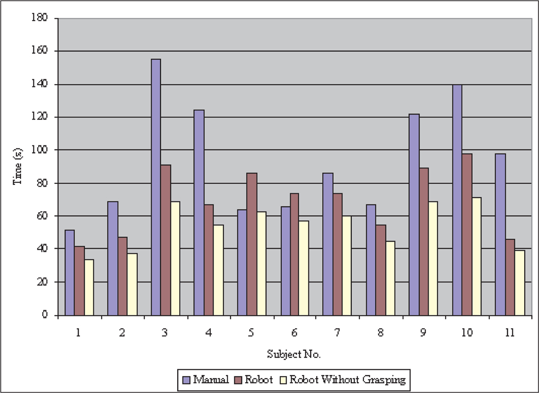
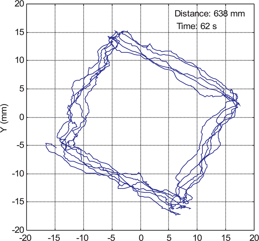
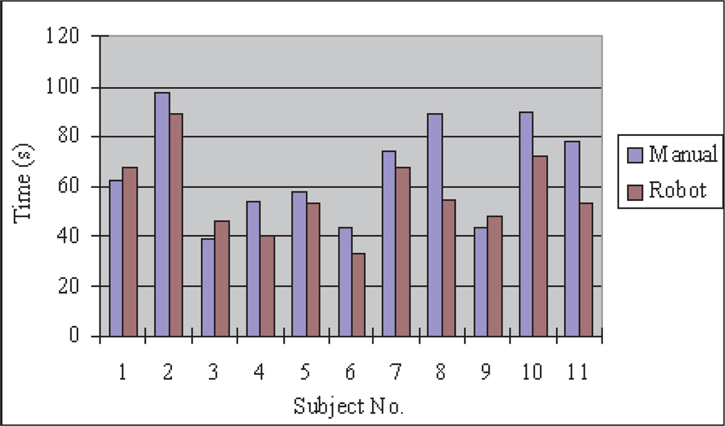
Figures 14 and 15 show the motion data of subject 4 from manual and robot operations. There are significant vibrations in manual operation caused by limited operation skill and hand tremors. The motion trajectory of the robotic teleoperation system is very smooth. There are pauses in the robot motion trajectories during grasping operations in Figure 15, however, because without any force feedback or depth perception in the robotic teleoperation, the participants had to be very careful to operate the wheel encoder in the teleoperation master to firmly grasp the ring. Figure 18 is the task completion time comparison between manual instrument operation and robotic teleoperation for each participant. The data of subject 1 is from the author. Although the other participants spent most of the practice time on manual instrument operation, the data show that manual instrument operation takes more time than robot teleoperation except for subjects 5 and 6.
Fig. 14.
Instrument tip motion data for manual operation.
Fig. 15.
Instrument tip motion data in robotic teleoperation.
Fig. 18.
Completion time for task 1.
It was apparent during testing that users spent more time grasping during robotic operation than in manual operation. In order to find the time spent on grasping during robot teleoperation, we estimated the grasping time from the nine motionless periods in the motion trajectory data sequences as can be seen in Figure 15. The average grasping time is about 21% of the total teleoperation time in the moving ring task, but is negligible in the manual task data as the users can grasp the rings while moving the instrument. This difference is most likely a result of the lack of force feedback in the gripper motion in teleoperation.
7.3.2. Instrument Tip Motion Distance
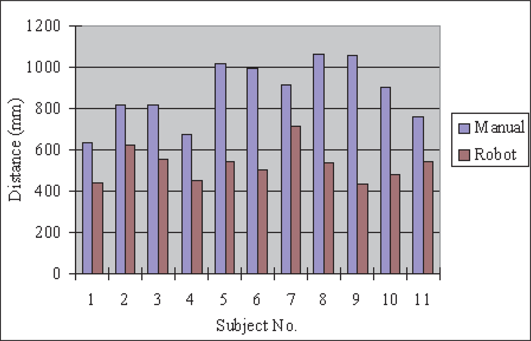
The total distance covered by the instrument tip can be used to represent the degree of vibration, which depends on skill and hand tremors. Increased instrument vibration can cause larger extra distance in the instrument tip displacements which may increase the possibility of tissue injuries in surgical procedures. The instrument tip moving distance is calculated by integrating the recorded trajectory from the data acquired by the motion tracking system. Figure 19 shows the instrument tip motion distance comparison between manual instrument and robot instrument operation for each participant. From the data in the figure, the instrument tip motion distance in manual operation varies greatly for different participants because of their different hand tremors and skills. In the robot instrument operation, the instrument tip motion distance is decreased for each participant.
Fig. 19.
Instrument tip distance for task 1.
7.3.3. Master–Slave Scaling Ratio in Robot Instrument Operation
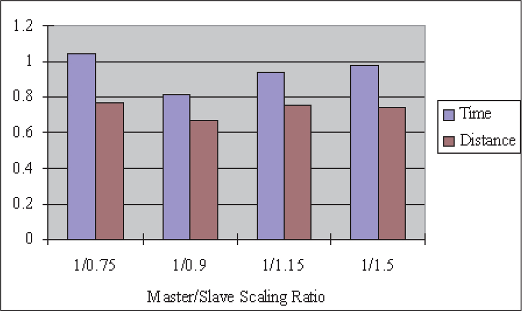
To understand the effects of the master–slave scaling ratio on task completion times, the following master–slave scaling ratios were used in the experiments: 1/0.75, 1/0.9, 1/1.15 and 1/1.5. Each participant was asked to perform the same moving ring task with different scaling ratios.
Figure 20 shows the result of different master–slave scaling ratio effects on the average normalized task times and distances, calculated by first normalizing each subject’s data by letting the value in teleoperation be divided by the value in manual operation, then calculating the average value from all of the participants at the corresponding scaling ratio. The average normalized task completion time for the robotic teleoperation system depends on the master–slave scaling ratio. For the ring placement experiment, the best scaling ratio is 1/0.9. Although theoretically a larger master–slave scaling ratio could achieve smoother and more accurate motion, the motion is slower, the task completion time is longer and the user may become fatigued. Also too large a master–slave scaling ratio for large-scale slave operation may cause the master device to reach the limit of its motion range, which may cause non-linear characteristics in the control system and a feeling of discontinuity for the user. Therefore, a larger master–slave scaling ratio is more suitable for smaller-scale operation to realize high precision. On the other hand, too small a master–slave scaling ratio will achieve more rapid motion in the slave, but will cause added undesired motions if the user’s hand moves too fast owing to the limited response bandwidth of the teleoperation system and the difficulty to precisely control the slave. Thus, too small a master–slave scaling ratio increases task completion times and motion distances. These conclusions can be verified from the data in Figure 20, where the best master–slave scaling ratio is 1/0.9, while with larger or smaller master–slave scaling ratios the time and distance are increased.
Fig. 20.
Scaling ratio effects.
7.4. Task 2 Results
Figures 16 and 17 are sample instrument tip trajectories for manual and teleoperated tasks with a 1/0.9 master–slave scaling ratio. The trajectory of the manual operation is much coarser owing to hand tremors and vibrations. In the teleoperation data, although there are some tremors from the teleoperation master device, the trajectory is much more accurate and smoother than manual instrument operation.
Fig. 16.
Instrument tip trajectory for manual operation.
Fig. 17.
Instrument tip trajectory in robotic teleoperation.
7.4.1. Task Completion Time
Figure 21 compares the task completion times for manual and teleoperated tasks for each participant. The times are similar for manual and robotic operations for most participants, as they tended to move the instrument tip at the same speed both manually and in teleoperation. Subjects 8, 10 and 11 showed a more significant improvement in their task completion times using the teleoperated robotic system.
Fig. 21.
Completion time for task 2.
7.4.2. Instrument Tip Moving Distance
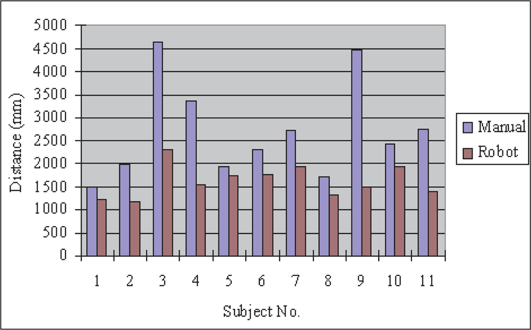
Figure 22 is the instrument tip moving distance comparison between manual and teleoperated instrument motion for each participant. The instrument tip moving distances in teleoperation are much smaller than in manual instrument operation because the robotic instrument teleoperation effectively filters out user hand tremors. Thus, the robotic teleoperation system can improve the operation accuracy and minimize the tissue injuries caused by unintentional hand tremors in typical manual operation.
Fig. 22.
Instrument tip distance for task 2.
7.4.3. Accuracy
Accuracy evaluation for the trajectory following task can be represented by the error norm between the measured trajectory and the desired trajectory. However, owing to the distortion of the two-dimensional visual projection, there is some discrepancy between the desired trajectory in the experimental sample and the desired trajectory on the TV monitor which displays a trapezoid instead of a square. Since the sides of the trapezoid are still a straight line, therefore we substitute the desired trajectory with an estimated trajectory which is approximated as lines by using a least-squares method from the measured data. The norm of the errors between the measured trajectory and the estimated desired trajectory are shown in Figure 23. The error norms are greatly decreased in the robot instrument operation, which means that more accuracy can be achieved by using the teleoperated robotic system than in typical manual MIS operation.
Fig. 23.
Error norm of task 2.
7.5. Discussion
The user tests as described were performed to evaluate the user interface performance of the system and results were given. The results show that the performance of the teleoperated robotic MIS system improves upon manual instrument operation with better ease of use, less task operation time, more accuracy, smoother motion and less vibration. We found in some results of the user tests that the robotic system generated more motion in the depth direction because the depth perception is lost by using two-dimensional video and there is no force feedback for the robotic master. This disadvantage can be compensated by surgical robotic system training, adopting three-dimensional video or providing force feedback to the master. The homemade mouse wheel type encoder to control the gripper instead of the buttons improves dexterity, but its location may impede the master’s motion in some master positions. Also the encoder resolution is limited.
The difficulties encountered during the user tests with fine control of gripping forces in teleoperation have led us to begin the development of grip force feedback for the user. A linear potentiometer is used to sense finger separation in a gripper mechanism on each teleoperation master, a miniature load cell is used to measure gripping forces in each robotic instrument, and a miniature voice coil actuator is used to generate feedback forces on the fingers of the user.
8. Conclusion
Our teleoperated surgical robot system is currently complete and provides functionality equivalent to commercial systems. Our small, lightweight system also provides advantages, however, in terms of its ease of set-up and use, access to the patient, safety and cost.
At less than 2 kg, each manipulator is portable and can be easily lifted with one hand and fixed to the operating table in the desired position above the abdomen of the patient. As all of the components of the system are autoclavable and immersible in cleaning fluids, the manipulators and robotic instruments can be sterilized and cleaned using the same standard procedures used for any other surgical equipment, and no sterile plastic draping is required for the surgical robot system. The reduced size and simple setup procedures of the robotic surgical system reduce the setup time and allow the system to be easily integrated into operating room suites. Furthermore, there are no time-consuming initialization procedures such as homing or setting motion limits to be completed before operating the surgical robot system.
Owing to the small size of the manipulators, which do not occupy any space on the floor or next to the operating table, the patient remains accessible from all sides by operating room personnel while the robotic surgical system is in place. The surgeon can remain in close proximity to the patient while operating the teleoperation master console. The motors and gear reductions which position the endoscope and instrument manipulators are easily backdrivable when the motor currents are switched off, so each manipulator can be directly positioned by hand if desired at any time. Quick-release clamps secure the endoscope and instruments to the manipulators and each manipulator to the support frame on the operating table, so that any component of the system can be removed and replaced easily and quickly at any time, for example to clean the endoscope lens or to switch between different cutting, grasping or cautery instruments. It is also quick and straightforward to switch between manual and teleoperated surgery modes by removing any or all of the manipulators, as there may be advantages to operating in one mode or the other at different times during the same procedure. For example, the immediacy and simplicity of manual operation may be preferred during initial, exploratory stages of a procedure, but the teleoperated system can be used at times when increased precision and dexterity is desired such as when suturing in difficult positions.
The small size and mass of the manipulators and the small motor torques required to drive them provide an intrinsic safety benefit compared with the larger, more massive arms typical of industrial manipulators. The likelihood of damage to internal tissues owing to unintended contact with teleoperated instruments is reduced.
We plan to begin evaluation of the complete system by enlisting surgeons associated with the University of Hawaii School of Medicine to perform surgical procedures on anatomical models using the teleoperated system, then proceed to preclinical trials on animal and cadaver models. It is especially encouraging that the endoscope manipulator in our system used separately has already received CE marking certification and is currently being used in trials in vivo, and our instrument manipulators are based on a similar design and components.
References
- Adhami L, Coste-Manière È. Positioning teleoperated surgical robots for collision-free optimal operation; Proceedings of the 2002 IEEE International Conference on Robotics and Automation (ICRA’02); 2002. [Google Scholar]
- Adhami L, Coste-Manière È. Optimal planning for minimally invasive surgical robots. IEEE Transactions on Robotics and Automation. 2003;19(5):854–863. [Google Scholar]
- Aiono S, Gilbert JM, Soin B, Finlay PA, Gordon A. Controlled trial of the introduction of a robotic camera assistant (EndoAssist) for laparoscopic cholecystectomy. Surgical Endoscopy. 2002;16(9):1267–1270. doi: 10.1007/s00464-001-9174-7. [DOI] [PubMed] [Google Scholar]
- Berkelman P, Cinquin P, Boidard E, Troccaz J, Letoublon C, Long J-A. Development and testing of a compact endoscope manipulator for minimally invasive surgery. Computer Aided Surgery. 2005;10(1):1–13. doi: 10.3109/10929080500252563. [DOI] [PubMed] [Google Scholar]
- Berkelman P, Troccaz J, Cinquin P. Body-supported medical robots: A survey. Journal of Robotics and Mechatronics. 2004;16(5):513–519. [Google Scholar]
- Berkelman PJ, Boidard E, Cinquin P, Troccaz J. LER: The light endoscope robot; IEEE/RSJ International Conference on Intelligent Robots and Systems; Las Vegas, NV: 2003a. pp. 2835–2840. [Google Scholar]
- Berkelman PJ, Whitcomb LL, Taylor RH, Jensen P. A miniature instrument tip force sensor for robot-assisted microsurgical manipulation with enhanced force feedback. IEEE Transactions on Robotics and Automation. 2003b;19(5):917–922. [Google Scholar]
- Buess GF, Arezzo A, Schurr MO, Ulmer F, Fisher H, Gumb L, Testa T, Nobman C. A new remote-controlled endoscope positioning system for endoscopic solo surgery—the FIPS endoarm. Surgical Endoscopy. 2000;14:395–399. doi: 10.1007/s004640020066. [DOI] [PubMed] [Google Scholar]
- Butner SE, Ghoudoussi M, Wang Y. Robotic surgery—the transatlantic case; International Conference on Robotics and Automation; Washington, DC: IEEE; 2002. pp. 1882–1888. [Google Scholar]
- Coa CGL, Rogers G. Robot-assisted minimally invasive surgery: the importance of human factors analysis and design. Surgical Technology International. 2004;12:73–86. [PubMed] [Google Scholar]
- Falk V, Diegeler A, Walther T, Banusch J, Brucerius J, Raumans J, Autschbach R, Mohr FW. Total endoscopic computer enhanced coronary artery bypass grafting. European Journal of Cardiothoracic Surgery. 2000;17(1):38–45. doi: 10.1016/s1010-7940(99)00356-5. [DOI] [PubMed] [Google Scholar]
- Finlay PA. Clinical experience with a goniometric head-controlled laparoscope manipulator; IARP Symposium on Medical Robotics; Vienna: 1996. [Google Scholar]
- Franzino RJ. The Laprotek surgical system and the next generation of robotics. Surgical Clinics of North America. 2003;83(6):1317–1320. doi: 10.1016/S0039-6109(03)00171-3. [DOI] [PubMed] [Google Scholar]
- Geis WP, Kim HC, Brennan EJ, Jr, McAfee PC, Wang Y. Medicine Meets Virtual Reality: Health Care in the Information Age. San Diego, CA: 1996. Robotic arm enhancement to accommodate improved efficiency and decreased resource utilization in complex minimally invasive surgical procedures; pp. 471–481. [PubMed] [Google Scholar]
- Guthart GS, Salisbury JK. The Intuitive (TM) telesurgery system: overview and application; International Conference on Robotics and Automation; San Francisco, CA: IEEE; 2000. pp. 618–621. [Google Scholar]
- Kappert U, Cichon R, Schneider J, Gulielmos V, Tugtekin SM, Matschke K, Schramm I, Schueler S. Closed-chest coronary artery surgery on the beating heart with the use of a robotic system. Journal of Thoracic and Cardiovascular Surgery. 2000;120(4):809–811. doi: 10.1067/mtc.2000.109543. [DOI] [PubMed] [Google Scholar]
- Kavoussi LR, Moore RG, Adams JB, Partin AW. Comparison of robotic versus human laparoscopic camera control. Journal of Urology. 1995;154:2134–2136. [PubMed] [Google Scholar]
- Kitagawa M, Okamura AM, Bethea B, Gott V, Baumgartner W. Medical Image Computing and Computer Asssisted Intervention (Lecture Notes in Computer Science. Vol. 2488. Berlin: Springer; 2002. Analysis of suture manipulation forces for teleoperation with force feedback; pp. 155–162. [Google Scholar]
- Kobayashi E, Masamune K, Sakuma I, Dohi T, Hashimoto D. A new safe laparoscopic manipulator system with a five-bar linkage mechanism and optical zoom. Computer Aided Surgery. 1999;4(4):182–192. doi: 10.1002/(SICI)1097-0150(1999)4:4<182::AID-IGS2>3.0.CO;2-U. [DOI] [PubMed] [Google Scholar]
- Long J-A, Cinquin P, Troccaz J, Voros S, Berkelman P, Descotes J-L, Letoublon C, Rambeaud J-J. Development of miniaturized light endoscope-holder robot for laparoscopic surgery. Journal of Endourology. 2007;21(8):911–914. doi: 10.1089/end.2006.0328. [DOI] [PubMed] [Google Scholar]
- Loulmet D, Carpentier A, d’Attellis N, Mill F, Rosa D, Guthart G, Berrebi A, Cardon C, Ponzio O, Aupecle B. First endoscopic coronary artery bypass grafting using computer assisted instruments. Journal of Thoracic and Cardiovascular Surgery. 1999;118(1):4–10. doi: 10.1016/S0022-5223(99)70133-9. [DOI] [PubMed] [Google Scholar]
- Lum M, Trimble D, Rosen J, II KF, King H, Sankaranarayanan G, Dosher J, Leuschke R, Martin-Anderson B, Sinanan MN, Hannaford B. Multidisciplinary approach for developing a new minimally invasive surgical robotic system; IEEE-RAS/EMBS International Conference on Biomedical Robotics and Biomechatronics; Pisa: 2006. [Google Scholar]
- Ma J, Berkelman P. Control software design of a compact laparoscopic surgical robot system; IEEE/RSJ International Conference on Intelligent Robots and Systems; Beijing: 2006. pp. 2345–2350. [Google Scholar]
- Ma J, Berkelman P. Task evaluations of a compact laparoscopic surgical robot system; IEEE/RSJ International Conference on Intelligent Robots and Systems; San Diego, CA: 2007. pp. 398–403. [Google Scholar]
- Madhani AJ. PhD Thesis. Massachusetts Institute of Technology; 1998. Design of teleoperated surgical instruments for minimally invasive surgery. [Google Scholar]
- Makino H, Furuya N. SCARA robot and its family; International Conference on Assembly Automation; 1982. pp. 433–444. [Google Scholar]
- Marescaux J, Leroy J, Gagner M, Rubino F, Mutter D, Vix M, Butner S, Smith MK. Transatlantic robot-assisted telesurgery. Nature. 2001;413:379–380. doi: 10.1038/35096636. [DOI] [PubMed] [Google Scholar]
- Massie TH, Salisbury JK. Dynamic Systems and Control. Chicago, IL: ASME; 1994. The Phantom haptic interface: a device for probing virtual objects; pp. 295–299. [Google Scholar]
- Mettler L, Ibrahim M, Jonat W. One year of experience working with the aid of a robotic assistant (the voice-controlled optic holder AESOP) in gynaecological endoscopic surgery. Human Reproduction. 1998;13:2748–2750. doi: 10.1093/humrep/13.10.2748. [DOI] [PubMed] [Google Scholar]
- Munoz VF, Vara-Thornbeck C, DeGabriel JG, Lozano JF, Sanchez-Badajoz E, Garcia-Cerezo A, Toscano R, Jimenez-Garrido A. A medical robotic assistant for minimally invasive surgery; International Conference on Robotics and Automation; San Francisco, CA: IEEE; 2000. pp. 2901–2906. [Google Scholar]
- Polet R, Donnez J. Gynecologic laparoscopic surgery with a palm-controlled laparoscope holder. Journal of the Americal Association of Gynecologic Laparoscopists. 2004;11(1):73–78. doi: 10.1016/s1074-3804(05)60015-1. [DOI] [PubMed] [Google Scholar]
- Pott P, Kopfle A, Wagner A, Badreddin E, Manner R, Weiser P, Scharf H-P, Schwarz M. State of the art of surgical robotics; Perspective in Image-Guided Surgery: Proceedings of the Scientific Workshop on Medical Robotics, Navigation and Visualization; Germany: Remagen; 2004. pp. 375–382. [Google Scholar]
- Reichenspurner H, Demaino R, Mack M, Boehm D, Gulbins H, Detter C, Meiser B, Ellgas R, Reichart B. Use of the voice controlled and computer-assisted surgical system Zeus for endoscopic coronary artery surgery bypass grafting. Journal of Thoracic and Cardiovascular Surgery. 1999;118:11–16. doi: 10.1016/S0022-5223(99)70134-0. [DOI] [PubMed] [Google Scholar]
- Sackier JM, Wang Y. Robotically assisted laparoscopic surgery: from concept to development. In: Taylor RH, Lavallee S, Burdea GC, Mosges R, editors. Computer Integrated Surgery: Technology and Clinical Applications. Cambridge, MA: MIT Press; 1995. pp. 577–580. [Google Scholar]
- Tavakoli M, Patel R, Moallem M. A force reflective master–slave system for minimally invasive surgery; IEEE/RSJ International Conference on Intelligent Robots and Systems; Las Vegas, NV: 2003. pp. 3077–3082. [Google Scholar]
- Taylor RH, Funda J, Eldridge B, Gomory S, Gruben K, LaRose D, Talamini M, Kavoussi L, Anderson JA. Telerobotic assistant for laparoscopic surgery. In: Taylor RH, Lavallee S, Burdea GC, Mosges R, editors. Computer Integrated Surgery: Technology and Clinical Applications. Cambridge, MA: MIT Press; 1995. pp. 581–592. [Google Scholar]
- Taylor RH, Stoianovici D. Medical robotics in computer-integrated surgery. IEEE Transactions on Robotics and Automation. 2003;19:765–781. [Google Scholar]
- Van Meer F, Giraud A, Esteve D, Dollat X. A disposable plastic compact wrist for smart minimally invasive surgical tools; IEEE/RSJ International Conference on Intelligent Robots and Systems; Alberta: 2005. pp. 919–924. [Google Scholar]
- Voros S, Orvain E, Cinquin P, Long J-A. Automatic detection of instruments in laparoscopic images: a first step towards high level command of robotized endoscopic holders; IEEE-RAS/EMBS International Conference on Biomedical Robotics and Biomechatronics; Pisa: 2006. [Google Scholar]


