

Abstract
Background
Droplets exhaled during normal breathing and not associated with coughing may pose hazardous agents to infective diseases dissemination. The objective is to explore the physical mechanism, which may lead to droplets formation.
Methods
We hypothesize that liquid menisci occlusions, which may form inside small airways, travel along the airway, may lose mass and finally disintegrate into small droplets. This hypothesis was numerically investigated applying physiologically plausible values of the phenomenological coefficients and geometrical conformations.
Results
We show that three important dimensionless parameters control the motion and disintegration of menisci: the dimensionless mucus layer thickness, the dimensionless menisci initial thickness (all scaled by the airway radius), and the capillary number. Menisci traveling within airways may either remain at equilibrium or diminish or increase in size. Menisci that diminish in size may collapse into the mucus layer; form a large droplet that contains most of the menisci mass before disintegration; or form a larger number of small droplets (we show the forming of three or four droplets in a single occluded airway).
Conclusions
A critical capillary number for menisci at equilibrium could be defined. It was shown that menisci tend to diminish in size as the capillary number increases above the critical value, and a number of small droplets may be formed during normal breathing.
Key words: airway occlusion, liquid aerosols, meniscus breakup
Introduction
The process of respiration is frequently accompanied with the formation of liquid, micron-size aerosols exhaled from the pulmonary airways.(1–4) These aerosols may spread infecting diseases, carrying, for instance, influenza viruses, or anthrax germs. Large aerosol drops precipitate relatively fast to the ground while small droplets may stay in the atmosphere for a long period of time, be carried by air to large distances, and eventually be inhaled by other humans. Therefore, investigating the formation of aerosol microparticles in the respiratory system that is not associated with coughing may provide an additional key for management of viral infections dissemination.
Theoretically, aerosol droplets may be formed in small airways, lined with liquid, following two mechanisms: (1) condensation of saturated vapor due to changes in thermodynamic balance between gas and liquid phases; (2) disintegration of a liquid body (film, meniscus, jet) to small fragments due to hydrodynamic instability.
A thermodynamic formation mechanism of aerosol drops appears to be improbable due to the absence of significant pressure and thermal gradients in the respiratory system, which could lead to phase aggregative transitions between gas and liquid. Also, a thermodynamic approach is unable to explain the effect of the rheological properties of the liquid on the size of formed aerosol microparticles. Existence of such dependence is shown in an experimental assay carried out by Edwards,(5) according to which viscosity and surface tension influence droplet size. Therefore, we conjecture that the formation of bioaerosols is a consequence of hydrodynamic instability of the liquid lining the airways.
A common flow model of pulmonary airways supposes that air flows inside a duct lined with a viscous liquid layer (airway surface liquid, ASL), a variant known as core–annular flow (CAF). Theoretically, in this case, hydrodynamic instability may develop following either a Kelvin-Helmholtz or a Rayleigh-Taylor (capillary) instability pattern.
The mechanism that governs the Kelvin-Helmholtz instability for core–annular flow has extensively been studied theoretically and experimentally. Kataoka,(6) in his experimental study, suggested a correlation that makes it possible to determine the size of drops “captured” by air flow from break points of waves formed on the liquid surface due to the Kelvin-Helmholtz instability. This phenomenon is observed, if both liquid and gas have relatively high Reynolds numbers: ReL ≥ 102, Reg ≥ 104, respectively. Evrensel(7) theoretically studied CAF stability, assuming that the CAF is a fully developed Poiseuille flow. Solving Orr-Sommerfeld equations he studied the effect of critical thickness ratios within the range 0.1 < hc/R < 0.6, where hC is the thickness of the liquid layer lining the tube walls and R is the tube radius. Critical Reynolds numbers for such cases were within the range 3000 < ReC < 10,000. He also showed that the critical Reynolds numbers decreased with increasing hc/R. Similar results were obtained by Clarke.(8) Analyzing these data, we may conclude that Kelvin-Helmholtz instability is conditioned by high values of Reynolds numbers and is irrelevant, in connection with the airflow in the small airways inside the lung for which the Reynolds number is of order unity or less and characterized by quasi-steady creeping flow.
Thus, a tube occlusion by a liquid meniscus is a result of the Rayleigh instability or the elastocapillary instability (in the case of elastic tubes). This phenomenon is described in detail by refs.(9–23), and many other investigators. Flows inside deformable channels were addressed by refs.(24–27) and others in many earlier studies.
In this article we assume that a meniscus is formed inside an inflexible airway. A schematic of meniscus initial configuration is shown in Fig. 1. Capillary instability leads initially to formation of an unduloid (Fig. 1b,(28)). Further development of the unduloid depends on the ratio hc/R. Its critical value for a rigid tube is hcr ≈ 0.14R.(12) If hc/R exceeds that critical value, a meniscus is formed (Fig. 1c). For a smaller ratio the unduloid maintains a steady shape Figure 1b. It is also shown that, by increasing tube flexibility, the critical thickness value hc/R is decreased. Accounting for the viscoelastic properties of the mucos (not addressed in this article) may also change hcr. For healthy pulmonary airways h ≈ 0.2R, that is, the probability of menisci formation is high in the human respiratory system, especially at low lung volume during expiration.
FIG. 1.

Stages of meniscus formation in lung airways (Rayleigh instability). (a) Liquid-lined tube. (b) Development of an unduloid. (c) Meniscus occlusion. (d) Meniscus clearance. [From ref. (23).]
The fate of menisci formed in the small airways attracted only limited attention in the past. We hypothesize that such liquid menisci travel in the pulmonary airways, deform under various phenomenological and kinematical conditions and may finally disintegrate and form small aerosol droplets. Somewhat close problems were studied by Bretherton(29) and Howell,(30) Grotberg and Waters,(31) who concentrated on the steady motion of interfaces between liquid and gas. Bretherton(29) addressed a semi-infinite gas bubble using the Landau-Levich approach to obtain an approximate analytic solution for the bubble motion along a capillary tube filled with viscous liquid. Howell(30) investigated the motion of a liquid meniscus in liquid-lined flexible tube and analyzed the case of a stabilized meniscus motion assuming that the flow inside the meniscus is governed by the steady Stokes equations while Grotberg and Waters(31) added the effect of surfactants.
In this paper we focus on the conditions required for menisci consisting of two gas–liquid interfaces to move unsteadily and disintegrate forming droplets.
Methods
Model description
The model of occluded pulmonary airways by liquid menisci is schematically depicted in Figure 2a. The following definitions are used henceforth: μa, μm are the dynamic viscosities of air and liquid (ASL), respectively; ρa, ρm are the densities of air and ASL, respectively; U is the mean air velocity; R is the airway radius; h0 stands for the initial thickness of the liquid layer lining the airway walls (ASL); b0 is the initial meniscus thickness; b is the meniscus thickness at its center at arbitrary time t; σ is the surface tension coefficient at the mucus–air interface.
FIG. 2.

(a) Schematic presentation of a closed pulmonary airway. (b) Schematic illustration of the boundary edges and faces of an axisymmetric slice of the solution domain.
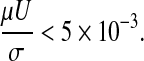
Our model includes the following assumptions that allow simplifying the problem and making the problem computationally more tractable. (1) ASL is homogeneous and Newtonian. [It is well known that ASL is represented by binary layer consisting of two liquids, namely, mucus layer and periciliary (or serous) liquid layer, each of those liquids is non-Newtonian and possesses thixotropic and elastic properties.(32) Alas, the rheological constitutive equation for ASL has not yet been fully explored. Thus, this assumption can be alleviated when a better rhelogical model is formulated.] (2) The ASL initial thickness is uniform throughout the capillary length: h(t = 0) = h0 = const. (3) Surfactants are evenly distributed throughout the interface, including the meniscus surface and, consequently, Marangoni flow effects are not considered. (To alleviate this assumption one needs to introduce a conservation equation for surfactant concentration at the liquid–air interface and an equation relating surface tension to surfactant concentration. See, for example, Haber and Zelig(33) for a detailed analysis of Marangoni effects inside alveoli. This effect on meniscus propagation and breakup awaits future exploration.) (4) Initially, the liquid meniscus possesses a cylindrical shape. (It is shown afterward that this assumption is a matter of convenience and does not bear any influence on the final results.) (5) The capillary is rigid and does not deform during the entire computation process. (It is shown later that the time required for a meniscus to move before it disintegrates is much smaller than the breathing period, the time scale governing airway deformation prior breakup. During breakup strong pressure gradients may occur that may cause airway deformation. This phenomenon is not dealt with in this paper.) (6) As Bond number
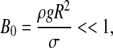 |
it is possible to neglect gravity effects and assume that the flow inside the tube is axisymmetric. (The Bond number is a dimensionless number expressing the ratio of body forces—in this case gravitational—to surface tension.) (7) The flow is slow and air can be considered incompressible.
Dimensional analysis
A straightforward dimensional analysis yields that the meniscus thickness b depends upon time and six dimensionless parameters, namely,
 |
(1) |
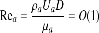
where Rea is the Reynolds number for air flow inside the lung airway and Ca is the capillary number
 |
(The capillary number is a dimensionless number expressing the ratio of hydrodynamic shear forces to surface tension at a gas–liquid interface.) Notice that pressure gradient ΔP is not an independent parameter, as it is related to the air mean velocity U.
As the phenomenological properties of ASL of healthy humans are relatively invariable we disregard changes in the density and viscosity ratios μa/μm, ρa/ρm and focus on the impact of the other parameters on meniscus thickness,
 |
(2) |
Governing equations
We consider our flow model as a two-phase (air–mucus) fluid in a VOF (volume of fluid method) formulation. For two-phase incompressible fluid, VOF appears as a system of Equations (3)–(8): the incompressible Navier-Stokes equation,
 |
(3) |
the continuity equation,
 |
(4) |
and the volume fraction equation,
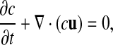 |
(5) |
where c is the volume fraction with a value of unity in mucus and zero in air. The local density and viscosity are defined as:
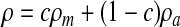 |
(6) |
 |
(7) |
The continuum surface force (CSF) has been employed to calculate the surface tension force:
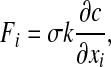 |
(8) |
where k is the curvature of the mucus-air interface.
Boundary and initial conditions
The boundary and initial conditions governing the foregoing system of Equations (3)–(8) are (see Fig. 2b),
Edge AB: No slip condition. ux = ur = 0 at r = ±R.
Edge BC & CD: Fully developed flow.
 . c = 0 at edge CD and c = 1 at edge BC.
Edge DE: Axis symmetry.
Edge EF: Uniform flow of Air: ux = U, ur = 0, c = 0.
Edge FA: Uniform flow of Mucus (ASL): ux = Um; ur = 0, c=1.
The Initial Conditions are as follows,
At t = 0:
u = 0 For Air and Mucus Flows;
c = 0 at domains F-G-I-E and H-C-D-J, which contain the air phase;
c = 1 at domain F-C-H-J-I-G-F, which contains the mucus (ASL) phase.
Application of steady-flow conditions at the airway upstream and downstream location appears to be more suitable than specification of a pressure gradient. In other words, the foregoing set of conditions tacitly supposes that the respiratory system maintains a required air flow. However, as shall be shown later, meniscus travel time until disintegration is much smaller than the breathing period. Thus, no large variations in either velocity or pressure gradients is expected before meniscus breakup. The distance between airway upstream cross-section and the meniscus was chosen so that uniform flow entering the airway could develop.
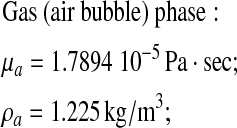
The physical and physiological set of applied parameters
The numerical computation was applied to airway radii and air velocity values, which correspond to 12th–13th generation bronchioles at FRC (based on the dichotomy of human pulmonary airway model suggested by Weibel(34) with TLC volume of 6400 mL and FRC volume of 2500 mL).
Thus, the following values for the phenomenological parameters were assumed,
 |
The latter value of mucus viscosity is based on a posteriori calculations of reasonable pressure gradients, which are known to exist in the lung. Assuming a characteristic meniscus width (b0 ∼ R), the pressure gradient for the chosen viscosity and thickness of mucus lining h ≈ 0.2R, corresponds to an average pleural pressure of an adult, namely, ΔP ≈ O(1) cmH2O. Actually, as a non-Newtonian fluid the mucus viscosity varies within a wide range: μm ∼ 10−3−101 Pa · s(35,36). At normal breathing conditions the total air flow rate is 0.5 liters/sec. Consequently, at the 14th generation bronchioles the mean air velocity is about Ua ≈ 0.02 m/sec and
 |
Thus, the flow is almost creeping, and we expect that physiologically plausible variations in the Reynolds number would play a smaller role than that of the other parameters. Namely, for fixed values of fluid properties the time evolution of the meniscus thickness for a range of capillary numbers, initial values of the meniscus width and mucus lining thicknesses will be examined.
 |
(9) |
However, note that the numerical solution incorporates the effects of the nonzero Reynolds number.
The value of h0/R may vary with age or due to illness(37) and its effect was investigated within the physiological range h0/R ∼ 0.1–0.3. The range of initial meniscus thickness b0/R (or volume) is much more difficult to estimate, and little is known from past observations. Its effect was considered within a wide range b0/R ∼ 0.5–3.0. The capillary number Ca depends on the air-mucus surface tension. For healthy humans σ ≈ 0.05 N/m, it varies with age and may be affected by respiratory diseases.(38) Its influence was investigated within the interval of σ ∼ (0.01–0.1) N/m (or, in this case, for capillary numbers within the range Ca ∼ 0.1–1.0).
The numerical scheme and its validation
A numerical solution of the system was obtained by using a commercial CFD software package FLUENT®, which includes a FVM (finite volume method) scheme, and its preprocessor GAMBIT®, used for our model grid construction. Standard quad elements placed in map-type distribution scheme were found to be most suitable for our axis–symmetric configuration. The computational domain contained 40,500 uniform cells with aspect ratio 1:2 and spacing of 4/3 μm in the direction of flow. A double precision coupled solver was chosen due to unsteady and multiphase nature of the problem. (See also Fig. 3, which illustrates the decreasing error vis-à vis the increasing number of elements.)
FIG. 3.

(a) Bubble velocity versus capillary number of Bretherton's problem. Star symbols depict VOF numerical results. Continuous line refers to Bretherton's analytical solution. All other symbols refer to experimental results (—Marchessault & Mason,(41)—Fairbrother @ Stubbs, × aniline, ○ benzene (horizontal tube), □ benzene (with evaporation precautions), • benzene (vertical tube). (b) The error in maximum air velocity at the airway upstream region vis-à-vis the number of volume elements used to calculate the velocity distribution.
To find air–mucus interface, algorithm GRS (Geometric Reconstruction Scheme approach) was applied. The program was run on a PC (Pentium® 4CPU 3.00 GHz 1 gb of RAM) and each run that followed the meniscus motion took about 72 h to complete.
Three benchmark problems that contain moving interfaces were employed to examine suitability of the VOF (“volume of fluid”) method of solution:
(A) The Bretherton's flow system, which includes a semiinfinite gas bubble moving in a liquid column. It was chosen as a benchmark problem because for the air–benzene combination its parameter set is similar to that employed in our problem with Re ∼ 100, Ca ∼ 10−2, Bo ∼ 10−3, and it is relatively well studied, both theoretically (Bretherton,(29) Ratulowski and Chang(39)), numerically using a FEM method (Heil(40)), and experimentally (Marchessault and Mason(41)).
A comparison was carried out for the following gas and liquid properties:
 |
Liquid (benzene) phase:
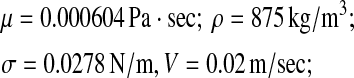 |
The theoretical solution for the air bubble speed is U=V (1 + W) where
 |
and V denotes the average speed of the benzene in the tube. In our case
 |
U = 0.02031 m/sec; and W = 0.01555; (see Fig. 3a).
According to Bretherton, this result is in error of no more than 10% provided
 |
Based on the present numerical solution by the VOF method U = 0.0204545 m/s and  .
.
Consequently, the numerical solution deviates from Bretherton's solution by less than 1%. Comparison of our numerical results with experimental data yielded a smaller than 5% error.
(B) Flow of air in a circular tube lined with Newtonian liquid. This problem should mimic closely Poiseuille flow. Such a field exists near the entrance in our problem and a comparison was made between solutions obtained for different number of elements. Figure 3b shows the decreasing error in air velocity at the airway axis with increasing number of elements.
(C) The velocity of a meniscus at steady state. A comparison was carried out with the solution obtained by Howell(30) and is shown in Figure 7b. The agreement with their results is excellent.
FIG. 7.

Critical capillary number (Cacr)dependence on; (a) meniscus initial thickness b1/R, (b) mucus layer thickness h0/R.
These tests validate that the VOF method yield accurate results for moving interfaces in a parameter space utilized in our problem.
Results and Discussion
Meniscus evolution
The assumed crude initial cylindrical shape of the meniscus (Fig. 2a) evolves through two different stages; it rapidly deforms into a physically plausible shape, governed mainly by surface tension forces, then it proceeds to move and change its shape in a slower pace. During the first stage the meniscus thickness (at its center) decreases to a value we shall term, henceforth, b1 and its two upstream and downstream faces become concave. (In further calculations, we shall refer to b1/R (meniscus thickness after reforming to physical shape) that occurs within t1 = 0.03 sec at most. This time interval was chosen empirically for our set of parameters and is the time interval required for a meniscus to transform from a cylindrical to its physical shape.) During the second slower stage, the meniscus moves downstream, its thickness increasing, decreasing, or remaining unaltered, an outcome strictly depending upon the chosen three parameter set. For two dimensionless parameters governing meniscus motion, the dimensionless lining thickness, h0/R, and the capillary number, Ca, we assumed plausible physiological values as explained in the Methods section where the latter may possess a broad spectrum of values due to the liquid non-Newtonian characteristics. The third important parameter b0/R is not known, to the best of our knowledge, from previous experimental data. We have chosen a value of the order 1, which seems plausible and was also assumed in Howell.(30) It also allows a comparison to be made between our numerical results and those obtained by Howell.(30)
A detailed study of the pressure and velocity field within the meniscus may provide a clue why the various scenarios of meniscus motion occur. Figure 4a and b illustrates the stream function contour lines and the corresponding pressure distribution for meniscus motion at equilibrium. Notice, that in Figure 4a a streamline extends beyond the liquid phase domain because it pertains to liquid and air phases alike. It shows that air and liquid velocity at the interface are continuous but their gradients are not. This reflects the fact that velocities and shear stresses are assumed continuous across the interface but viscosities of liquid and air differ. It also illustrates that the velocity vector near the front of the meniscus is not parallel to the interface, and thus the liquid phase is not contained within the existing location of the meniscus. Consequently, liquid is moved into the gas phase domain as the meniscus as a whole is traveling forward. Arrows in Figure 4b show typical direction of liquid motion within the meniscus, in accordance with the stream function depicted in Figure 4a. Points R, F, and C correspond to rear, front, and central parts of the meniscus, respectively.
FIG. 4.

meniscus at equilibrium (a) stream function contour lines. (b) pressure field.
The pressure gradients between the rear end and the meniscus center, ΔPRC, and that between the center and the front surface, ΔPCF reveal the following. In case the meniscus is at equilibrium, the foregoing pressure gradients are equal, and as a result, liquid inflow from the rear part to the center of the meniscus is balanced by liquid outflow from the center to the front part. This flow causes the visible forward meniscus motion without changing its volume. In the case of meniscus expansion, ΔPRC > ΔPCF, and inflow from the upstream part of the liquid lining toward the meniscus is larger than the volume of liquid outflow from the center of the meniscus toward the downstream part of the liquid lining. Similarly, in case of volume diminution, the reversed situation is observed.
Capillary number effects
The capillary number Ca for fixed values of b0/R and h0/R plays a significant role in determining the particular mechanism of meniscus motion, as surface tension σ is an important component establishing the pressure distribution within the meniscus according to the Young-Laplace's equation. Figure 5 portrays the time evolution of meniscus thickness (measured along the axis of symmetry) for various values of capillary numbers given that thickness b1 = 1.4R. It shows that: the rate of change in meniscus thickness is almost a constant; for small Ca numbers the meniscus undergoes a thickening process; for increasing Ca numbers, the rate of meniscus thickening decreases, reaching equilibrium (a zero thickening rate) at the critical value Cacr = 0.182; further increase of the Ca numbers results in increasing rates of meniscus thinning. Figure 6a–c depicts the three evolution scenarios of the meniscus shape at various times, when the initial value of the meniscus and mucus lining thicknesses for all these cases are b0/R = 2 and h0/R = 0.2. Notice that after the quick initial thickness diminution, the value of b1/R for all cases is reduced to about 1.4, a reference value that scales better the evolution of the meniscus thickness with time.
FIG. 5.

Meniscus thickness vs. flow time for various capillary numbers (Ca). An equilibrium state can be observed at Ca = 0.182 defined as the “critical capillary number: for which the meniscus preserves its shape. Lower capillary numbers result in meniscus thickening while higher values lead to meniscus thinning and eventually disintegration.
FIG. 6.


Motion of a meniscus along the airway. (a) The meniscus volume increases with time for below critical capillary number. (b) The meniscus volume remains unchanged (the equilibrium case) at critical capillary number. (c) The meniscus volume decreases with time for above critical capillary number.
Meniscus motion with its volume increasing with time. In Figure 6a a subcritical value of the capillary number is assumed. The figure illustrates that although the meniscus thickness increases, the thickness of the liquid layer lining the airway walls behind the meniscus decreases. Indeed, while moving, the meniscus “collects” liquid from the airway walls and gains mass. At time t = 0.09 sec its thickness has increased by almost 34% (from base value of b1/R = 1.4).
Steady meniscus motion (meniscus at equilibrium). In Figure 6b a critical capillary number is assumed. It illustrates the second scenario in which the meniscus is at equilibrium state, a case also analyzed by Howell.(30) The meniscus, after the short time of reforming from a cylindrical to a double concave shape, proceeds to move at a uniform velocity with its shape unaltered. The critical capillary number Cacr associated with the equilibrium state varies with the values of the other independent dimensionless parameters pertaining to the initial meniscus volume and the thickness of the fluid lining the airway.
Meniscus motion with its volume decreasing with time. In Figure 6c the case of a high capillary number above the critical is assumed. It depicts that as the meniscus thickness decreases during its motion the thickness of the liquid layer lining the capillary walls behind the meniscus increases. Indeed, while moving, the meniscus “donates” liquid to the capillary walls and the meniscus loses mass. For instance, at time t = 0.09 sec its thickness would decrease by 50% (from base value of b1/R = 1.4). As this process proceeds it would finally result in reduction of meniscus volume to a minimal critical value, it would lose stability and disintegrate. Within our proposed model of aerosol drops formation this scenario is the most relevant.
The critical capillary number
The importance of the critical capillary number was manifested in the previous section, and it is of value to investigate its dependence upon the two other remaining parameters, the dimensionless thicknesses of the meniscus b0/R and mucus lining h0/R shown in Figure 7a and b, respectively.
Figure 7a manifests that the critical capillary number (Cacr) dependence upon initial meniscus thickness b0/R can be divided into two distinct regions: it is a relatively a weak function of b0/R within a wide range of large b0/R-values (0.5 ≤ b0/R ≤ 3); it becomes strongly dependent upon b0/R within a range of small values of initial meniscus thicknesses (b0/R < 0.5). For large values of b0/R this is probably due to the fact that the upstream and downstream shape of the concave surfaces hardly vary with meniscus thickness, and thus the pressure fields inside the meniscus preserve the relation ΔPRC = ΔPCF (see Fig. 4b). For small values of b0/R this is no longer correct and instabilities will occur faster as the meniscus thickness becomes smaller.
Figure 7b illustrates the dependence of the critical capillary number (Cacr) upon the thickness of the mucus layer h0/R. An analytical solution for Cacr dependence upon h0/R was obtained by Howell.(30) For a rigid tube with homogeneous liquid lining h0/R = const. and b0 ∼ R1, the correlation appears as:
 |
(14) |
It should be noted that the computed Cacr values (Fig. 7b) are highly compatible with the analytical solution,(14) thus giving additional evidence of validity of our numerical model.
Also note that if the diameter of the airway decreases (toward the end of the exhaling period) the likelihood of meniscus forming in the airway increases. Because the critical capillary number is proportional to (h0/R),3/2 reduction in R is associated with a higher critical capillary number. Thus, if disintegration of occlusions are desired a smaller surface tension is required so that the capillary number is above the critical value.
Meniscus disintegration and droplet formation
A meniscus that undergoes thickness reduction, associated with capillary numbers above the critical, may reach a critical film thickness, become hydrodynamically unstable, and eventually collapse. Our results show that three possible modes of meniscus disintegration exist: (1) the process described in Figure 1 is effectively reversed (Fig. 8a) and no droplets are formed; (2) most of the central part of the meniscus is blown away (Fig. 8b) to form a single large drop; (3) the thin film undergoes many surface undulations that break up to form a number of small droplets (Fig. 8c and d).
FIG. 8.


Meniscus disintegration modes: (a) The meniscus collapses and no droplets are created; (b) The Meniscus disintegrates and generates a single large drop; (c) The Meniscus disintegrates and generates three droplets; (d) The Meniscus disintegrates and generates four droplets.
Instability of the thin layer comprising the meniscus before breakup plays a significant role in determining the droplets size and number. We believe that the number of the most unstable wavelengths straddling the meniscus surface determine the size and number of droplets formed. According to the second mode, the most unstable wavelength is comparable with the meniscus diameter. The third mode exhibits a different behavior in which the most unstable wavelength is shorter. A vast volume of literature exist addressing thin film stability and breakup under various conditions. Yarin,(42) Grotberg and Waters,(31) Grotberg and Jensen,(16) focused on the behavior of thin planar films, Weihs,(43) Mehring and Sirignano,(44) and Kim and Sirignano,(45) among others, investigated the behavior of planar inviscid thin films and Kalliadasis(46) addressed nonplanar thin films flow over topography. In this research one must account for the curvature, the viscosity, and the finite size of the thinning film.
The limited data obtained so far indicate that with increasing surface tension the number of droplets also increases. This result is, however, not comprehensive, and depends on a wider range of parameters affecting meniscus thinning and breakup. Further numerical and analytical investigation on curved, finite thin films is required to fully understand the effect of the different geometrical and phenomenological coefficients on meniscus disintegration and droplet formation. In addition, the thinning meniscus may reach an airway bifurcation before disintegration occurs. In this case its fate must be reevaluated accounting for the new airway diameter and meniscus size.
Summary and Conclusions
This article addressed a possible mechanism for droplets formation inside the lung. Assuming a meniscus is formed in the airway, a process augmented at low lung volumes (personal communication with Drs. J.D. Brain and J. Heyder), its disintegration may be the source of droplet formation. The meniscus motion inside the airway is predominantly controlled by three dimensionless parameters in healthy humans: the meniscus initial thickness scaled by the airway radius size, b0/R; the thickness of the mucus lining the airway scaled by the airway radius, h0/R, and the capillary number Ca based on air velocity, mucus viscosity, and airway radius. It has been shown that gravity and the Reynolds number are of minor importance in such a slow fluid motion, high mucus viscosity, and small airway diameter. As the meniscus propagates along the airway under the lung pressure gradient it may either grow or diminish in volume or preserve its shape. Figure 5 manifests that while travelling along the airway, menisci thickness undergo expansion or diminution, which varies almost linearly with time. It also illustrates that, for given values of b0/R, h0/R, and small capillary numbers, menisci expand while large capillary numbers result in menisci diminution. A critical capillary number Cacr for menisci at equilibrium can be defined, which determines the border between growing and diminishing menisci. Figure 7a manifests that for a given physiological value of mucus thickness the critical capillary number (Cacr) dependence upon initial meniscus thickness b0/R can be divided into two distinct regions: it is a relatively a weak function of b0/R within a wide range of large b0/R-values (0.5 ≤ b0/R ≤ 3). It becomes strongly dependent upon b0/R within a range of small values of initial meniscus thicknesses (b0/R < 0.5). Figure 7b addressed the effect of mucus layer thickness on the critical capillary number. It revealed that the Cacr is proportional to (h0/R),3/2 a result also obtained analytically by Howell.(30) Figure 8a–d portrays the possible disintegration modes that diminishing menisci may undergo. The first mode is a simple collapse of the meniscus toward the mucus layer lining the airways. The second mode results in the formation of a large droplet, which contains most of the mass of the disintegrating meniscus. The third mode yields a number of small droplets (the formation of three or four small droplets is shown in the article). Prediction of how many droplets are formed for a given set of parameters awaits future exploration.
In summary, we have shown that indeed the physical mechanism suggested in this article may result in the formation of droplets inside the lungs airway assuming physiologically plausible values for the geometrical and phenomenological parameters.
Acknowledgments
The authors thank Drs. J. D. Brain and J. Heyder for useful discussions. This study is part of an M.Sc. thesis submitted by A.M. to the Senate of the Technion, and was supported by the fund of promotion of research at the Technion and the National Heart, Lung, and Blood Institute, Grants HL054885, HL070542, and HL074022.
Author Disclosure Statement
No conflict of interest exists (declared by A. Malashenko, A. Tsuda, and S. Haber).
References
- 1.Fairchild CI. Stampfer JF. Particle concentration in exhaled breath. Am Ind Assoc J. 1987;48:948–949. doi: 10.1080/15298668791385868. [DOI] [PubMed] [Google Scholar]
- 2.Gebhart J. Anslem A. Heyder J. Stahlhofen W. The human lung as aerosol particle generator. J Aerosol Med. 1988;1:196–197. [Google Scholar]
- 3.Aver HE. Willeke K. Particle concentration in exhaled breath. Am Ind Hyg Assoc J. 1988;49:A156. , A158. [PubMed] [Google Scholar]
- 4.Papineni RS. Rosenthal FS. The size distribution of droplets in the exhaled breath of healthy human subjects. J Aerosol Med. 1997;10:105–116. doi: 10.1089/jam.1997.10.105. [DOI] [PubMed] [Google Scholar]
- 5.Edwards DA. Man JC. Brandt P. Katstra JP. Sommerer K. Stone HA. Nardell E. Scheuch G. Inhaling to mitigate exhaled bioaerosols. Proc Natl Acad Sci USA. 2004;101:17383–17388. doi: 10.1073/pnas.0408159101. [DOI] [PMC free article] [PubMed] [Google Scholar]
- 6.Kataoka I. Ishii M. Mishima K. Generation and size distribution of droplets in annular two-phase flow. J Fluids Eng. 1982;105:230–238. [Google Scholar]
- 7.Evrensel CA. Khan RU. Elli S. Krumpe PE. Viscous airflow through a rigid tube with a compliant coating: a simple model for the air mucus interaction in pulmonary airways. J Biomech Eng. 1993;115:262–270. doi: 10.1115/1.2895485. [DOI] [PubMed] [Google Scholar]
- 8.Clarke SW. Jones JB. Oliver DR. Resistance to two-phase gas-fluid flow in airways. J Appl Physiol. 1970;29:464–471. doi: 10.1152/jappl.1970.29.4.464. [DOI] [PubMed] [Google Scholar]
- 9.Macklem PT. Proctor DF. Hogg JC. Stability of peripheral airways. Respir Phsysiol. 1970;8:191–203. doi: 10.1016/0034-5687(70)90015-0. [DOI] [PubMed] [Google Scholar]
- 10.Macklem PT. Airway obstruction and collateral ventilation. Physiol Rev. 1971;51:368–436. doi: 10.1152/physrev.1971.51.2.368. [DOI] [PubMed] [Google Scholar]
- 11.Kamm RD. Schroter RC. Is airway closure caused by liquid film instability? Respir Physiol. 1989;75:141–156. doi: 10.1016/0034-5687(89)90059-5. [DOI] [PubMed] [Google Scholar]
- 12.Johnson M. Kamm R. Ho LW. Shapiro A. Pedley TJ. The nonlinear growth of the surface-tension-driven instabilities of a thin annular film. J Fluid Mech. 1991;233:141–156. [Google Scholar]
- 13.Moriarty JA. Grotberg JB. Flow-induced instabilities of a mucus-serous bilayer. J Fluid Mech. 1999;397:1–22. [Google Scholar]
- 14.Heil M. White JP. Airway closure: surface-tension-driven non-axisymmetric instabilities of liquid-lined elastic rings. J Fluid Mech. 2002;462:79–109. [Google Scholar]
- 15.Halpern D. Grotberg JB. Nonlinear saturation of the Rayleigh instability due to oscillatory flow in a liquid-lined tube. J Fluid Mech. 2003;492:251–270. [Google Scholar]
- 16.Grotberg JB. Jensen OE. Biofluid mechanics in flexible tubes. Annu Rev Fluid Mech. 2004;36:121–147. [Google Scholar]
- 17.Hazel AL. Heil M. Surface-tension-induced buckling of liquid-lined elastic tubes—A model for pulmonary airway closure. Proc R. Soc. 2005;461:1847–1868. [Google Scholar]
- 18.Otis DR. Johnson JM. Pedley TJ. Kamm RD. Role of pulmonary surfactant in airway closure: a computational study. J Appl Physiol. 1993;75:1323–1333. doi: 10.1152/jappl.1993.75.3.1323. [DOI] [PubMed] [Google Scholar]
- 19.Halpern D. Grotberg JB. Surfactant effects on fluid-elastic instabilities of liquid-lined flexible tubes: a model of airway closure. J Biomech Eng. 1993;115:271–277. doi: 10.1115/1.2895486. [DOI] [PubMed] [Google Scholar]
- 20.Halpern D. Jensen OE. Grotberg JB. A theoretical study of surfactant and liquid delivery into the lung. J Appl. Physiol. 1998;85:333–352. doi: 10.1152/jappl.1998.85.1.333. [DOI] [PubMed] [Google Scholar]
- 21.Cassidy KJ. Halpern D. Ressler BG. Grotberg JB. Surfactant effect in model airway closure experiment. J Appl Physiol. 1999;87:415–427. doi: 10.1152/jappl.1999.87.1.415. [DOI] [PubMed] [Google Scholar]
- 22.Cassidy KJ. Gavriely N. Grotberg JB. Liquid plug flow in straight and bifurcation tubes. Trans. ASME. 2001;123:580–589. doi: 10.1115/1.1406949. [DOI] [PubMed] [Google Scholar]
- 23.Gaver DP. Halpern D. Jensen OE. Surfactant, airway liquid flows. In: Nag K, editor. Molecular Mechanisms in Lung Surfactant (Dys)function. Dekker; New York: 2005. [Google Scholar]
- 24.Pedley TJ. Longitudinal tension variation in a collapsible channel: a new mechanism for the breakdown of steady flow. Trans. ASME: J Biomech Eng. 1992;114:60–67. doi: 10.1115/1.2895451. [DOI] [PubMed] [Google Scholar]
- 25.Luo XY. Pedley TJ. Numerical simulation of steady flow in a two-dimensional collapsible channel. J Fluids Struct. 1995;9:149–197. [Google Scholar]
- 26.Luo XY. Pedley TJ. Numerical simulation of unsteady flow in a two-dimensional collapsible channel. J Fluid Mech. 1996;314:191–225. [corrigendum 1996;324:408–409]. [Google Scholar]
- 27.Lowe TW. Pedley TJ. Computation of Stokes flow in a channel with a collapsible segment. J Fluids Struct. 1995;9:885–905. [Google Scholar]
- 28.Hammond P. Nonlinear adjustment of thin annular film of viscous-fluid surrounding a tread of another within a circular cylindrical pipe. J Fluid Mech. 1983;137:363–384. [Google Scholar]
- 29.Bretherton FP. The motion of long bubbles in tube. J Fluid Mech. 1961;10:166–188. [Google Scholar]
- 30.Howell PD. Waters SL. Grotberg JB. The propagation of liquid bolus along a liquid-lined tube. J. Fluid Mech. 2000;406:309–335. [Google Scholar]
- 31.Grotberg JB. Waters SL. The propagation of surfactant laden liquid plug in a capillary tube. Phys Fluids. 2002;14:471–480. [Google Scholar]
- 32.Leith DE. Butler JP. Sneddon SL. Brain JD. Cough. In: Geiger SR, editor. Handbook of Physiology. III. American Physiology Society; 1986. pp. 315–336. [Google Scholar]
- 33.Haber S. Zelig D. Hydrodynamic cleansing of lung alveoli. SIAM J Appl Math. 2002;63:195–201. [Google Scholar]
- 34.Weibel ER. Morphometry of the Human Lung. Springer-Verlag; New York: Academic-Press; Berlin: 1963. [Google Scholar]
- 35.Puchelle E. Zahm JM. Duvivier C. Didelon J. Jacquot J. Quemada D. Elasto-thixotropic properties of bronchial mucus and polymer analogs. I. Experimental results. Biorheology. 1985;22:415–423. doi: 10.3233/bir-1985-22505. [DOI] [PubMed] [Google Scholar]
- 36.Puchelle E. Zahm JM. Quemada D. Rheological properties controlling mucociliary frequency and respiratory mucus transport. Biorheology. 1987;24:557–563. doi: 10.3233/bir-1987-24606. [DOI] [PubMed] [Google Scholar]
- 37.Schmiedl A. Vieten G. Muhlfeld C. Bernhard W. Distribution of intracellular and secreted surfactant during postnatal rat lung development. Pediatr Pulmonol. 2007;42:548–562. doi: 10.1002/ppul.20623. [DOI] [PubMed] [Google Scholar]
- 38.Griese M. Essl R. Schmidt R. Ballmann KP. Rietschel E. Ratjen A the Beat Study Group. Sequential analysis of surfactant, lung function and inflammation in cystic fibrosis patients. Respir Res. 2005;6:133–142. doi: 10.1186/1465-9921-6-133. [DOI] [PMC free article] [PubMed] [Google Scholar]
- 39.Ratulowski J. Chang HC. Transport of gas bubbles in capillaries. Phys Fluids A. 1989;1:1642–1655. [Google Scholar]
- 40.Heil M. Finite Reynolds number effects in the Bretherton problem. Phys Fluids. 2001;13:2517–2521. [Google Scholar]
- 41.Marchessault RN. Mason SG. Ind Engng Chem. 1960;52:79–84. [Google Scholar]
- 42.Yarin AL. Free Liquid Jets and Films: Hydrodynamics and Rheology. Harbors, Essex, England: Longman Scientific and Technical; 1993. [Google Scholar]
- 43.Weihs D. Stability of thin radially moving liquid sheets. J Fluid Mech. 1978;87:289–298. [Google Scholar]
- 44.Mehring C. Sirignano WA. Non-linear capillary wave distortion and disintegration of thin planar liquid sheets. J Fluid Mech. 1999;388:69–113. [Google Scholar]
- 45.Kim I. Sirignano WA. Three dimensional wave distortion and disintegration of thin planar liquid sheets. J Fluid Mech. 2000;410:147–183. [Google Scholar]
- 46.Kallidasis S. Homsy GM. Stability of free surface thin film flows over topography. J Fluid Mech. 2001;448:387–410. [Google Scholar]