Abstract
Purpose: Optically stimulated luminescent detectors (OSLDs) are quickly gaining popularity as passive dosimeters, with applications in medicine for linac output calibration verification, brachytherapy source verification, treatment plan quality assurance, and clinical dose measurements. With such wide applications, these dosimeters must be characterized for numerous factors affecting their response. The most abundant commercial OSLD is the InLight∕OSL system from Landauer, Inc. The purpose of this study was to examine the angular dependence of the nanoDot dosimeter, which is part of the InLight system.Methods: Relative dosimeter response data were taken at several angles in 6 and 18 MV photon beams, as well as a clinical proton beam. These measurements were done within a phantom at a depth beyond the build-up region. To verify the observed angular dependence, additional measurements were conducted as well as Monte Carlo simulations in MCNPX.Results: When irradiated with the incident photon beams parallel to the plane of the dosimeter, the nanoDot response was 4% lower at 6 MV and 3% lower at 18 MV than the response when irradiated with the incident beam normal to the plane of the dosimeter. Monte Carlo simulations at 6 MV showed similar results to the experimental values. Examination of the results in Monte Carlo suggests the cause as partial volume irradiation. In a clinical proton beam, no angular dependence was found.Conclusions: A nontrivial angular response of this OSLD was observed in photon beams. This factor may need to be accounted for when evaluating doses from photon beams incident from a variety of directions.
Keywords: optically stimulated luminescence dosimetry, angular dependence
INTRODUCTION
Optically stimulated luminescence (OSL) is an increasingly popular method of dosimetry and has been used in personnel dosimetry for over a decade, yet it also has applications in other fields, such as medical and space dosimetry.1, 2, 3, 4, 5, 6, 7 The material used for OSL dosimetry works much like thermoluminescent dosimeters (TLDs). Electrons, which are liberated after exposure to ionizing radiation, are trapped in energy traps within the forbidden energy gap created by crystal defects.8 This process creates semistable electron-hole pairs within the lattice. Exposing the material to visible light stimulates the trapped electrons and causes the pairs to recombine, giving off optical photons. The optical photon flux is proportional to the dose. Currently, the only material used broadly in OSL dosimetry is aluminum oxide with carbon doping (Al2O3:C). Aluminum oxide was introduced initially as a TLD but was found to have suitable optical properties, prompting its use as an OSL dosimeter (OSLD).9, 10
The main difference between OSLDs and the older and more established TLDs is the readout technique: OSLDs use light instead of heat. The luminescence can be read over time, anywhere between seconds and minutes, with a continuous stimulation source; this technique is called continuous-wave OSL (CW-OSL). Integrating the signal over time is similar to the way TLDs are read. An initial drop-off of signal has been observed in the first minutes following irradiation, thus it is recommended to wait at least 10–15 min before read out.11, 12 The use of light for signal read-out allows superior control over the dosimeter reading, with a quick on-off capability. This has made OSLDs an appealing option for treatment field dosimetry for patients receiving radiation therapy. Applications for OSLDs also include beam output verification, as well as patient surface, in vivo, or phantom measurements. The detectors have been found to be useful for dosimetry in photon, electron, proton, and heavy-ion beams.1, 12, 13, 14, 15
While the basic features of OSL dosimetry using aluminum oxide have been investigated, there are still unanswered questions about the performance of commercial OSLDs in a clinical environment. This study is aimed at determining whether there is any angular dependence of the response of the aluminum oxide–based nanoDot. This dosimeter is commercially available and is part of the InLight OSL system from Landauer, Inc (Glenwood, IL).16, 17 These OSLDs have a disk-shaped sensitive material, which creates non-regular geometry at various angles as viewed from the incoming beam. In addition, there is a plastic casing and an air gap around the Al2O3:C crystal. These factors may cause the dosimeter to have an angle-dependent response. This issue was examined in a previous study of another OSLD model, where no angular dependence was found within the experimental uncertainty.11 The present study measured the angular dependence of the Landauer nanoDot in two photon beams and a clinical proton beam. Because we observed an angular dependence of several percent, we explored the results of these measurements with Monte Carlo simulations, which also demonstrated this effect.
MATERIALS AND METHODS
Dosimeter and readout system
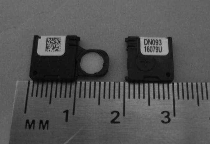
The OSL dosimeters used in this study were InLight nanoDots from Landauer, Inc., as shown in Fig. 1. The dosimeter material is housed in a plastic light-tight casing, measuring 10 × 10 × 2 mm3. The sensitive material, the aluminum oxide doped with carbon, is a 5 mm diameter disk approximately 0.2 mm thick, but thin polyester films on either side of the disk, used for binding, put the total disk thickness near 0.3 mm.16 The disk can slide out of the casing, which is done during reading or bleaching.
Figure 1.
Two Landauer nanoDots. The plastic casing is 1 × 1 × 0.2 cm3, while the dosimeter disk is 5 mm in diameter and 0.3 mm thick. The left dosimeter shows the aluminum oxide exposed.
To read the OSLDs, a microStar OSL reader was used (Landauer, Inc.), which uses CW-OSL for short periods. Although an illumination time of 1 s is common, the reader used in this study illuminated for approximately 7 s per reading. The only difference was an increase in total observed signal and was not expected to affect the results. The reader functions by stimulating the dosimeter with light from LEDs passing through a high band-pass filter.16 The luminescent light is detected with a photomultiplier tube and band-pass filters in front to discriminate between the stimulation and luminescence photons.6 The photomultiplier tube counts were recorded and compared to determine the relative response of different OSLD exposures. After each irradiation, the dosimeter group was read in one session to reduce reader uncertainty. Each dosimeter was read three times consecutively to reduce the measurement uncertainty. The apparent reading of each individual dosimeter was taken as the average of the three readings performed on it consecutively. The average of each dosimeter group was then reported, with error bars representing the coefficient of variation of the readings, which is the ratio of the standard deviation and the average dosimeter readings of each irradiated dosimeter group. Each reading of the dosimeter reduces the total signal by a small amount (∼0.1%), and since all dosimeters were read the same way the same number of times, no depletion correction was used. After being irradiated and read, dosimeters were then optically bleached to remove the remaining signal by putting them in a cabinet with four florescent lights with a UV filter for 24 h. After optical bleaching, the dosimeters were read to measure residual signal. While not all signal can be removed optically,11, 18 the measured residual signal did not change with accumulated dose within the measurement uncertainty.
The sensitivities of the OSLDs themselves were determined prior to the experiments of this study by irradiating them as one group to 25 cGy in cobalt-60. The dosimeters were then read out in a single session and the ratio of the response of an individual dosimeter to the average of the group was used as the sensitivity factor for each dosimeter throughout the remainder of the study. Most sensitivity factors ranged from 0.95 to 1.05. This method differs from other work using just one sensitivity factor for a given dosimeter batch.15 Sensitivity of the dosimeter has been shown not to change significantly at cumulative doses below 10 Gy.11, 12, 19 Even so, the experiments were performed in such a way as to keep the cumulative dose as even as possible amongst the dosimeters to eliminate such uncertainties. No dosimeter received a cumulative dose over 10 Gy.
In addition to the OSL dosimeters, cylindrical polystyrene capsules filled with approximately 20 mg of LiF:Mg,Ti (TLD-100) powder (Quantaflux, Dayton, OH) were also used in this study. This was done to compare to the OSLDs and confirm the angular dependence results. These TLD were read by the Radiological Physics Center (RPC), which has a long history of TLD use.20, 21
Photon measurements
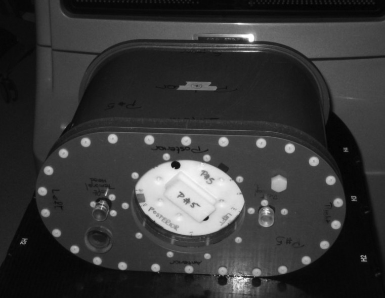
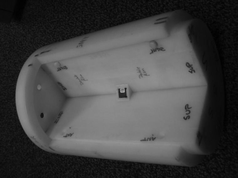
The angular dependence of the nanoDot was first examined in the 6 and 18 MV photon beams of a Varian 21EX linear accelerator (Varian Medical Systems, Palo Alto, CA) that were calibrated according to the TG-51 protocol.22 The detectors were positioned at a depth of approximately 10 cm in a phantom from the RPC. The phantom measured approximately 38(L) × 20(W) × 28(H) cm3 (Fig. 2). This phantom has been shown to provide accurate and reproducible results using TLDs in photon beams.23 The phantom’s outer shell is composed of polystyrene and is hollow; the shell is filled with water at the time of irradiation. The inner section is a homogenous cylinder made of high-impact polystyrene that fits into the outer shell. This insert is composed of equal-sized quarters that hold two dosimeters, each 8 mm away from the center of rotation, as shown in Fig. 3. The cylinder is rotatable to any degree without moving the outer shell or changing the position of the linear accelerator, making it well-suited to study the angular response of the detector.
Figure 2.
Radiological Physics Center phantom measuring approximately 38(L) × 20(W) × 28(H) cm3. The center cylinder rotates within the larger structure to allow irradiation at any angle without moving the setup.
Figure 3.
Inner cylinder of the anthropomorphic phantom, with one quarter removed for dosimeter visualization. The cylinder can hold two dosimeters at a time, each equally spaced 8 mm from the central axis of rotation.
The irradiation measurements were done on the linear accelerator with a gantry angle of 0° and a 10 × 10 cm2 field. The beam was centered on the top, flat portion of the phantom, and the center of rotation of the inner cylinder was along the beam central axis. The surface of the phantom was set to 90 cm source-to-surface distance (SSD). At each investigated angle, three pairs of OSLDs were irradiated in the 6 MV beams and two pairs were irradiated in the 18 MV beams. An average of 100 cGy was delivered to the dosimeters for all irradiations.
Because each dosimeter is offset from the exact center of the rotating cylinder by 8 mm, owing to physical phantom constraints, the dose to each dosimeter varied slightly depending upon the angle. However, because this offset is small and symmetric between the two dosimeters, the average of the two readings represented the dose received at the center. To verify this, computed tomography images of the phantom were used to calculate the dose at the dosimeters at each angle examined in a Pinnacle3 treatment planning system (Philips Medical Systems, Andover, MA). The average of the calculated doses at the two OSLD locations was compared with the point dose at the center of rotation at all angles and was found to agree within 0.4%, indicating that the dosimeter offset could be accounted for by averaging the signal from the two OSLDs.
Because the initial photon measurements described above unexpectedly resulted in an observed angular dependence, additional separate photon measurements were made. First, measurements under the same conditions were repeated at the cardinal angles for the 6 and 18 MV beams on a separate date. This tested the consistency of our results. Second, following the same procedure and using the same phantom as for the OSLDs, the cylindrical TLDs were also irradiated. The TLD powder was housed in a cylindrical capsule and, thus, did not have an angular dependence. The TLD irradiation experiment evaluated whether the phantom contributed to the angular dependence measured by the OSLDs.
Monte Carlo simulations
In order to elucidate the source of the observed photon angular dependence results, the program Monte Carlo N-Particle eXtended (MCNPX, version 2.6; Los Alamos National Laboratory, Los Alamos, NM)24 was used to simulate the 6 MV experimental set up. This program utilized a detailed model of a Varian Clinac 2100 that has been previously benchmarked.25 This model begins tracking with electrons incident on a bremsstrahlung target and incorporates all important beam-line components, including the flattening filter, collimators, and multileaf collimator. The nanoDot detector was simulated inside a 60(L) × 60(W) × 30(D) cm3water tank at 100 cm SSD with a field size of 10 × 10 cm2.
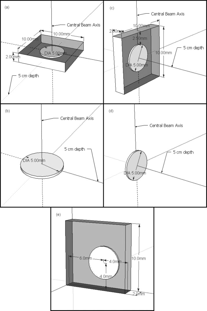
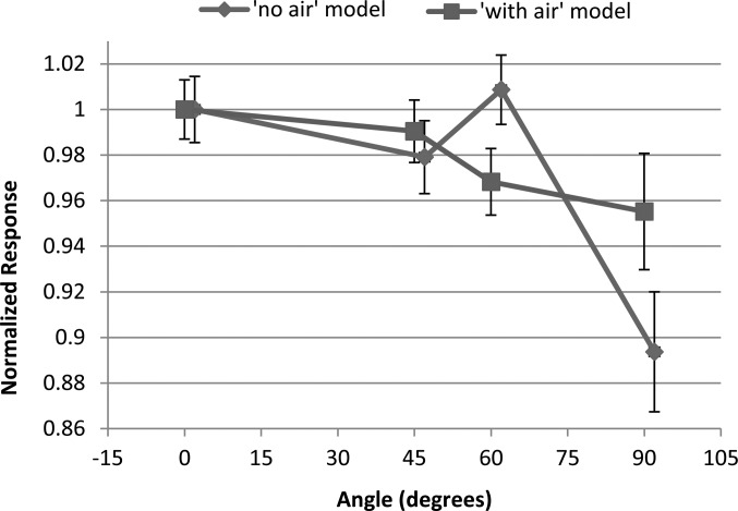
The Monte Carlo model of the nanoDot is shown in Figs. 4a, 4c. The model consisted of a 5 mm diameter disk of Al2O3, 0.2 mm thick, surrounded by 0.05 mm thick polyester binding foils and an air cavity as is present in the actual dosimeter (the “with-air” model). Because the plastic casing of the dosimeter is geometrically complex and nearly water equivalent (1.03 g∕cm3), it was neglected in the model. A build up value of 0.037 g∕cm2 has been reported,11 but this only pertains to the sleeve above and below the disk, not to the sides, where the plastic has other layers. Thus, a simple shell with the same characteristics would not be accurate. The simulated detector was positioned at 5 cm depth in the water tank along the central axis, and at angles of 0°, 45°, 60°, and 90° from the plane normal to the beam central axis (rotating the detector about its center).
Figure 4.
Diagrams of the detector models used for the Monte Carlo simulations. (a) The with-air model at 0°, (b) the no-air model at 0°, (c) the with-air model at 90°, (d) the no-air model at 90°, and (e) a slightly more accurate representation of where the disk is positioned in the nanoDot.
Dose from electrons was calculated over the aluminum oxide disk volume (using an F6 tally24). In addition to the total dose, the dose contributions from ranges of electron energies were also considered, that is, the dose contribution from electrons between energies of 0–0.5 MeV, 0.5–1 MeV, etc. To minimize uncertainties, a large number of histories were run (2 × 10⁹) and weight windows were used.
To examine the possibility that the air cavity contributed to the observed angular dependence, a second Monte Carlo model of the detector was created. This second model was simply the Al2O3 disk surrounded by water, excluding the air cavity and binding foils, (the “no-air” model), and is shown in Figs. 4b, 4d. Identical angular dependence simulations were conducted with this second model.
Proton measurements
The conditions used for irradiations of the nanoDot dosimeters in protons were similar to those used in photons. The irradiations were done at the MD Anderson Cancer Center Proton Therapy Center in the passively scattered beam of the Hitachi ProBeat system. The 200 MeV beam with a 19 cm distal 90% range was used, along with a 10 cm spread-out Bragg peak (SOBP) and 10 × 10 cm2 field. The proton beam was calibrated using the IAEA TRS-398 protocol.26, 27 The detectors were placed within the RPC phantom at the beam isocenter and rotated using the cylinder. The gantry was placed at 0° for all irradiations. Because the 200 MeV beam has a distal 90% range of 19 cm, and the phantom surface to dosimeter depth is 10 cm, 4 cm of buildup was placed on top of the phantom, so that the detectors were located in the center of the 10 cm SOBP. Each irradiation delivered 100 cGy to the dosimeters.
RESULTS
Photon results
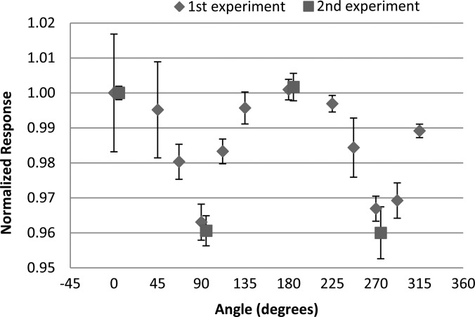
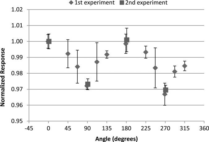
The measured angular dependence of the nanoDot for the initial and repeated irradiations with the 6 MV photon beam is shown in Fig. 5. Results are similarly shown in Fig. 6 for the initial and repeated irradiations with the 18 MV photon beam. The results were normalized to the response at 0°, where 0° corresponds to the dosimeter disk being perpendicular to the incoming radiation beam. The data show that at 90° and 270° (edge-on irradiation) the response is reduced by approximately 4% for the 6 MV beam and 3% for the 18 MV beam. For both energies the results were consistent between the initial and repeated irradiations. Error bars in all experimental measurements represent the coefficient of variation of the dosimeter readings within the respective group. The final reading of each individual dosimeter was taken to be the average of the three consecutive readings.
Figure 5.
The angular dependence results of the nanoDot measured in a 6 MV beam normalized to the response at 0°. Data from the second experiment are slightly offset in the x-direction for visualization. Error bars represent the coefficient of variation of the measured data of each dosimeter group at the respective angle.
Figure 6.
The angular dependence results of the nanoDot dosimeter measured in an 18 MV beam normalized to the response at 0° Data from the second experiment are slightly offset in the x-direction for visualization. Error bars represent the coefficient of variation of the measured data of each dosimeter group at the respective angle.
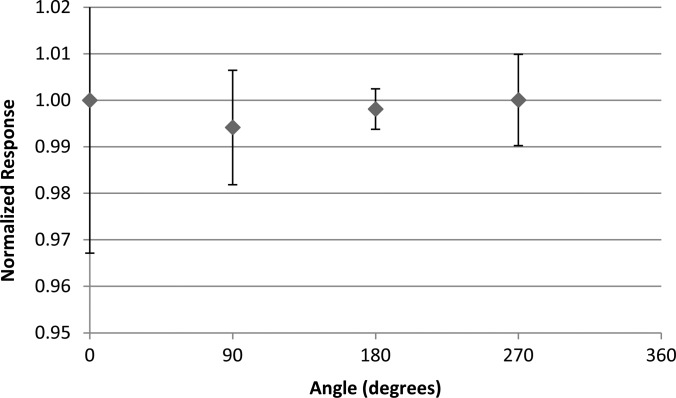
Because this result was different from the result in a previous study,11 we further examined the observed anisotropy. To determine whether the experimental results were affected by possible phantom heterogeneities or geometrical setup differences, the TLDs were irradiated within the phantom in the 6 MV beam in place of the OSLDs. The TLD results are shown in Fig. 7. The TLD readings showed no variation in the response with angle within the uncertainty of the reading, suggesting that the phantom did not contribute to the observed angular dependence of the nanoDot, rather that it arises because of the casing and air gap or the aluminum oxide disk.
Figure 7.
The angular dependence results measured in a 6-MV beam using cylindrical capsule TLDs rather than OSLDs in the anthropomorphic phantom irradiated at the cardinal angles.
Monte Carlo results
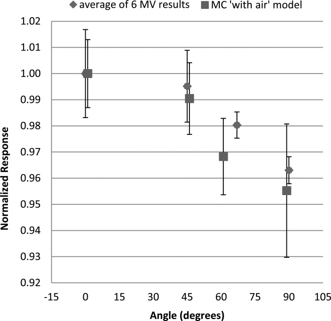
Given the unexpected results of the photon irradiations, Monte Carlo simulations were run using MCNPX to compare to the experimental results and to determine the cause of the angular dependence. Relative dose results from the simulations as a function of dosimeter angle for the four angles tested are compared to the experimental results, shown in Fig. 8. As with the experimental measurements, the results are normalized to the dose absorbed by the aluminum oxide disk at 0° (perpendicular to the incoming beam). Good agreement was seen in the angular dependence predicted by the Monte Carlo simulations and the experimental measurements. Uncertainty for the with-air simulations was given by MCNPX, with an average value of ±1.7%.
Figure 8.
Data from the Monte Carlo simulation of the with air model overlaid with the averaged results of the 6 MV experimental measurements, each normalized to the 0° response of the respective data sets. The MCNPX data are slightly offset in the x-direction for visualization.
The impact of the air cavity was next considered. The angular dependence of the with-air model and no-air model is compared in Fig. 9. For both OSLD models, a nontrivial angular dependence was observed, with a reduced response at 90°. There was a difference between the response with and without an air gap; accounting for the air gap actually reduced the angular dependence relative to just water, making the response more consistent with the measurements. This suggests that the air gap, if anything, actually mitigates the angular dependence associated with the geometry of the aluminum oxide disk. Average uncertainty of the no-air model simulations was ±1.8%.
Figure 9.
Results of the Monte Carlo simulations using models with and without an air gap, showing the angular dependence in a 6 MV beam. The results were normalized to the response at 0°. Error bars represent the stated MCNPX uncertainty in the calculations.
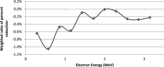
A more detailed study of the results was conducted with MCNPX using the with-air model. The 0° and 90° OSLD orientations were compared in terms of the relative dose deposition for different electron energies. Figure 10 shows the relative amount of electron dose absorbed within the aluminum oxide at 90° relative to 0°. The doses were binned according to the electron energy, and each bin was normalized according to the total absorbed dose for that bin at the 0° orientation (as >98% of total dose for all cases is contributed by electrons with 3 MeV or less, only those energies are shown). A difference was found with the detector parallel to the beam (90°), where there was a reduction in the dose deposited by low-energy electrons. Although there was no significance in any particular energy bin, the overall trend nevertheless suggests a partial volume effect, where low energy electrons are able to deposit dose throughout the OSLD when it faces the incoming radiation and is only 0.2 mm thick. However, when the OSLD is edge-on, the low energy electrons are not able to penetrate the disk, and therefore contribute less dose the crystal.
Figure 10.
Monte Carlo simulation results showing the dose deposition in the aluminum oxide disk for various electron energies when it is at 90°,compared with the dose at 0°. Cumulative dose response compared to 0° is the sum of the bin values (-4.47%).
Proton results
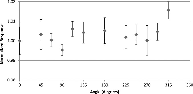
Results of the nanoDot response to proton irradiations are shown in Fig. 11. The relative response at each angle remained nearly constant. Although the response at 315° was higher than the rest, neither its reciprocal angle (135°) nor any other angle showed a similar response, suggesting that this was an anomaly. Thus, no angular trend was seen in the proton response.
Figure 11.
The angular dependence results using the anthropomorphic phantom taken in the center of a 10 cm SOBP in a passively scattered 200 MeV proton beam. Results are normalized to the response at 0°. Error bars represent the coefficient of variation of the measured data of each dosimeter group at the respective angle.
DISCUSSION
Experiments in a phantom showed an angular dependence in the response of the nanoDot to 6 and 18 MV photon beams. Several additional experiments were conducted to verify the validity of these results, and to elucidate the cause of this angular dependence.
Validity of the results was obtained by repeating the experiments. Also, the phantom used for irradiation of the OSLDs was shown to not contribute to the observed angular dependence through TLD irradiations under identical conditions that showed no angular dependence. Monte Carlo simulations were also run and showed a comparable angular dependence to the measured data.
The cause of the angular dependence was primarily attributed to the geometry of the nanoDot. This is shown in Fig. 10, depicting energy-binned electron dose data with a drop in the absorbed dose from low energy electrons. These results show that low energy electrons are able to deposit more dose when the OSL disk is perpendicular to the beam, but do not contribute as much relative dose when the disk is parallel with the primary beam. When the aluminum oxide disk is parallel to the incoming radiation beam, the fluence of primary photons through the disk is reduced. Thus, the significant portion of the absorbed dose comes from scattered photons and large-angle Compton electrons. The stopping power ratio of aluminum oxide relative to water becomes lower with decreasing electron energy. Thus, lower energy Compton electrons hitting the dosimeter from the side in an edge-on geometry would deposit less dose compared to the higher energy electrons hitting the dosimeter straight on or at small angles in a perpendicular geometry. In this manner, the aluminum oxide could experience some partial volume irradiation.
In addition to the impact of the geometry of the dosimeter disk, the Monte Carlo simulations also studied the impact of the air gap surrounding the disk. The angular dependence was reduced with the presence of the air gap. The air gap would be expected to induce effects according to two competing factors. When an air gap surrounds the aluminum oxide fewer photons interact within the air cavity as compared to being surrounded by water, which reduces the number of Compton-scattered electrons created that might deposit dose in the aluminum oxide. However, the reduced stopping power within an air gap will allow a number of electrons entering from outside the cavity to reach the material that would otherwise be stopped by surrounding water. It appears that the latter factor is more important, and therefore the angular dependence is reduced when the air gap is present. Again, it is emphasized that the error bars in all experimental measurements represent the coefficient of variation of the dosimeter readings within the respective group. Measurements were not converted to absolute dose considering the other correction factors that have inherent uncertainties; e.g., energy dependence, absolute reader sensitivity, etc.12, 13, 14, 15 Inclusion of this would introduce unnecessary uncertainty that this study did not attempt to address; however, a facility using an OSL system would need to characterize these basic factors to reduce uncertainty in converting the OSLD measurement to an absorbed dose.
The observed angular dependence may be important for a wide range of applications of the OSLD, which include skin dose measurements on patients and patient treatment field dosimetry QA tests, specifically for multifield treatments where some beams could be at an angle at or near perpendicular to the dosimeter. The findings of this study do not exclude the nanoDot from being used for the aforementioned applications, especially considering the advantages of OSL, but do require that angular dependence be accounted for in dose formalism or avoided in applicable situations.
There were some small differences between the experimental setup and Monte Carlo simulations, such as rectangular water tank phantom versus an oval phantom, as well as dosimeter offset in the pelvic phantom. However, both the tank and phantom are large enough to create electronic equilibrium and scattered photon equilibrium at the dosimeter location. The dosimeters in the experiments and simulations were located at depths of 10 and 5 cm, respectively, although dosimeter response has been shown not to deviate significantly at these depths compared to ion chambers.13 As well, both the MCNPX model and RPC phantom have been validated elsewhere.23, 25 For each MCNPX simulation, the aluminum oxide disk was centered within the air gap while the nanoDot holds the material slightly offset from center, shown in Fig. 4e. While the offset was not investigated, the experimental response did not show large differences between reciprocal angles (0° and 180°, 90° and 270°, etc.), wherein the disk would be shifted to either side of the casing edge by ∼1 mm. Also, because of the complex geometry, the plastic casing of the nanoDot was not incorporated into the simulation. These issues are believed to be negligible because of the agreement between Monte Carlo simulated results and measured response as a function of dosimeter angle (Fig. 8).
The 6 MV photon data of this study disagree with data published by Jursinic, which showed no angular dependence of the dosimeter, within an experimental uncertainty of 0.9%.11 The reasons for the discrepancy are unclear. Jursinic used an older model of the Landauer OSLD, the microDot, which could contribute to the lack of angular dependence observed by Jursinic. However, the general geometry, construction, and casing material are similar to the nanoDot. The microDot measures 24 × 12 × 2 mm3 with the aluminum oxide disk having 7 mm diameter. If anything, this should increase the angular dependence. In addition to the dosimeter, the phantom used in the study by Jursinic was much smaller than the one used in this study, although in both cases, the gantry was stationary while the phantom rotated.
Regardless, from this current experiment, both the experimental and MCNPX data suggest a nontrivial angular dependence for situations where the dosimeter is perpendicular or nearly perpendicular to the incoming photon beam.
The OSLDs were not observed to have an angular dependence in protons, although this was only measured for a specific situation. A large SOBP was used, so by definition there was little dose difference within the volume of interest. Considering the relatively straight path of protons compared to electrons, at least in the middle of the SOBP, angular dependence was not expected. For regions with high linear energy transfer (LET) or rapid change in LET (e.g., the end of the beam path or small SOBPs) this result may not hold true. Although this work elucidated the angular response of the OSLDs in proton beams, there are many unanswered questions remaining about the relationship between OSLDs and proton therapy. For example, there was no investigation of the effect of the dosimeter on different clinical proton energies. Since aluminum oxide has a density of 3.96 g∕cm3, it is possible that the protons passing through the material experience a shift in energy and therefore range in the patient. Also, we did not investigate the relationship of LET at the dosimeter locations, which is known to have an effect on the response.12, 28, 29, 30 However, within the center portion of the SOBP, the LET does not change dramatically.7 The results were relative and, thus, the effect of LET did not affect the findings.
CONCLUSION
This study investigated the angular dependence of OSLDs, specifically the nanoDot from Landauer, Inc. Experimental results with a Radiation Physics Center phantom showed that when the nanoDot dosimeter is edge-on relative to an incoming 6 or 18 MV photon beam, the response is reduced by approximately 4 and 3%, respectively. Monte Carlo simulations using MCNPX suggested that this angular dependence was the result of both an air gap and self-shielding of the dosimeter from low-energy electrons, causing partial volume irradiation. No angular dependence was observed for 200 MeV proton beam irradiations within a 10 cm SOBP. Thus, for photon beams, this may have a clinical impact when beams are incident on the OSLD from extreme angles, such as in skin dose measurements in breast or head and neck irradiations.
ACKNOWLEDGMENTS
The authors would like to thank Jennifer Johnson for the generous beam time and support of the manuscript, RPC staff, including Lynda McDonald for the cobalt-60 irradiations, and Kate Newberry for the manuscript suggestions. Eduardo Yukihara and Gabriel Sawakuchi were also very supportive throughout the experimental process. Although no financial support was given by Landauer, the authors would like to thank them for providing the dosimeters used in this study.
References
- Sawakuchi G. O., Yukihara E., McKeever S. W. S., Benton E., Gaza R., Uchihori Y., Yasuda N., and Kitamura H., “Relative optically stimulated luminsecence and thermoluminscence efficiences of Al2O3:C dosimeters to heavy charged particles with energies relavent to space and radiotherapy dosimetry,” J. Appl. Phys. 104, 124903 (2008). 10.1063/1.3041655 [DOI] [Google Scholar]
- G. Yukihara E., Sawakuchi G., Guduru S., McKeever S. W. S., Gaza R., Benton E., Yasuda H., Uchihori Y., and Kitamura H., “Application of the optically stimulated luminescence (OSL) technique in space dosimetry,” Radiat.Meas. 41, 1126–1135 (2006). 10.1016/j.radmeas.2006.05.027 [DOI] [Google Scholar]
- Yukihara E. G., Gasparian P. B., Sawakuchi G., Ruan C., Ahmad S., Kalavagunta C., Clouse W. J., Sahoo N., and Titt U., “Medical applications of optically stimulated lumiescence dosimeters (OSLDs),” Radiat.Meas. 45, 658–662 (2010). 10.1016/j.radmeas.2009.12.034 [DOI] [Google Scholar]
- Polf J. C., Yukihara E. G., Akselrod M. S., and McKeever S. W. S., “Real-time luminescence from Al2O3 fiber dosimeters,” Radiat.Meas. 38, 227–240 (2004). 10.1016/j.radmeas.2003.10.005 [DOI] [Google Scholar]
- Huntley D. J., Godfrey-Smith D. I., and Thewalt M. L. W., “Optical dating of sediments,” Nature (London) 313x(10), 105–107 (1985). 10.1038/313105a0 [DOI] [Google Scholar]
- Yukihara E. G. and McKeever S. W. S., Optically Stimulated Luminescence: Fundamentals and Applications (Wiley, New York, 2011). [Google Scholar]
- Yukihara E. G., Gasparian P. B. R., Sawakuchi G. O., Ruan C., Ahmad S., Kalavagunta C., Clouse W. J., Sahoo N., and Titt U., “Medical applications of optically stimulated luminescence dosimeters (OSLDs),” Radiat. Meas. 45(3–6), 658–662 (2010). 10.1016/j.radmeas.2009.12.034 [DOI] [Google Scholar]
- Bøtter-Jensen L., McKeever S. W. S., and Wintle A. G., Optically Stimulated Luminescence Dosimetry (Elsevier, Amsterdam, 2003). [Google Scholar]
- Akselrod M. S. and Kortov V.S., “Thermoluminescent and Exoemission properties of New High-Sensitivity TLD anion-Al2O3:C Crystals,” Radiat. Prot. Dosim. 33, 123–126 (1990). [Google Scholar]
- Akselrod M. S., Kortov V. S., and Gorelova E. A., “Preparation and Properties of Al2O3:C,” Radiat. Prot. Dosim. 47, 159–164 (1993). [Google Scholar]
- Jursinic P. A., “Characterization of optically stimulated luminescent dosimeters, OSLDs, for clinical dosimetric measurements,” Med. Phys. 34(12), 4594–4604 (2007). 10.1118/1.2804555 [DOI] [PubMed] [Google Scholar]
- Reft C. S., “The energy dependence and dose response of a commercial optically stimulated luminescent detector for kilovoltage photon, megavoltage photon, and electron, proton, and carbon beams,” Med. Phys. 36(5), 1690–1699 (2009). 10.1118/1.3097283 [DOI] [PubMed] [Google Scholar]
- Yukihara E. G., Mardirossian G., Mirzasadeghi M., Guduru S., and Ahmad S., “Evaluation of Al2O3:C optically stimulated luminescence (OSL) dosimeters for passive dosimetry of high-energy photon and electron beams in radiotherapy,” Med. Phys. 35(1), 260–269 (2008). 10.1118/1.2816106 [DOI] [PubMed] [Google Scholar]
- Schembri V. and Heijmen B. J., “Optically stimulated luminescence (OSL) of carbon-doped aluminum oxide (Al2O3:C) for film dosimetry in radiotherapy,” Med. Phys. 34, 2113–2118 (2007). 10.1118/1.2737160 [DOI] [PubMed] [Google Scholar]
- Viamonte A., da Rosa L. A., Buckley L. A., Cherpak A., and Cygler J. E., “Radiotherapy dosimetry using a commercial OSL system,” Med. Phys. 35(4), 1261–1266 (2008). 10.1118/1.2841940 [DOI] [PubMed] [Google Scholar]
- Perks C. A., Yahnke C., and Million M., “Medical dosimetry using Optically Stimulated Luminescence dots and microStar readers,” 12th International Congress of the International Radiation Protection Association (2008).
- Perks C. A., Le Roy G., and Prugnaud B., “Introduction of the InLight monitoring service,” Radiat.Prot.Dosim. 125, 220–223 (2007). 10.1093/rpd/ncl126 [DOI] [PubMed] [Google Scholar]
- Umisedo N. K., Yoshimura E. M., Gasparian P. B. R., and Yukihara E. G., “Comparison between blue and green stimulated luminescence of Al2O3:C,” Radiat. Meas. 45(2), 151–156 (2010). 10.1016/j.radmeas.2010.02.001 [DOI] [Google Scholar]
- Yukihara E. G. and McKeever S. W., “Optically stimulated luminescence (OSL) dosimetry in medicine,” Phys. Med. Biol. 53(20), R351–R379 (2008). 10.1088/0031-9155/53/20/R01 [DOI] [PubMed] [Google Scholar]
- Kirby T. H., Hanson W. F., Gastorf R. J., Chu C. H., and R. Shalek J., “Mailable TLD system for photon and electron therapy beams,” Int. J. Radiat. Oncol. Biol. Phys. 12(2), 261–265 (1986). 10.1016/0360-3016(86)90107-0 [DOI] [PubMed] [Google Scholar]
- Kirby T. H., Hanson W. F., and Johnston D. A., “Uncertainty analysis of absorbed dose calculations from thermoluminescence dosimeters,” Med. Phys. 19(6), 1427–1433 (1992). 10.1118/1.596797 [DOI] [PubMed] [Google Scholar]
- Almond P. R., Biggs P. J., Coursey B. M., Hanson W. F., Huq M. S., Nath R., and Rogers D. W., “AAPM’s TG-51 protocol for clinical reference dosimetry of high-energy photon and electron beams,” Med. Phys. 26(9), 1847–1870 (1999). 10.1118/1.598691 [DOI] [PubMed] [Google Scholar]
- Followill D. S., Evans D. R., Cherry C., Molineu A., Fisher G., Hanson W. F., and Ibbott G. S., “Design, development, and implementation of the Radiological Physics Center’s pelvis and thorax anthropomorphic quality assurance phantoms,” Med. Phys. 34, 2070–2076 (2007). 10.1118/1.2737158 [DOI] [PubMed] [Google Scholar]
- Hendricks J. S., McKinney G. W., Fensin M. L., James M. R., Johns R. C., Durkee J. W., Finch J. P., Pelowitz D. B., and Waters L. S., “MCNPX, Version 26E User’s Manual,” LA-UR-07- 6632, 2007.
- Kry S. F., Titt U., Ponisch F., Followill D., Vassiliev O. N., White R. A., Mohan R., and Salehpour M., “A Monte Carlo model for calculating out-of-field dose from a varian 6 MV beam,” Med. Phys. 33(11), 4405–4413 (2006). 10.1118/1.2360013 [DOI] [PubMed] [Google Scholar]
- Sahoo N., Zhu X. R., Arjomandy B., Ciangaru G., Lii M., Amos R., Wu R., and Gillin M., “A procedure for calculation of monitor units for passively scattered proton radiotherapy beams,” Med. Phys. 35(11), 5088–5097 (2008). 10.1118/1.2992055 [DOI] [PubMed] [Google Scholar]
- Andreo P., Burns D. T., Hohlfeld K., Huq M. S., Kanai T., Laitano F., Smyth V., and Vynckier S., “Absorbed dose determination in external beam radiotherapy: An international code of practice for dosimetry based on standards of absorbed dose to wate,” IAEA Technical Report Series No. 398 (2000).
- Edmund J. M., Andersen C. E., and Greilich S., “A track structure model of optically stimulated luminescence from Al2O3:C irradiated with 10-60 MeV protons,” Nucl. Instrum. Methods Phys. Res. B 262, 261–275 (2007). 10.1016/j.nimb.2007.05.025 [DOI] [Google Scholar]
- Sawakuchi G., Yukihara E., McKeever S. W. S., and Benton E., “Overlap of heavy charged particle tracks and the change in shape of optically stimulated luminescence curves of Al2O3:C dosimeters,” Radiat. Meas. 43, 194–198 (2008). 10.1016/j.radmeas.2007.11.030 [DOI] [Google Scholar]
- Yasuda H. and Kobayashi I., “Optically stimulated luminescence from Al2O3:C irradiated with relativistic heavy ions,” Radiat. Prot. Dosim. 95(4), 339–343 (2001). [DOI] [PubMed] [Google Scholar]


