

Abstract
Current diagnosis of organ rejection following transplantation relies on tissue biopsy, which is not ideal due to sampling limitations and risks associated with the invasive procedure. We have previously shown that cellular MRI of iron-oxide labeled immune-cell infiltration can provide a non-invasive measure of rejection status by detecting areas of hypointensity on T2*-weighted images. In the current study, we tested the feasibility of using a fluorine-based cellular tracer agent to detect macrophage accumulation in rodent models of acute allograft rejection by fluorine-19 (19F) MRI and MRS. This study used two rat models of acute rejection, including abdominal heterotopic cardiac transplant and orthotopic kidney transplant models. Following in vivo labeling of monocytes and macrophages with a commercially available agent containing perfluoro-15-crown-5-ether, we observed 19F-signal intensity in the organs experiencing rejection by 19F MRI, and conventional 1H MRI was used for anatomical context. Immunofluorescense and histology confirmed macrophage labeling. These results are consistent with our previous studies and show the complementary nature of the two cellular imaging techniques. With no background signal, 19F MRI/MRS can provide unambiguous detection of fluorine labeled cells, and may be a useful technique for detecting and quantifying rejection grade in patients.
Keywords: Heart Rejection, Kidney Rejection, Magnetic Resonance Imaging, Non-invasive Detection of Graft Rejection
INTRODUCTION
Cellular imaging is an emerging field in magnetic resonance. The ability to non-invasively detect the trafficking and accumulation of different cell types in vivo has broad implications for both a better understanding of biological processes and the clinical diagnosis and treatment of numerous diseases. Imaging the immune response is one area that has particular promise. The immune response plays an important role in numerous pathological conditions, and the development of a robust cellular imaging technique may be broadly applicable across many diseases. Phagocytes, such as macrophages, are readily labeled with a wide variety of MRI detectable agents(1,2), and MRI is an excellent modality for anatomical and functional imaging. It is not limited by field of view, depth, or orientation of the target organ, and provides excellent soft-tissue contrast.
Cellular MRI has the potential to make a significant impact in detecting organ rejection following transplantation(2). Despite advances in donor-recipient matching and immunosuppressive drug maintenance therapies, acute rejection remains a threat for graft loss and patient mortality(3,4). Monitoring the status of a transplanted organ, such as a heart or kidney, relies heavily on tissue biopsy, an invasive procedure with the associated risks of perforation, bleeding, and infection. Additionally, this procedure is far from ideal because only a few small samples from limited areas are used to determine the status of the whole organ. As a result, mismatch between biopsy results and actual organ rejection status can occur(5,6).
Using rodent models of organ rejection, we have been developing non-invasive, MRI-based methods for detecting and staging graft rejection. We have shown that iron-oxide-based MRI contrast agents, such as nanometer-sized dextran-coated ultrasmall superparamagnetic iron-oxide (USPIO) or micron-sized (MPIO) particles, are excellent cellular contrast agents and provide significant T2*-based MRI contrast of macrophage infiltration in models of acute renal rejection(7) as well as acute(8–10) and chronic(11) cardiac rejection in rats. With these agents, macrophages can be labeled in vivo by direct intravenous injection and the degree of image contrast due to iron-oxide-labeled cells correlates well with rejection grade determined by histology.
Although iron-oxide-based cellular imaging is very sensitive, in some cases the hypointense contrast produced can be difficult to unambiguously assign to labeled cells because of intrinsic contrast, image artifacts, or pathologies that also result in negative contrast. Also, hypointense contrast and regions of signal dropout due to the presence of labeled cells can sometimes be difficult to robustly quantify in practice. Because of these limitations, it would be useful to have a cellular imaging agent that provides positive image contrast or positive signal. Moreover, it is desirable that the signal be directly related to the density of the labeled cells rather than indirectly related to the effect of the contrast agent on the nuclear relaxation properties of the surrounding water.
Perfluorocarbon-based emulsions are a class of agents for cellular MRI that have gained attention in recent years (for a recent review see(12)). A key feature of this approach is that once the target cells become labeled, the 19F MRI signal provides a unique marker for cell tracking, with no background signal from the host tissue. The labeled cells can then be placed in their corresponding anatomical context with a conventional 1H image. In this study, we have evaluated the feasibility of using a commercially available 19F-based imaging agent for detecting rejection in rat models of renal and cardiac rejection. The goal of this work was three-fold: (i) to investigate if the 19F-emulsion can be used to label macrophages in vivo by direct intravenous injection; (ii) to determine if in vivo labeling provides sufficient 19F signal for detection of labeled macrophage accumulation at the site of rejection; and (iii) to compare the present findings with those previously obtained using iron-oxide particles as contrast agents.
Methods
Animals
All animals used in this study were male inbred Brown Norway (BN; RT1n) and Dark Agouti (DA; RT1a) rats obtained from Harlan (Indianapolis, IN) with a body weights between 250–280 g. Animal protocols were approved by the Institutional Animal Care and Use Committee of Carnegie Mellon University. All animals received humane care in compliance with the Guide for the Care and Use of Laboratory Animals, published by the NIH.
Transplantation Models
This study used two rat models of acute allograft rejection using DA-to-BN rat transplantation pairs (n=13 for heterotopic heart transplantation, n=5 for orthotopic kidney transplantation). For the heterotopic working heart and lung model, an en bloc donor heart and lung was transplanted to a recipient abdomen. In addition to the native heart, BN-BN transplantation pairs (n=4) served as isograft controls that do not experience organ rejection. The heart transplantation model and surgical procedures are described in detail elsewhere(13). In brief, the superior vena cava of the graft heart was anastomosed to the recipient inferior vena cava and the aorta of the graft heart was anastomosed to the recipient abdominal aorta, with the recipient proximal IVC partially obstructed to increase pre-loading. The recipient does not depend on the graft for survival; therefore, the entire rejection process can be studied through the very end stages of cardiac rejection.
The kidney transplantation procedure is described in detail elsewhere(7). Briefly, a left nephrectomy of the recipients was performed, the graft renal artery and vein were anastomosed to the recipients abdominal aorta and IVC, respectively. The ureter was end-to-end anaostomosed.
At the endpoint of the study, grafts were perfused and fixed in 4% paraformaldehyde for 24 hrs. The organs were then transferred to a phosphate-buffered saline (PBS) and stored at 4 °C for magnetic resonance microscopy (MRM), spectroscopy (MRS) and pathology examinations.
In vivo Immune Cell Labeling
The fluorine cellular tracer agent used in this study, V-Sense (VS-580H), was obtained from Celsense, Inc. (Pittsburgh, PA). This emulsion formulation contains 30% w/v perfluoro-15-crown-5-ether (PCE) and according to the manufacturer, has a droplet diameter of 145 nm. Under general isoflurane anaesthesia, recipients were given a 1 mL i.v. infusion (~3.6 mL/kg) via the tail vein at a rate of 3 mL/hr. Heart transplant recipients were injected on post-operative day (POD) 4 (n=3) or 5 (n=9 allografts and n=3 isografts) and kidney recipients on POD 3 (n=3). These time-points represent mild to moderate rejection grades in these models. One isograft heart transplant recipient was injected on POD 26 and imaged on POD 27. Rats were imaged following the injection and at 24 hrs post-injection. Two heart transplant recipients received a fluorescent co-labeled V-Sense that was prepared just prior to infusion by mixing 1 ml of V-Sense with 4 μl of dialkylcarbocyanine dye (DiI, Molecular probes-Invitrogen, Carlsbad, CA)(14). For comparison with previous work, an additional heart transplant recipients was injected with dextran-coated USPIO. The heart transplant recipient was given 4.5 mg Fe/kg BW of Molday ION (BioPAL, Worchester MA) on POD 5 and imaged on POD 6 (see figure caption for details). Two addition kidney transplant recipients are also shown, and one was given 6 mg Fe/kg BW USPIO, details are described elsewhere(7).
In vivo MRI
In vivo MRI was performed on a Bruker AVANCE 7-T/21-cm system. A 72-mm birdcage coil was used for imaging that had a tuning range spanning 282 to 300 MHz (19F to 1H resonance frequencies, respectively). Rats were intubated and ventilated with 2% isoflurane in a 2:1 O2:N2O gas mixture at 1.0 mL/100 g body weight and 60 bpm. Rectal temperature was maintained at 36.5±1 °C with warm air and subcutaneous needle electrodes were placed on the abdomen to detect the ECG of the transplanted heart (SA Instruments, Stony Brook, NY).
Following pilot and anatomical 1H scans, the RF coil was retuned and reduced-resolution 19F images were collected without changing the animal position. Since the imaging frequencies were centered precisely on the water and 19F PCE resonances, 19F images were co-registered with the anatomical features without image post-processing.
Cardiac transplant recipients were placed in the prone position. Cardiac/respiratory gating was used for both 1H and 19F imaging with an axial plane for a pseudo short-axis view of the transplanted heart. A gradient-recalled echo (GRE) was used for anatomical pilot scans and to observe PCE in circulation, a spin-echo sequence was used to detect PCE in the myocardium (6–8 cm FOV, 256×256 matrix for 1H, TE=5–6 ms, and a 2.5-mm slice thickness, and see figure captions for details on 19F imaging).
Kidney transplant recipients were placed supine and were imaged with a coronal plane bisecting both kidneys. A RARE (rapid acquisition with relaxation enhancement) sequence was used for 1H (7×7 cm FOV, 256×256 matrix, 2-mm slice thickness, RARE factor=4, NA=2). A GRE sequence was used to detect PCE in circulation and the PCE-labeled cells (see figure captions for details).
MRM and MRS
Both 1H and 19F images of graft hearts and kidneys were acquired ex vivo at higher resolution using a Bruker AVANCE DRX 11.7-T micro-imaging system. Organs were placed in PBS containing a small amount of USPIO to spoil the surrounding water signal, and imaged with a spin-echo (TR/TE=1000/7 ms, 1.5-mm slice thickness, 128×128 matrix). 19F images were collected with NA=8 to 512 (see figure captions for imaging details). Separately, whole organs isolated from allograft recipients were subjected to 19F NMR spectroscopy using a sealed tube of TFA as a concentration reference. The ratio of PCE peak integral and TFA peak integral were used to determine the relative concentrations of PCE, the mean ± SD is reported per gram of tissue.
Image Analysis
To measure the extent of macrophage infiltration observed in the allograft and isograft hearts, an analysis of spatial occupation was performed. For each image slice, the area of heart tissue was determined from the 1H image. For these ROIs, pixels in the corresponding 19F images with intensity greater than three standard deviations above the mean of the noise were summed to determine the 19F signal area. A two-tailed student’s t-test was used to compare samples; P<0.05 is considered significant. The signal-to-noise ratio (SNR) values were determined as the average ROI signal intensity divided by the standard deviation of the noise.
Pathological Analysis and Rejection Grade Evaluation
Graft tissues were subjected to hematoxylin and eosin (H&E) staining and immunohistochemical staining with the mouse anti-rat macrophage antibody ED1 (AbD Serotec, Oxford, UK) for macrophage detection. The rejection grade of the grafts was determined histopathologically according to the International Society for Heart and Lung Transplantation (ISHLT) criteria(15). For the allogeneic heart grafts, mild (Grade 1A or B) rejection develops by POD 3.5±1; Grade 2 rejection develops on POD 5.5±1; and moderate to the severe (Grade 3A) rejection develops on POD 6.5±1. Kidney allograft rejection grade was determined according to the Banff classification(16). In this model, mild (Grade 1) rejection develops on POD 3, Grade 2 rejection develops on POD 3.5–4, and severe (Grade 3) rejection develops on POD 4.5–5(7). See references (9,10) and (7) for examples of pathology slides for the heart and kidney allografts, respectively.
Fluorescence Microscopy
Immunofluorescent stainingwas performed on 5-μm sectionsof snap-frozen allograft tissue in which the PCE was co-labeled with DiI. Briefly, tissue sections were incubated with mouse anti-rat ED1 monoclonal antibody for 2 hrs in the dark at room temperature followed by incubation withbiotinylated anti-mouse antibody for 1 hr and then 1 hr incubation with Fluorescein Avidin DCS, FITC (Catalog# A-2011, Vector Laboratories, Burlingame, CA) in the dark. Fluorescence images were obtained using an Olympus Provis AX 70 fluorescence microscope (Olympus America, Melville NY). Sections were examined with dual-channel fluorescence using the FITC channel (495 nm excitation, 515 nm emission) for ED1+ cells and the Cy5 channel (649 nm excitation, 668 nm detection) to detect DiI-labeled PCE.
Blood clearance Half-life
Blood clearance was measured in DA rats (n=3). Rats were given an i.v. injection of 0.5 mL of VS-580H and blood was sampled from the saphenous vein periodically over 5 days. The concentration of the PCE was measured by solution NMR at 470 MHz (Bruker Avance 500) using 6–12 μL samples with a trifluoroacetic acid standard. The time-dependent concentration was fit to a mono-exponential decay to determine the blood clearance rate. Values are reported as the half-life ± one standard deviation.
Results
Cardiac Allograft Rejection
Figure 1 shows images of a transplanted heart following direct i.v. infusion of PCE on POD 5. Figure 1A shows a conventional 1H image. Near the center of the image is a short-axis view of the transplanted heart with the right ventricle (RV) and left ventricle (LV) cavities clearly visible. The dark area around the heart results from air in the digestive system. Below the heart is a reference standard containing a 1:40 dilution of PCE emulsion in PBS. Figure 1B shows a corresponding 19F GRE image collected approximately 2 hrs following PCE infusion. 19F images are shown in pseudo-color (hot-iron scale). This image was collected at a lower resolution (128×48) with signal averaging (NA=96) to detect the dilute 19F nuclei. At this time, the PCE is found mainly in the blood pool (Fig. 1B). In the composite image, one can clearly see that the 19F signal density is found in the RV, LV and major vessels, and not in the myocardial tissue (Fig. 1C). By following the time dependence of vascular 19F signal decay in a naïve DA rat (Fig. 1D), the blood clearance half-life of PCE emulsion was determined to be 9.4 ± 2.6 hrs.
Figure 1.
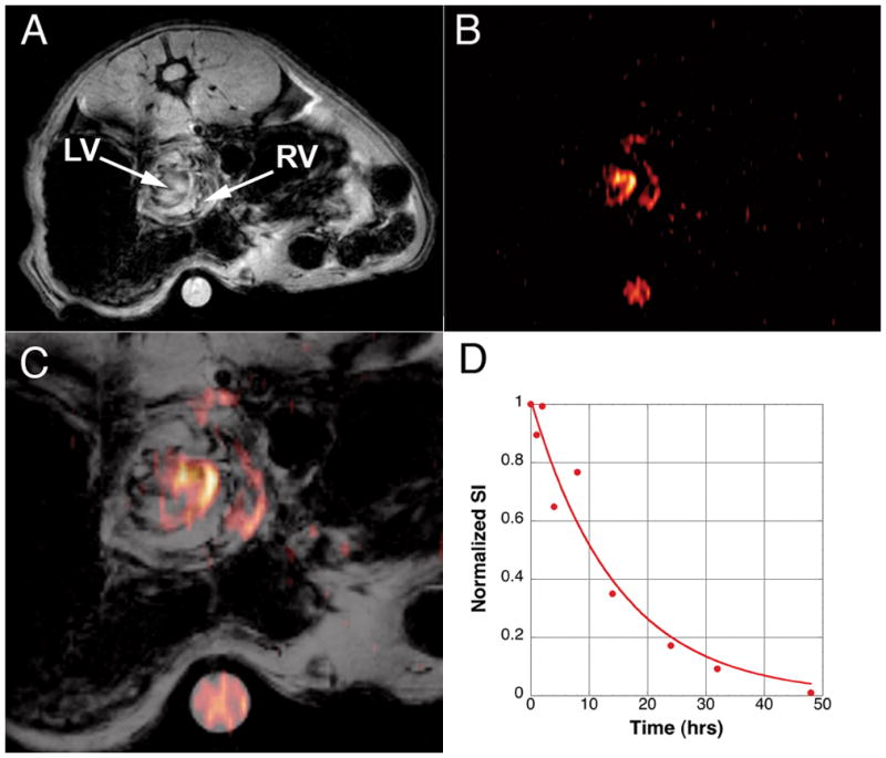
Heterotopic transplantation model imaged approximately 1 hr following PCE injection. Panel A shows a conventional 1H image with respiratory/ECG gating. The graft heart is observed in pseudo short-axis view in the center of the abdomen. Below the rat is a 5 mm tube containing a 1:40 dilution of PCE emulsion. Panel B shows a 19F image rendered in pseudo-color (GRE, 6×6 cm FOV, 128×48 matrix, NA=96). Panel C shows an overlay of the two images. At this early time-point, the 19F density is only observed in circulation in the RV and LV of the heart. Panel D show the decay in 19F signal found by sampling blood from a normal DA rat. The blood-clearance half-life was determined to be 9.4 ± 2.6 hrs.
At 24 hrs after PCE infusion (POD 6), the 19F signal was no longer seen in the LV or RV cavities, but was observed penetrating the myocardium in allograft hearts (Fig. 2A). At POD 6, moderate (Grade 2) rejection is apparent by histology (results not shown). 19F signal in the myocardium was confirmed using ex vivo MRM of the fixed heart, as shown in Figure 2B. The majority of the 19F signal was found near the epicardium, which is consistent with previous studies of iron-oxide-based cellular contrast agents that demonstrated an epicardium to endocardium progression of macrophage infiltration with increasing rejection(9). Figures 2A and 2B show images approximately midway between the apex and base, Figs. 2C and 2D show in vivo and ex vivo images, respectively from the same heart imaged more toward the base. A greater infiltration of 19F signal is found in myocardium at this level. Figure 2E shows an isograft heart treated in a similar manner, only a very low level of 19F signal is observed at the epicardium. However, no 19F signal was detected in the longer-term isograft. Thus, we speculate that the small ‘hot spot’ seen in Figure 2E may be a result of macrophage infiltration in response to ischemic/reperfusion injury from the transplant surgery. For comparison, with previous studies (9,10), figures 2F and 2G show an allograft heart with USPIO-labeled macrophages (in vivo and ex vivo images, respectively). In these T2*-weighted images, labeled macrophage accumulation is observed as areas of hypointensity.
Figure 2.
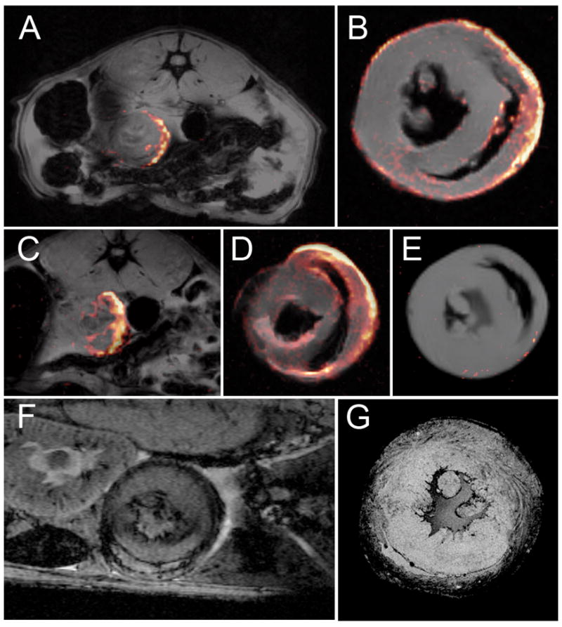
Detection of 19F-labeled macrophage in the myocardium of the transplanted heart graft. Panel A shows a composite 19F/1H image indicating that the PCE is found in the myocardium 24 hrs following injection. The 19F image was collected with respiratory/ECG-gated spin-echo (8×8 cm FOV, 128×128 matrix, NA=4, 2.5-mm slice thickness). Panel B shows an ex vivo composite of the same heart shown in panel A (2.6 cm FOV, 128×128 matrix, NA=8, 1.5 mm slice thickness). Panels C and D show another in vivo and ex vivo image slice of the heart shown in A and B. Panel E shows an isograft heart harvested on POD 6, 24 hrs following PCE injection (parameters same as B, except NA=32). This image has an intensity threshold just at the level of the noise. Panels F and G show examples of T2*-weighted in vivo and ex vivo images, respectively, of POD 6 hearts with USPIO-labeling. (F was collected with a TE= 10 ms 4 cm FOV, 256×256, 1-mm slice thickness, NA=6).
Figures 3A shows an allograft heart imaged on POD5. Only a few small 19F ‘hot spots’ are observed. The 19F signal seen under the graft is likely due to inflammation around the abdominal suture. Figure 3B show another allograft heart on POD 6. In addition to the transplanted organs, Figure 3B clearly shows 19F signal in the liver. Spectroscopic analysis of whole organs showed significant accumulation in the spleen and liver (Fig. 3C), consistent with reticuloendothelial clearance of the PCE emulsion. Allograft hearts harvested on POD 5 and POD 6 have significantly more 19F signal than isograft hearts (P=0.044 and P=0.0047, respectively). In addition, the 19F signal intensity found in the allograft hearts increases for hearts harvested on POD 5 and POD 6 (P=0.0016). Little 19F signal is observed in the native heart or kidneys, with a slightly higher amount in the native lung where a high macrophage population normally exists.
Figure 3.

Distribution of 19F signal intensity. Panel A show an allograft heart imaged on POD 5, and panel B shows another transplant recipient imaged on POD 6. In Panel A only a few small ‘hot spots’ of 19F signal can be seen (6×6 cm FOV, 128 × 66 matrix, NA=32, 2 mm slice thickness). In Panel B 19F signal intensity can also be seen in the liver in addition to the transplanted heart (6 × 6 cm FOV, 128 × 48 matrix, NA=128, 2mm slice thickness). Panel C show the relative mean 19F signal intensity found in harvested tissues for Isografts (n=3), Allografts (Tx Heart) harvested on PODs 5 (n=3) and 6 (n=6). The Native heart (N), Transplanted lung (Tx Lung), Native lung, Spleen, Liver and Kidney were all taken from the POD 6 allograft recipient. Error bars represent standard deviation of the mean. There is a significant difference in signal between isograft and allograft hearts harvested PODs 5 and 6, and a significant difference between allografts harvested on POD 5 and POD 6 (see text).
Previous studies with USPIO labeling of macrophages showed that areas of hypointensity in T2*-weighted images correlated with rejection grade (10). Consistent with the integrated signal, the area of 19F infiltration was highest in the allograft hearts harvested on POD 6 (22.56 ± 8.46%). This is significantly different than POD 5 harvested allografts (5.2 ± 2.36%) and isograft hearts (1.34 ± 0.76%), P=0.0078 and P=0.0047, respectively. The POD 5 harvested hearts did not meet the conventional criteria for statistical significance (P=0.093) compared with isograft hearts, however, this is an unfair comparison since the isografts were imaged with a factor of 2 greater SNR because the signal averaging was different (NA=32 compared with NA=8 for the POD 5 and POD 6 harvested allografts).
Further analysis of the ex vivo images of the allografts reveals an increased infiltration area from the apex to the base of the heart, Figures 4B-4J show a representative image stack of a POD 6 harvested heart. Figure 4K shows a plot of both the area of 19F signal infiltration and the relative signal integral for each slice. The integral of the signal is a measure of the amount of 19F compound present which can be correlated to the number of labeled macrophages in the tissue, but more importantly, it indicates the severity of rejection. Since we currently do not know in vivo labeling efficiency, we did not attempt to quantify the density of macrophages in the graft.
Figure 4.

Representative data for 19F infiltration in the allograft hearts. Panel A show the relative position for images shown in Panels B-J (images slices from the apex to base). Panel K is a plot of both the percent area of 19F-labeled macrophage infiltration and 19F signal integral as a function of slice position. The signal integral was normalized to the maximum % area.
To confirm that 19F-labeled macrophages produced the 19F signal intensity found in the myocardium, we gave two animals a PCE infusion prepared with a DiI fluorescent co-label. Resulting myocardial tissue samples were subjected to anti-ED1 fluorescent staining. Figure 5 shows a dual-channel fluorescence image showing green ED1+ cells (Fig. 5A) and red DiI (Fig. 5B). An overlay of the two images (Fig. 5C) indicates that the PCE-DiI largely correlates with ED1+ macrophages.
Figure 5.
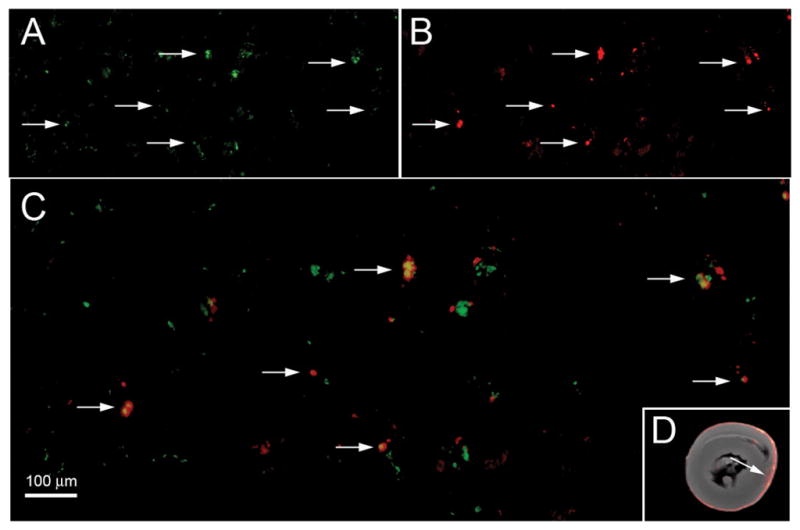
Dual-channel fluorescence microscopy showing co-localization of DiI-PCE and macrophage in the heart graft. Panel A shows a FITC (green) fluorescence for ED1+ cells, (B) shows DiI (red) fluorescence from DiI-PCE, and (C) is an overlay of the two images showing yellow for co-localization of ED1+ cells and DiI-PCE (200× magnification). The scale bar represents 100 μm. Panel D shows the corresponding MRM image and the arrow indicated the approximate location where the fluorescence images were taken.
Kidney Allograft Rejection
Kidney transplant recipients underwent a similar protocol as the cardiac transplant subjects, with the exception that the PCE was infused on POD 3. The kidneys were imaged in a coronal plane bisecting both kidneys. Figure 6A shows 1H and 19F images approximately 2 hrs after the PCE infusion. At this time, the 19F signal was found mainly in circulation, such as the IVC, abdominal aorta, as well as in the common Iliac arteries and veins. A small and roughly equal 19F signal intensity was found in both the native (upper) and transplant (lower) kidneys. At 24 hrs post-injection (POD 4), the transplanted kidney experiences moderate (Grade 2) rejection(7). Figure 4B clearly shows 19F signal intensity outlining the cortex of the transplanted kidney, and no 19F signal was detected in the native kidney. A histogram (Fig. 6C) shows that the signal obtained from macrophage infiltration in allograft kidney is clearly distinguished from noise. We also observed 19F signal distributed over other organs including the spleen and liver (Fig. 6B), consistent with PCE clearance. For comparison, T2*-weighted imaging reveals hemorrhaging in the medulla on POD 5 (Fig. 6G), this can confound the detection of USPIO- labeld macrophages (Fig. 6e)(7).
Figure 6.

Composite 1H/19F images of an orthotopic kidney transplant recipient. 1H images were collected using a respiratory-gated spin-echo with a 2-mm slice thickness whereas the 19F images were collected with an ungated GRE with a 4-mm slice thickness for improved sensitivity of the dilute 19F signal (TR/TE=300/4 ms, FA=30°, FOV= 7×7 cm, 128×64 matrix, NA=192, TA~1 hr). The images are overlaid and 19F is rendered in pseudo-color. Panel A shows images collected approximately 2 hrs post PCE injection on POD 4, the 19F signal is found in the vasculature and equally in both the native (upper) and graft (lower) kidneys. Panel B shows images collected 24 hrs post PCE injection, the signal intensity is found in the allograft kidney (SNR=5.3), as well as other organs, and is virtually undetectable above the image noise in the native kidney. Panel C shows a histogram comparing the signal found in the transplant kidney and an equal area of noise. For comparison with T2*-weighted imaging, two allograft recipients are shown in Panels D and E and Panels F and G, respectively. Panel D shows an allograft kidney on POD 4 just following an injection of 6 mg/kg BW USPIO, 24 hrs later (Panel F) image darkening can be seen in the cortex and medulla of the allograft kidney. Panel G shows the transplanted kidney on POD 4 just following an injection of saline. Panel F is the same rat imaged on POD 5, image hypointensity due to rejection related hemorrhaging can be observed the medulla.
Ex vivo 19F MRM images collected at higher resolution correlate well with histology and show additional features of the labeled macrophage accumulation in the kidneys. Figure 7A shows the 19F image of an allograft kidney harvested on POD 4, and Figure 7B shows the corresponding 1H image. Two distinct bands of 19F signal intensity are seen in the allograft. The first band follows the contour of the cortex, and the second band corresponds to the medulla, with little signal found in the boundary zone. Figures 7C-E show ED1+ staining for the cortex, base of the medullary pyramids, and medulla, respectively. The banded pattern observed with 19F signal clearly correlates with macrophage infiltration in the rejecting graft. Figure 7F shows the native kidney harvested from the same rat as the allograft shown in Figure 7A. While the 19F/1H composite image indicates the presence of 19F-labeled macrophages in the medulla of the native kidney, a significant amount of signal averaging was necessary to detect this feature; 512 echoes were averaged (Fig. 7F), versus 16 for the allograft kidney (Fig. 7A). This signal is likely due to (labeled) macrophages normally found in the vessel endothelium of the kidney(17). Histopathology confirmed only sparse ED1+ cells in the cortex of the native kidney (Fig. 7G), with slightly more found in the epithelium of the minor calices and around the vessels of the medulla (Fig. 7H).
Figure 7.

Ex vivo MRM of kidney allograft correlates with immunostaining for ED1+ cells. Panels A and B show 19F and 1H images of the allograft kidney, respectively, harvested on POD 4, 24 hrs following PCE injection. The 19F image was collected with a 2000/7 ms TR/TE, 3×3 cm FOV, 64×64 matrix, NA=16 and 1.5-mm slice thickness. SNR=4.65 over an ROI containing the cortex and medulla. On Panel B, the labels c, d, and e indicate the approximate locations for images C, D, and E, respectively. For comparison, the native kidney is shown in Panel F. 19F image parameters were the same as Figure 7A, except NA=512 (32 times more than the allograft shown in A). SNR=2.8 in the crescent area containing the 19F signal density. The labels g and h indicate the approximate locations for Panels G and H, respectively. Minimal ED1+ cells are observed in the cortex (Panel G), and the majority of the 19F signal intensity seen in the native kidney appears to be due to macrophages associated with the membranes of the minor calices, shown in H.
The distribution of 19F signal in the allograft kidney became more diffuse as rejection progressed. Figure 8 shows images for another transplant recipient imaged on POD 4 (figs. 8A and 8C) and followed up 48 hrs post PCE injection on POD 5 (figs. 8B and D). The 19F images on POD 4 have features similar to those seen in Figure 6B; the cortex of the kidney is well defined by the 19F signal intensity. On POD 5, the 19F signal is more diffuse throughout the entire kidney. The GRE image in Figure 8D shows that, at this time-point, rejection is becoming severe and hemorrhaging results in endogenous hypointense T2*-weighted contrast in the cortex and medulla.
Figure 8.
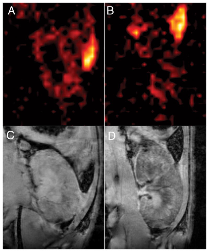
Kidney graft imaged on POD 4 and POD 5. Panels A and B show 19F images of a kidney graft imaged on POD 4 and POD 5, respectively. The 19F images were collected with a RARE sequence, 128×128 matrix, NA=64, 2-mm slice thickness. Panels C and D show corresponding GRE images for images A and B, respectively. Graft enlargement and rejection-related hemorrhaging of the transplanted kidney is observed in D.
Discussion
We used a commercially available formulation of PCE to label and detect macrophage accumulation in two models of organ rejection (heart and kidney) by 19F MRI. Based on this study as well as our previous cellular MRI studies, monitoring macrophage accumulation in the graft appears to be a good biomarker for detecting organ rejection. Furthermore, in vivo labeling of macrophages is simple, does not require cell isolation and monocytes and macrophages will take up a wide variety of agents that may be used for cellular imaging. Our previous studies relied on iron-oxide agents to in vivo label and detect macrophage accumulation by MRI. In this study, we explored the use of a 19F tracer agent to detect the macrophage accumulation at the graft by 19F MRI and MRS.
Metal-ion based contrast agents, such as iron-oxide or gadolinium, and 19F-based cellular imaging agents offer fundamentally different mechanisms of image contrast, having implications on both the ability to detect and quantify labeled cell populations. For metal-based agents, image contrast due to labeled cells relies on detecting the effect of the metal ion on the magnetic resonance relaxation properties (T1, T2, or T2*) of the surrounding water. Iron-oxide-based agents are particularly sensitive because the superparamagnetic iron-oxide generates large local magnetic-field gradients that can be sensed by water molecules that are tens or hundreds of microns from the cell(18,19), magnifying the effect such that even single cells can be imaged in vivo(9,20). This T2*-contrast mechanism, although sensitive has some drawbacks, mainly that image hypointensity can result from sources other than the labeled cells, such as rejection related hemorrhaging observed in medulla allograft kidney (7). Several techniques have been developed for generating positive contrast with iron-oxide cell labeling, such as Inversion Recovery with ON-resonance water suppression (IRON)(21), or to enhance the detectability of iron-oxide labeled cells with phase sensitive techniques(22,23). These techniques, however, may not be broadly applicable because of the necessity for magnetic preparation pulses, or difficulties at tissue interfaces or with certain pathologies where there are inherent magnetic susceptibility and image phase differences.
In contrast to cellular imaging with metal-ion agents, the fluorine agents are directly detected. Since only very low levels of fluorine are typically found in mammals (mainly as fluoride), there is no background signal from which the labeled cells need to be distinguished. This offers the advantage that the signal is highly selective for the labeled cells and not likely to be confused with other pathologies or image artifacts. In our present study, 19F-labeled macrophages were readily imaged in vivo in graft hearts and kidneys experiencing moderate to severe rejection. In these cases, reasonable 19F images could be obtained in 20 to 60 minutes of scan time. Since the 19F label is dilute, detecting very low levels of inflammation may be challenging. Unlike iron-oxide agents were single cells may be tracked at high resolution, the goal with 19F cellular images must be to localize the labeled cells within an anatomical feature. High SNR is not necessary, and an SNR greater than 2–3 is sufficient to distinguish areas of labeled cells from the background noise. Generally a high field magnet should be used, employing sequences and parameters that maximize SNR efficiency. Consideration must also be given to the choice in-plane resolution and slice thickness to maximize the 19F voxel concentration while satisfying the desired anatomical localization. Alternatively, single voxel spectroscopy may be used to detect low levels of inflammation over a whole organ with greater sensitivity.
Quantification remains a challenge for cellular imaging by MRI. This is one area where 19F may be advantageous since the signal intensity can be directly related to a useful index, whereas quantification with metal-ion agents relies on interpretation of relaxation time measurements or comparison of pre- and post-cell accumulation image properties. In the case of iron-oxide agents, quantification can also be limited in areas containing a high concentration of labeled cells, because the range of contrast is limited by the signal being reduced to the level of the noise. We did not explore cell quantification with 19F in our models of transplant rejection because the cell loading was not known. In vivo labeling does not allow for a convenient method to measure the labeling efficiency, as does ex vivo labeling; however, it does offer a simple labeling procedure for potential clinical application. Using in vivo labeling with USPIO and T2*-weighted imaging, we recently showed that the volume of image hypointensity in allograft hearts correlated with rejection status (10). In the current study, we observed that the 19F signal also correlates with rejection status, increasing between POD 5 and POD 6 allograft hearts, corresponding to moderate and severe rejection, respectively. Histology confirms increased infiltration of macrophages between these two time points, however we cannot rule out that some of the 19F signal difference is due to differences in cellular uptake of the 19F agent in vivo. Further investigation with a larger samples sizes and earlier rejection grades will be needed to establish an index of 19F signal and rejection status.
Conclusions
We have shown that macrophages can be labeled in vivo by direct i.v. injection of a commercially available 19F cellular tracer agent, and macrophage accumulation at the site of organ rejection can be detected in vivo by 19F MRI. The present results are consistent with previous studies in these models using iron-oxide cell labeling and T2*-weighted image contrast for detecting macrophage accumulation due to rejection(7–10), and, in many respects, these two techniques can offer complementary information. Iron-oxide agents have high sensitivity at high resolution and 19F offers unambiguous detection and a more easily quantifiable signal.
In conclusion, cellular MRI of in vivo labeled immune cells offers a non-invasive approach to detect and monitor graft rejection after solid organ transplantation. Clinical application of a reliable and non-invasive technique to detect the early signs of graft rejection will improve not only the therapeutic treatment of transplant patients but also improve their quality of life.
Acknowledgments
The authors would like to thank Mrs. Lesley M. Foley for technical assistance, Dr. Yijen L. Wu for helpful discussions, and Mrs. Hongyan Xu and Mrs. Lisa Pusateri for measuring the blood-clearance half-life.
Sources of Funding
This work supported by Grants from the NIH (RO1-HL081349 to Dr. Ho, R01-CA134633, R01-EB003453, and P01-HD047675 to Dr. Ahrens). This work was performed at the Pittsburgh NMR Center for Biomedical Research, an NIBIB National Resource (P41EB-001977).
Disclosures: Eric T. Ahrens is on the Board of Directors and is a shareholder of Celsense. He and Jelena M. Janjic are also paid consultants for Celsense.
References
- 1.Himmelreich U, Dresselaers T. Cell labeling and tracking for experimental models using Magnetic Resonance Imaging. Methods. 2009;48(2):112–124. doi: 10.1016/j.ymeth.2009.03.020. [DOI] [PubMed] [Google Scholar]
- 2.Ho C, Hitchens TK. A non-invasive approach to detecting organ rejection by MRI: monitoring the accumulation of immune cells at the transplanted organ. Curr Pharm Biotechnol. 2004;5(6):551–566. doi: 10.2174/1389201043376535. [DOI] [PubMed] [Google Scholar]
- 3.Knosalla C, Hummel M, Muller J, Grauhan O, Ewert R, Hetzer R. Diagnosis of heart graft rejection. Curr Opin Organ Transplant. 2000;5(2):118–125. [Google Scholar]
- 4.Lindenfeld J, Miller GG, Shakar SF, Zolty R, Lowes BD, Wolfel EE, Mestroni L, Page RL, 2nd, Kobashigawa J. Drug therapy in the heart transplant recipient: part II: immunosuppressive drugs. Circulation. 2004;110(25):3858–3865. doi: 10.1161/01.CIR.0000150332.42276.69. [DOI] [PubMed] [Google Scholar]
- 5.Hummel M, Muller J, Dandel M, Hetzer R. Surveillance biopsies in heart and lung transplantation. Transplant Proc. 2002;34(5):1860–1863. doi: 10.1016/s0041-1345(02)03073-7. [DOI] [PubMed] [Google Scholar]
- 6.Yang HM, Lai CK, Gjertson DW, Baruch-Oren T, Ra SH, Watts W, Wallace WD, Shintaku P, Kobashigawa JA, Fishbein MC. Has the 2004 revision of the International Society of Heart and Lung Transplantation grading system improved the reproducibility of the diagnosis and grading of cardiac transplant rejection? Cardiovasc Pathol. 2009;18(4):198–204. doi: 10.1016/j.carpath.2008.05.003. [DOI] [PubMed] [Google Scholar]
- 7.Ye Q, Yang D, Williams M, Williams DS, Pluempitiwiriyawej C, Moura JM, Ho C. In vivo detection of acute rat renal allograft rejection by MRI with USPIO particles. Kidney Int. 2002;61(3):1124–1135. doi: 10.1046/j.1523-1755.2002.00195.x. [DOI] [PubMed] [Google Scholar]
- 8.Kanno S, Wu YJ, Lee PC, Dodd SJ, Williams M, Griffith BP, Ho C. Macrophage accumulation associated with rat cardiac allograft rejection detected by magnetic resonance imaging with ultrasmall superparamagnetic iron oxide particles. Circulation. 2001;104(8):934–938. doi: 10.1161/hc3401.093148. [DOI] [PubMed] [Google Scholar]
- 9.Wu YL, Ye Q, Foley LM, Hitchens TK, Sato K, Williams JB, Ho C. In situ labeling of immune cells with iron oxide particles: an approach to detect organ rejection by cellular MRI. Proc Natl Acad Sci U S A. 2006;103(6):1852–1857. doi: 10.1073/pnas.0507198103. [DOI] [PMC free article] [PubMed] [Google Scholar]
- 10.Wu YL, Ye Q, Sato K, Foley LM, Hitchens TK, Ho C. Noninvasive evaluation of cardiac allograft rejection by cellular and functional cardiac magnetic resonance. JACC Cardiovasc Imaging. 2009;2(6):731–741. doi: 10.1016/j.jcmg.2009.01.013. [DOI] [PMC free article] [PubMed] [Google Scholar]
- 11.Ye Q, Wu YL, Foley LM, Hitchens TK, Eytan DF, Shirwan H, Ho C. Longitudinal tracking of recipient macrophages in a rat chronic cardiac allograft rejection model with noninvasive magnetic resonance imaging using micrometer-sized paramagnetic iron oxide particles. Circulation. 2008;118(2):149–156. doi: 10.1161/CIRCULATIONAHA.107.746354. [DOI] [PMC free article] [PubMed] [Google Scholar]
- 12.Janjic JM, Ahrens ET. Fluorine-containing nanoemulsions for MRI cell tracking. WIREs Nanomedicine and Nanobiotechnology. 2009;1(5):492–501. doi: 10.1002/wnan.35. [DOI] [PMC free article] [PubMed] [Google Scholar]
- 13.Wu YJ, Sato K, Ye Q, Ho C. MRI investigations of graft rejection following organ transplantation using rodent models. Methods Enzymol. 2004;386:73–105. doi: 10.1016/S0076-6879(04)86003-8. [DOI] [PubMed] [Google Scholar]
- 14.Ahrens ET, Flores R, Xu H, Morel PA. In vivo imaging platform for tracking immunotherapeutic cells. Nat Biotechnol. 2005;23(8):983–987. doi: 10.1038/nbt1121. [DOI] [PubMed] [Google Scholar]
- 15.Winters GL, Marboe CC, Billingham ME. The International Society for Heart and Lung Transplantation grading system for heart transplant biopsy specimens: clarification and commentary. J Heart Lung Transplant. 1998;17(8):754–760. [PubMed] [Google Scholar]
- 16.Racusen LC, Solez K, Colvin RB, Bonsib SM, Castro MC, Cavallo T, Croker BP, Demetris AJ, Drachenberg CB, Fogo AB, Furness P, Gaber LW, Gibson IW, Glotz D, Goldberg JC, Grande J, Halloran PF, Hansen HE, Hartley B, Hayry PJ, Hill CM, Hoffman EO, Hunsicker LG, Lindblad AS, Marcussen N, Mihatsch MJ, Nadasdy T, Nickerson P, Olsen S, Papadimitriou JC, Parmjeet SR, Rayner DC, Roberts I, Rose S, Rush D, Salinas-Madrigal L, Salomon DR, Sund S, Taskinen E, Trpkov K, Yamaguchi Y. The Banff 97 working classification of renal allograft pathology. Kidney Int. 1999;55(2):713–723. doi: 10.1046/j.1523-1755.1999.00299.x. [DOI] [PubMed] [Google Scholar]
- 17.Paul LC, Grothman GT, Benediktsson H, Davidoff A, Rozing J. Macrophage subpopulations in normal and transplanted heart and kidney tissues in the rat. Transplantation. 1992;53(1):157–162. doi: 10.1097/00007890-199201000-00032. [DOI] [PubMed] [Google Scholar]
- 18.Dodd SJ, Williams M, Suhan JP, Williams DS, Koretsky AP, Ho C. Detection of single mammalian cells by high-resolution magnetic resonance imaging. Biophys J. 1999;76(1 Pt 1):103–109. doi: 10.1016/S0006-3495(99)77182-1. [DOI] [PMC free article] [PubMed] [Google Scholar]
- 19.Lauterbur PC, Bernardo ML, Mendonca Dias HM, Hedges LK. Microscopic NMR imaging of the magnetic field around magnetic particles. Proceedings of the 5th Annual Meeting, Magn Reson Med; Montreal, Qubebec Canada. August 12–22 1986. [Google Scholar]
- 20.Shapiro EM, Sharer K, Skrtic S, Koretsky AP. In vivo detection of single cells by MRI. Magn Reson Med. 2006;55(2):242–249. doi: 10.1002/mrm.20718. [DOI] [PubMed] [Google Scholar]
- 21.Stuber M, Gilson WD, Schar M, Kedziorek DA, Hofmann LV, Shah S, Vonken EJ, Bulte JWM, Kraitchman DL. Positive contrast visualization of iron oxide-labeled stem cells using inversion-recovery with ON-Resonant water suppression (IRON) Magnetic Resonance in Medicine. 2007;58(5):1072–1077. doi: 10.1002/mrm.21399. [DOI] [PubMed] [Google Scholar]
- 22.Decrespigny AJ, Roberts TPL, Kucharcyzk J, Moseley ME. Improved Sensitivity to Magnetic-Susceptibility Contrast. Magnetic Resonance in Medicine. 1993;30(1):135–137. doi: 10.1002/mrm.1910300121. [DOI] [PubMed] [Google Scholar]
- 23.Haacke EM, Xu YB, Cheng YCN, Reichenbach JR. Susceptibility weighted imaging (SWI) Magnetic Resonance in Medicine. 2004;52(3):612–618. doi: 10.1002/mrm.20198. [DOI] [PubMed] [Google Scholar]