Abstract
Miniaturization of optical cavities has numerous advantages for enhancing light–matter interaction in quantum optical devices, low-threshold lasers with minimal power consumption, and efficient integration of optoelectronic devices at large scale. However, the realization of a truly nanometer-scale optical cavity is hindered by the diffraction limit of the nature materials. In addition, the scaling of the photon life time with the cavity size significantly reduces the quality factor of small cavities. Here we theoretically present an approach to achieve ultrasmall optical cavities using indefinite medium with hyperbolic dispersion, which allows propagation of electromagnetic waves with wave vectors much larger than those in vacuum enabling extremely small 3D cavity down to (λ/20)3. These cavities exhibit size-independent resonance frequencies and anomalous scaling of quality factors in contrast to the conventional cavities, resulting in nanocavities with both high Q/Vm ratio and broad bandwidth.
Keywords: metamaterials, nanophotonics, nanowires, plasmonics
Optical microcavities and nanocavities having both high-quality factor Q and small modal volume V are known to enhance light–matter interaction, resulting in increased spontaneous emission (1–3), optical nonlinearity (4, 5), strong coupling in quantum electrodynamics (6, 7), and optomechanic effects (8, 9). Although dielectric microcavity designs such as microdisks (10, 11), microposts (1), photonic crystals (12, 13), and metal claddings (14–16) are pushing the cavities to smaller scales, their physical sizes are larger than the wavelength in order to confine photon effectively. Plasmonics offers new capabilities in confining electromagnetic waves to a fraction of their free space wavelength (17). Their unique dispersion relations enable propagation of large wave vectors (ultrashort wavelengths) along the metal–dielectric interfaces, providing the potential to realize nanocavities with subwavelength mode volume. Although plasmonic nanocavity designs have been recently proposed (18, 19), the experimental demonstrations have so far exhibited physical sizes larger than the cubed wavelength (20, 21).
The emergence of metamaterials brought new perspective on how light can be manipulated by artificially designed nanostructures and exhibited optical phenomena such as negative refraction (22–25), cloaking (26–31), and ultrahigh refractive index (32). A unique class of metamaterials is the indefinite medium for which not all the principal elements of the permittivity and/or permeability tensors have the same sign (33). The nonmagnetic design and the off-resonance operation of the indefinite medium significantly reduce the energy loss of electromagnetic waves commonly observed in metamaterials (34). The unique dispersion of such materials allows the strong enhancement of optical density of states (35–37) as well as the observation of broadband negative refractions at indefinite/normal materials interfaces (23).
In this letter, we theoretically propose a unique approach based on indefinite metamaterials for deep subwavelength photon confinement in truly nanoscale cavities in all three dimensions. The indefinite media (for example, the metal nanowire array system (23), as shown in Fig. 1A) allow propagation of waves with very large momentum, introducing a strong mode mismatch between the underlying metamaterial and the surrounding medium (e.g., free space) which results in total internal reflection (TIR). The unique photon confinement mechanism, based on the high-k components in indefinite metamaterials, breaks the limitation of cavity size and allows the realization of nanocavities at deep subwavelength scale with both high Q/V ratio and broad bandwidth.
Fig. 1.
(A) Schematic of the nanowire metamaterial which possesses indefinite permittivity. (B) Isofrequency contours of light with 1.5-μm vacuum wavelength. The inner and outer circles are the contours in air and in silicon respectively. The hyperbola (black curves) is the contour in the indefinite material. (C) Isofrequency contour of the nanowire metamaterial in x-z plane, which is parallel to the nanowires, inside the first BZ defined by the period of nanowire array. Every point on the colorful curves represents an allowed propagating mode inside the bulk metamaterial. The red curve is one branch of the hyperbolic isofrequency contours calculated from effective media approximation. The dotted lines are the theoretical asymptotes of the hyperbola and the yellow circle in the center with radius of k0 represents the isofrequency contour of light in air. The curves from the simulation bend and become flatter close to the BZ boundary due to Bragg diffraction effect. The data were obtained from full wave simulation of the silver nanowire array embedded in Al2O3 matrix at 1-μm wavelength.
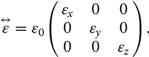
Consider a nonmagnetic uniaxial indefinite material with the permittivity tensor along the principal axes as follows,
 |
[1] |
where the diagonal elements are not all with the same sign. As a simplest example, we assign εx = εy = εv > 0 and εz = εp < 0 (33). Without loss of generality, we first assume ideal lossless metamaterial whose permittivity elements are all real-valued. The dispersion relation of electromagnetic waves in such materials, derived directly from Maxwell’s equations, can be written as
 |
[2] |
where kp is the wave vector component parallel to the optical axis, which is equivalent to kz, and kv is the vector sum of kx and ky, therefore perpendicular to the axis. At a fixed frequency, the allowed propagating k vectors are expressed as an isofrequency contour in the kv-kp plane, showing a hyperbolic curve, as a result of the negative sign of εz. Fig. 1B shows a characteristic isofrequency contour of the propagating light inside materials with indefinite permittivity. In contrast to a closed curve dispersion (circular or elliptic in natural dielectrics) which imposes a tradeoff between kv and kp, the hyperbolic dispersion allows wave vectors with simultaneously large components in all three dimensions. Consequently, very large wave vectors which cannot propagate in air and natural dielectrics can exist in indefinite materials and strong wave confinement is viable. Ideal indefinite media allow the wave vector to be infinitely large with no frequency cutoff for the light propagating in it, though practically it might be limited by the materials loss or the metamaterial characteristic length scales.
Although conventional dielectric cavities are limited by their closed isofrequency contour, the large wave vectors supported in indefinite media with hyperbolic dispersion allow extremely small cavity size for realizing truly nanoscale cavities with the ability to sustain optical modes with volumes much smaller than the cube of their vacuum wavelength. Their ultrahigh wave vectors, corresponding to large effective index of refraction, lead to the formation of nanometers-scale standing wave, whereas the strong momentum mismatch between the wave vectors inside the cavity and those of free space (as apparent from Fig. 1) provides an efficient TIR feedback mechanism.
A cavity mode can be formed when the round-trip phase of optical wave is an integer number of 2π,
| [3] |
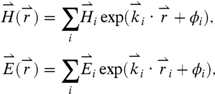
where k is the magnitude of the wave vector, d is the round-trip propagation length, Δφ is the phase shift associated with the reflection, and m is any integer that defines the mode order. Due to the symmetry of the permittivity tensor, it is convenient to consider a tetragonal shaped cavity for further study. Around each vertex of the tetragonal cavity are three mutually perpendicular facets forming a retroreflector that inverts the wave vector of any incoming light. In general, a resonating mode is a superposition of four pairs of oppositely propagating waves in the tetragonal cavity as a result of the four different pairs of retroreflectors formed at the corners of the tetragonal cavity. The magnetic and electric fields are hence expressed by
 |
[4] |
where i is the index for four pairs of optical waves with different orientations, and ϕi represents the phase associated with the ith optical wave. Summing all the reflections yields the electric field distribution. For example,
 |
[5] |
where l, m, and n are integers for the mode orders in three directions, and kx, ky, and kz are wave vector components along the principle axes of the Cardinal coordinate, which are dictated by the hyperbolic isofrequency contour. Similar equations can also be obtained for Ex and Ey components. Eq. 3 relates the physical dimensions of the cavity with the resonating wave vector as follows,
 |
[6] |
where φx, φy, and φz represent the phase shift associated with the TIR at interfaces perpendicular to x, y, and z axes, respectively (38). The anisotropy of the indefinite medium leads to different total internal reflection conditions for different directions of propagation. As shown in Fig. 1B, there is no mode in air that matches kp (the momentum along the optical axis) inside the indefinite material, and hence the side walls of the tetragonal cavity totally reflect the incidence with any allowed incident angles; the critical angle of the top and bottom interfaces is given by  from the condition of kv > k0. Here k0 is the free space wave vector, and εp and εv are the permittivity tensor elements along and perpendicular to the optical axis of indefinite medium, respectively.
The open curved hyperbolic dispersion gives rise to unlimited magnitude of the wave vectors in an ideal indefinite medium, making the physical size of the cavity arbitrarily small. Moreover, the unbounded hyperbolic isofrequency contour results in different effective indices for different modes. Cavities at different sizes made of the same hyperbolic metamaterials could resonate at the same frequency with the same cavity mode order, in contrast to all other photonic cavities, where a change in their size results in a different frequency or different cavity mode.
The concept of hyperbolic medium nanocavity can be realized in the indefinite materials demonstrated in metal nanowire systems (23), shown in Fig. 1A. Such nanowire based indefinite medium is intrinsically low loss over a broad range of wavelength because of its nonmagnetic and off-resonance design. The permittivity tensor elements along (εp) and perpendicular to (εv) the optical axis can be estimated from effective medium approximation by (39, 40)
 |
[7] |
where p is the volume filling ratio of metal, and εm and εd are the permittivities of metal and dielectric, respectively. Fig. 1C shows the dispersion relation obtained from full wave simulation of the propagating modes inside a bulk metamaterial made of silver nanowire array in alumina matrix (Computer Simulation Technology Microwave Studio) that naturally takes into account the band-edge effects at high wave vectors close to the edge of the Brillouin zone (BZ). The wave vector is limited by the structure period where the dispersion curve is bent close to the edge of the first BZ. The red lines represent an ideal hyperbolic medium (i.e., period → 0) where the hyperbolic curve accesses infinitely high wave vectors. It is apparent from Fig. 1C that the effective medium approximation is valid even for wave vectors an order of magnitude larger than that in vacuum, as long as they are not too close to ± π/a given the period a of the nanowires.
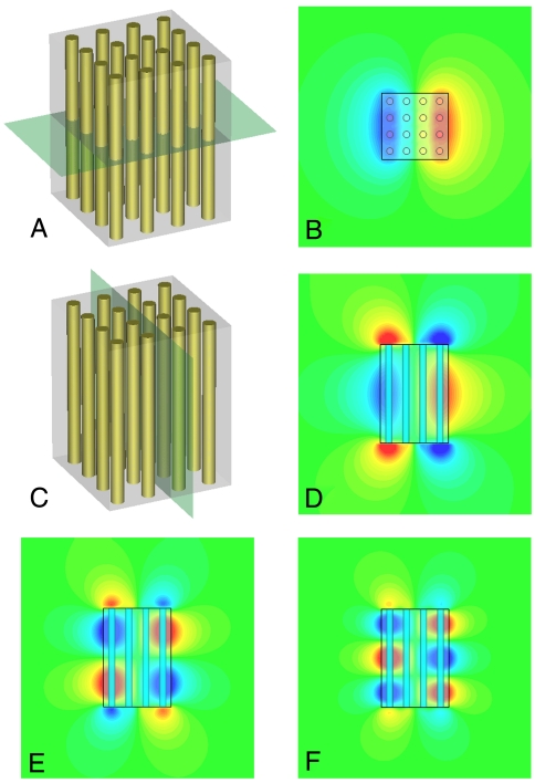
Fig. 2 A and C depict the Ez field distribution cross-sections of the cavity mode of a 80 × 80 × 104 nm nanocavity made of 4 × 4 nanowire array. The silver nanowire array has a pitch of 20 nm and the diameter of each wire is 8 nm. Al2O3 is chosen to be the host dielectric material. Fig. 2 B and D are the field distributions of (2,1,1) mode corresponding to the cross sections in A and C, respectively. Higher order modes like (2,1,2) and (2,1,3) are also shown in Fig. 2 E and F (mode order defined in SI Text). Modes (2,1,1), (2,1,2), and (2,1,3) are resonating at vacuum wavelengths of 1,500, 918, and 750 nm, respectively. The evanescent fields, extended outside the cavity, can be observed.
Fig. 2.
Cross-sectional view of Ez field distribution from full wave simulation results of different orders of modes inside a 3D subwavelength cavity made of indefinite metamaterials. (A) Perspective view of the cavity containing 4 × 4 silver nanowire array. The gray plane across the center of the cavity is where we obtain the field distribution of (2,1,1) mode in B. (C) The same cavity as in A, but the gray plane is parallel to the nanowires and showing where we obtain D)–(F. D–F are (2,1,1), (2,1,2), and (2,1,3) modes of the same cavity, respectively. These modes resonate at different frequencies. The field distributions are shown in false color, with red to blue colors representing positive to negative values.
The resonant modes inside the nanowire cavity do not emerge from the local resonance effect of individual silver nanowire (localized surface plasmon resonance), but are a result of the underlying metamaterial properties, manifested by the fact that the modes are determined by the filling ratio, not the detailed configuration (arrangement) of the nanowires. It is evident that cavities with different nanowire configurations but the same filling ratio show the same resonant modes and field profiles, given that the size of the nanowire and interwire distance are smaller than the wavelength and cavity size (SI Text).
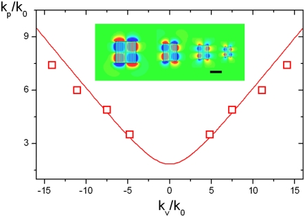
Given the increasing trend in minimizing the size of an optical cavity to enhance light–matter interactions, a variety of deep-subwavelength resonators have been investigated, including nanometer-sized metallic particles (41) and gap plasmon resonators (42). However, the size of a resonator is intimately related to its resonant conditions (resonance frequency and mode numbers). As shown in Fig. 3, nanocavities made of hyperbolic-dispersion metamaterials possess a unique property. Indefinite cavities with substantially different sizes can be designed to resonate at the same frequency and with the same mode order, utilizing the extraordinary indefinite dispersion in such media to naturally select the appropriate effective index of refraction. Distinctive from the localized plasmon resonances in metal nanoparticles much smaller than the exciting wavelength, the electromagnetic oscillation in an indefinite cavity has rapid phase retardation and possesses a verity of cavity modes, whereas, in the metal nanoparticles, the charges move all in phase, which can be described by quasi-static analysis (17). The examples given in Fig. 3 are all resonating with mode order (2,2,2) and at a frequency corresponding to 1.2-μm wavelength in vacuum. The size of the cavities and cavity modes can be scaled down to λ/20, ideally with no limit. Such behavior has never been achieved in any other kind of optical cavities, to our best knowledge, and should open up a new degree of freedom in nanophotonic cavity design. The full wave simulation results are also shown in Fig. 3 for comparison, which are slightly deviated from the theoretical curve at large k values, consistent with the bending of the isofrequency contour close to the BZ boundary.
Fig. 3.
Resonating k values compared to the isofrequency contour of the bulk nanowire metamaterials. The red curve is the hyperbola calculated using effective media approximation. The red squares represent the peak k values obtained by Fourier transform of the field distribution inside cavities at different sizes (lateral length of 360, 240, 180, and 120 nm, respectively). All the cavities are made of the same metamaterials and all resonate at 1.2-μm wavelength. The wave vector in vacuum is represented by k0. (Inset) Modes in cavities with different sizes correspond to the red data points. Modes in smaller cavities correspond to data points with larger k values, respectively. (Scale bar: 200 nm.)
The strong mode confinement associated with large wave vectors in all three dimensions, along with the mode mismatch between the cavity modes and those of free space, results in very low radiation losses because the high-k components cannot couple from bulk indefinite material into air if the interfaces are infinitely large. However, the sharp cavity edges will scatter the optical waves with high k (≫k0) and generate additional k components located in the light cone of air (< k0), which constitute the main radiation loss mechanism. Coupling from plane waves in free space to an indefinite cavity is limited due to the large mismatch of wave vectors; however, evanescent coupling, (for example, through total internal reflections or tapered optical fibers) can significantly increase the coupling efficiency (6).
The quality factor of a cavity can be expressed as  where α represents the energy loss per unit length and is comprised of intrinsic metal loss and radiation loss α = αOhm + αrad, where αOhm and αrad are intensity attenuations based on the material loss and radiation loss, respectively. Let us consider first an ideal indefinite cavity with no metal losses where the energy loss is only due to the radiation of the cavity mode by the edges and can be estimated from k-space field distribution as αrad ∝ k-3 (43). At the same time, the effective index for high-k vectors scales linearly with k, under effective medium approximation, in sharp contrast to natural materials. As a result, the radiation quality factor increases for smaller cavities where higher k modes resonate Qrad ∼ k4 ∼ L-4, where L = V1/3 is the characteristic length of the cavity. The radiation quality factor Qrad of a typical indefinite cavity with a size less than 100 nm in all three dimensions is shown to be greater than 104. For comparison, a metal nanoparticle with the same size and shape can only achieve Qrad of about a few hundred.
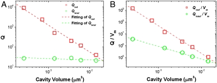
Fig. 4 shows the simulated Qrad values as a function of the cavity size for the (2,1,1) modes resonating at 1.5-μm wavelength for various cavity sizes. The simulation results are consistent with the theoretical predictions of Qrad ∝ k4. Although enhanced quality factor with decreasing device size are consistent with deep subwavelength antennas for telecommunication applications (44), it still stands in sharp contrast to dielectric cavities, where the Q factor is typically proportional to the cavity size, due to the increase in the cavity mode order and resonating frequencies.
Fig. 4.
(A) Quality factor of nanocavities made of the same indefinite media but with different cavity size. The red squares represent the Q values in cavities neglecting the material losses. The green circles are the Q factors obtained in cavities considering full material losses. Fitting of the data gives the behavior of Qrad ∼ k4 ∼ L-4. (B) Q/Vm values neglecting the materials loss (red squares) and considering the material loss (green circles), depending on the size of the indefinite nanocavities, where Vm is the mode volume calculated from simulation results (SI Text).
Whereas ideal nanocavities can obtain high Qrad, a cavity made of actual metal–dielectric nanostructures exhibits nonnegligible metal loss which restricts the overall quality factor. The total Q is determined by both radiation loss and Ohmic loss αrad, αOhm. As the imaginary part of the wave vector scales similarly to its real part in indefinite medium, smaller cavities, while suffering lower radiation loss, will undergo higher intrinsic losses. Consequently, the quality factor remains nearly constant inside the indefinite-medium cavities with different sizes and is limited to about 30 (shown as red dots in Fig. 4A). Nevertheless, the quality factor to mode volume ratio, Q/Vm still increases as the cavity is shrunk, as shown in Fig. 4B, opening the way for applications utilizing strong light–matter interactions. Metallic loss has been one of the major issues that hinder the applications of metamaterials. Gain media have been successfully applied to compensate the metal loss at optical frequencies for a variety of systems (41, 45, 46). By working at the low temperature, the reduction of metal loss and the enhancement of metallic cavity quality factor have been experimentally demonstrated (14, 47).
In conclusion, we have theoretically designed an optical cavity with deep subwavelength size in all three dimensions by using indefinite medium. The hyperbolic dispersion allows access to a large effective index to form optical modes with volumes much smaller than the cube of their vacuum wavelength. The open-curve dispersion also allows the cavities at different sizes to resonate at the same frequency and with the same mode order, which is not observed in conventional photonic cavities. In addition, the large wave vector at the cavity resonance results in strong momentum mismatch between the cavity and free space modes and hence greatly reduces the radiation loss of the cavity. The radiation loss of such nanocavities decreases with the decrease of the cavity size, in stark contrast to conventional photonic cavities. Even when considering the material loss, the indefinite-medium nanocavities provide high Q/Vm ratio, together with a relatively low Q, which indicates strong light–matter interaction over a broad operation bandwidth, paving another avenue to manipulate the light–matter interaction in metamaterials.
Supplementary Material
Acknowledgments.
Authors acknowledge support from Office of Basic Energy Sciences, Materials Sciences Division of the US Department of Energy and Lawrence Berkeley National Laboratory under Contract DE-AC02-05CH11231.
Footnotes
The authors declare no conflict of interest.
This article is a PNAS Direct Submission.
This article contains supporting information online at www.pnas.org/lookup/suppl/doi:10.1073/pnas.1104418108/-/DCSupplemental.
References
- 1.Gérard JM, et al. Enhanced spontaneous emission by quantum boxes in a monolithic optical microcavity. Phys Rev Lett. 1998;81:1110–1113. [Google Scholar]
- 2.Gerard J, Gayral B. Strong Purcell effect for InAs quantum boxes in three-dimensional solid-state microcavities. J Lightwave Technol. 1999;17:2089–2095. [Google Scholar]
- 3.Vuckovic J, Fattal D, Santori C, Solomon GS, Yamamoto Y. Enhanced single-photon emission from a quantum dot in a micropost microcavity. Appl Phys Lett. 2003;82:3596–3598. [Google Scholar]
- 4.Spillane SM, Kippenberg TJ, Vahala KJ. Ultralow-threshold Raman laser using a spherical dielectric microcavity. Nature. 2002;415:621–623. doi: 10.1038/415621a. [DOI] [PubMed] [Google Scholar]
- 5.Ilchenko VS, Savchenkov AA, Matsko AB, Maleki L. Nonlinear optics and crystalline whispering gallery mode cavities. Phys Rev Lett. 2004;92:043903. doi: 10.1103/PhysRevLett.92.043903. [DOI] [PubMed] [Google Scholar]
- 6.Vahala KJ. Optical microcavities. Nature. 2003;424:839–846. doi: 10.1038/nature01939. [DOI] [PubMed] [Google Scholar]
- 7.Hennessy K, et al. Quantum nature of a strongly coupled single quantum dot-cavity system. Nature. 2007;445:896–899. doi: 10.1038/nature05586. [DOI] [PubMed] [Google Scholar]
- 8.Kippenberg TJ, Vahala KJ. Cavity optomechanics: Back-action at the mesoscale. Science. 2008;321:1172–1176. doi: 10.1126/science.1156032. [DOI] [PubMed] [Google Scholar]
- 9.Eichenfield M, Camacho R, Chan J, Vahala KJ, Painter O. A picogram- and nanometre-scale photonic-crystal optomechanical cavity. Nature. 2009;459:550–555. doi: 10.1038/nature08061. [DOI] [PubMed] [Google Scholar]
- 10.Gayral B, et al. High-Q wet-etched GaAs microdisks containing InAs quantum boxes. Appl Phys Lett. 1999;75:1908–1910. [Google Scholar]
- 11.Armani DK, Kippenberg TJ, Spillane SM, Vahala KJ. Ultra-high-Q toroid microcavity on a chip. Nature. 2003;421:925–928. doi: 10.1038/nature01371. [DOI] [PubMed] [Google Scholar]
- 12.Akahane Y, Asano T, Song B, Noda S. High-Q photonic nanocavity in a two-dimensional photonic crystal. Nature. 2003;425:944–947. doi: 10.1038/nature02063. [DOI] [PubMed] [Google Scholar]
- 13.Painter O, et al. Two-dimensional photonic band-gap defect mode laser. Science. 1999;284:1819–1821. doi: 10.1126/science.284.5421.1819. [DOI] [PubMed] [Google Scholar]
- 14.Hill MT, et al. Lasing in metallic-coated nanocavities. Nat Photonics. 2007;1:589–594. [Google Scholar]
- 15.Nezhad MP, et al. Room-temperature subwavelength metallo-dielectric lasers. Nat Photonics. 2010;4:395–399. [Google Scholar]
- 16.Yu K, Lakhani A, Wu MC. Subwavelength metal-optic semiconductor nanopatch lasers. Opt Express. 2010;18:8790–8799. doi: 10.1364/OE.18.008790. [DOI] [PubMed] [Google Scholar]
- 17.Maier SA. Plasmonics: Fundamentals and applications. New York: Springer; 2007. [Google Scholar]
- 18.Pérez-González O, et al. Optical spectroscopy of conductive junctions in plasmonic cavities. Nano Lett. 2010;10:3090–3095. doi: 10.1021/nl1017173. [DOI] [PubMed] [Google Scholar]
- 19.Seo M, Kwon S, Ee H, Park H. Full three-dimensional subwavelength high-Q surface-plasmon-polariton cavity. Nano Lett. 2009;9:4078–4082. doi: 10.1021/nl902274m. [DOI] [PubMed] [Google Scholar]
- 20.Min B, et al. High-Q surface-plasmon-polariton whispering-gallery microcavity. Nature. 2009;457:455–458. doi: 10.1038/nature07627. [DOI] [PubMed] [Google Scholar]
- 21.Sorger VJ, Oulton RF, Yao J, Bartal G, Zhang X. Plasmonic Fabry-Pérot nanocavity. Nano Lett. 2009;9:3489–3493. doi: 10.1021/nl901682n. [DOI] [PubMed] [Google Scholar]
- 22.Shelby RA, Smith DR, Schultz S. Experimental verification of a negative index of refraction. Science. 2001;292:77–79. doi: 10.1126/science.1058847. [DOI] [PubMed] [Google Scholar]
- 23.Yao J, et al. Optical negative refraction in bulk metamaterials of nanowires. Science. 2008;321:930. doi: 10.1126/science.1157566. [DOI] [PubMed] [Google Scholar]
- 24.Valentine J, et al. Three-dimensional optical metamaterial with a negative refractive index. Nature. 2008;455:376–379. doi: 10.1038/nature07247. [DOI] [PubMed] [Google Scholar]
- 25.Shalaev VM, et al. Negative index of refraction in optical metamaterials. Opt Lett. 2005;30:3356–3358. doi: 10.1364/ol.30.003356. [DOI] [PubMed] [Google Scholar]
- 26.Pendry JB, Schurig D, Smith DR. Controlling electromagnetic fields. Science. 2006;312:1780–1782. doi: 10.1126/science.1125907. [DOI] [PubMed] [Google Scholar]
- 27.Schurig D, et al. Metamaterial electromagnetic cloak at microwave frequencies. Science. 2006;314:977–980. doi: 10.1126/science.1133628. [DOI] [PubMed] [Google Scholar]
- 28.Cai W, Chettiar UK, Kildishev AV, Shalaev VM. Optical cloaking with metamaterials. Nat Photonics. 2007;1:224–227. [Google Scholar]
- 29.Li J, Pendry JB. Hiding under the carpet: A new strategy for cloaking. Phys Rev Lett. 2008;101:203901. doi: 10.1103/PhysRevLett.101.203901. [DOI] [PubMed] [Google Scholar]
- 30.Liu R, et al. Broadband ground-plane cloak. Science. 2009;323:366–369. doi: 10.1126/science.1166949. [DOI] [PubMed] [Google Scholar]
- 31.Valentine J, Li J, Zentgraf T, Bartal G, Zhang X. An optical cloak made of dielectrics. Nat Mater. 2009;8:568–571. doi: 10.1038/nmat2461. [DOI] [PubMed] [Google Scholar]
- 32.Shin J, Shen J, Fan S. Three-dimensional metamaterials with an ultrahigh effective refractive index over a broad bandwidth. Phys Rev Lett. 2009;102:093903. doi: 10.1103/PhysRevLett.102.093903. [DOI] [PubMed] [Google Scholar]
- 33.Smith DR, Schurig D. Electromagnetic wave propagation in media with indefinite permittivity and permeability tensors. Phys Rev Lett. 2003;90:077405. doi: 10.1103/PhysRevLett.90.077405. [DOI] [PubMed] [Google Scholar]
- 34.Liu Y, Bartal G, Zhang X. All-angle negative refraction and imaging in a bulk medium made of metallic nanowires in the visible region. Opt Express. 2008;16:15439–15448. doi: 10.1364/oe.16.015439. [DOI] [PubMed] [Google Scholar]
- 35.Noginov MA, et al. Controlling spontaneous emission with metamaterials. Opt Lett. 2010;35:1863–1865. doi: 10.1364/OL.35.001863. [DOI] [PubMed] [Google Scholar]
- 36.Jacob Z, et al. Engineering photonic density of states using metamaterials. Appl Phys B. 2010;100:215–218. [Google Scholar]
- 37.Jacob Z, Smolyaninov I, Narimanov E. Broadband Purcell effect: Radiative decay engineering with metamaterials. 2009. arXiv: 0910.3981v2.
- 38.Smith DR, Kolinko P, Schurig D. Negative refraction in indefinite media. J Opt Soc Am B. 2004;21:1032–1043. [Google Scholar]
- 39.Elser J, Wangberg R, Podolskiy VA, Narimanov EE. Nanowire metamaterials with extreme optical anisotropy. Appl Phys Lett. 2006;89:261102. [Google Scholar]
- 40.Sihvola A. Electromagnetic Mixing Formulas and Applications. London: Inst of Electrical Engineers; 1999. pp. 39–57. [Google Scholar]
- 41.Noginov MA, et al. Demonstration of a spaser-based nanolaser. Nature. 2009;460:1110–1112. doi: 10.1038/nature08318. [DOI] [PubMed] [Google Scholar]
- 42.Kinkhabwala A, et al. Large single-molecule fluorescence enhancements produced by a bowtie nanoantenna. Nat Photonics. 2009;3:654–657. [Google Scholar]
- 43.Englund D, Fushman I, Vuckovic J. General recipe for designing photonic crystal cavities. Opt Express. 2005;13:5961–5975. doi: 10.1364/opex.13.005961. [DOI] [PubMed] [Google Scholar]
- 44.Chu LJ. Physical Limitations of Omni-Directional Antennas. J Appl Phys. 1948;19:1163–1175. [Google Scholar]
- 45.Xiao S, et al. Loss-free and active optical negative-index metamaterials. Nature. 2010;466:735–738. doi: 10.1038/nature09278. [DOI] [PubMed] [Google Scholar]
- 46.De Leon I, Berini P. Amplification of long-range surface plasmons by a dipolar gain medium. Nat Photonics. 2010;4:382–387. [Google Scholar]
- 47.Gong Y, Vuckovic J. Design of plasmon cavities for solid-state cavity quantum electrodynamics applications. Appl Phys Lett. 2007;90:033113. [Google Scholar]
Associated Data
This section collects any data citations, data availability statements, or supplementary materials included in this article.


