

Abstract
Dry imaging cameras are important hard copy devices in radiology. Using dry imaging camera, multiformat images of digital modalities in radiology are created from a sealed unit of unexposed films. The functioning of a modern dry camera, involves a blend of concurrent processes, in areas of diverse sciences like computers, mechanics, thermal, optics, electricity and radiography. Broadly, hard copy devices are classified as laser and non laser based technology. When compared with the working knowledge and technical awareness of different modalities in radiology, the understanding of a dry imaging camera is often superficial and neglected. To fill this void, this article outlines the key features of a modern dry camera and its important issues that impact radiology workflow.
Keywords: Dry imagers, dry imaging devices, dry camera, dry laser, laser imagers, laser printers, wet laser camera, laser, photothermography, photothermographic films, hardcopy devices, hard-copy cameras, multiformat, film transport, densitometer, internet protocol addresses, DICOM print, feed to read image access time, access time of first sheet, Society of Motion Picture and Television Engineers monochrome test pattern
Introduction
Dry imaging cameras are important hard copy devices in radiology. Termed as dry imaging devices, laser imagers, laser printers, direct digital imagers or hard-copy cameras,[1] they create multiformat images of digital radiology modalities.
Fundamentally, hard copy devices are classified based on laser and non-laser technology [Figure 1].[2] The laser based devices are a) wet, b) dry, and c) laser induced thermal technologies.[3] The non-laser based devices are divided into a) monitor based, b) thermal print head and c) ink jet technologies. Thermal print head technologies are either direct or dye sublimation technologies. In practice, dry imaging camera are widely accepted, especially the direct thermal imaging and laser optic technologies.
Figure 1.

Types of hard copy devices: Hard copy devices are broadly classified as the ones based on laser and non-laser based technology. The detailed classification with examples are outlined
Dry imaging cameras were introduced in 1984 by 3M, followed by the launch of “dry” laser imager technology in 1995 by Imation.[2] The functioning of a dry camera involves concurrent processes digital, mechanical, thermal, optic, electrical and radiographic processes.
Dry Versus Wet Imaging Camera
Hard copy cameras are categorized as dry or wet, depending on the type of the development process of the films [Figure 2].[4] In the case of a dry imaging camera, the development process is accomplished by heating a dry film. In comparison, a wet camera utilizes conventional chemical development either by docked or remote processors. Both techniques use silver grain emulsion.[3] Commercially available hard copy cameras and films are outlined in Table 1.
Figure 2.

After exposure, the dry laser film moves to (3) and participates in photothermography by being exposed to controlled heat at 120–140°C for a few seconds, which converts a latent image to the permanent image. In a wet laser camera, film from (1) is exposed to laser beam (2). The film is subject to conventional radiography process including a washing procedure (3) and thereafter sent to a receive tray (4)
Table 1.

A dry camera offers many advantages. There is no wet processor required; it provides reduced maintenance and plumbing costs; and it eliminates the requirement for chemicals which reduces environmental pollution. Current global trends indicate a growing surge in the purchase of dry imaging cameras, with a reversal in the ratio of sales from wet-to-dry.[5]
Radiography Processes in a Hard Copy Camera
Wet camera: It is based on conventional chemical development, using a processor. The important operational issue is temperature stability of the developer and dryer. An automatic replenishment meter ensures a timely supply of developer and fixer. Self-rinsing minimizes chemical carry, that can occur sometimes at the rollers.[6] Standby timers, auto drain function, self-diagnostic software and microprocessor based circuitry are other advances in wet chemistry cameras. Finally, processing cycle selection enables flexible selection of a 90, 120 or 180 s cycle for rapid, standard or extended processing, respectively.[6]
Direct thermal print camera: It is a single-stage process with black and white densities created by a thermal print head [Figure 3].[4] In thermal print head technology, tiny heaters produce images. Digital signals from various modalities are processed and converted into electrical pulses. These are then transferred to a thermal print head, whose microscopic heat resistor elements convert electrical energy into heat energy. A thermal sensitive film passes close to the print head, with transfer of heat from each element. A chemical reaction results and a pixel is developed. Different shades of gray of a modality image generate varying strengths of electrical signals. The outcome of this modulation of electrical signals leads to corresponding changes in the gray level of the print images.
Dry laser camera technology: It is a two-step process involving a laser diode optic system and photothermography [Figure 4]. The creation of a latent image using either optics or heat is followed by its conversion to a true image by photothermography.[7] The latent image is initiated by a laser beam that releases photons into the sensitive layer during exposure, leading to the conversion of silver ions (Ag+) into metallic silver. The latent image on a film depends on the intensity of the laser beam, which is modulated in proportion to the intensity of the signal of the image data received. The film absorbs thermal energy for 15 s from a rotating drum whose temperature ranges from 120 to 140°C. By a catalytic process, the thermal energy acts on the latent image to develop silver atoms on neighboring silver behenate crystals. This forms a “modulated density” of visible black metallic silver particles on a film.[2]
Figure 3.

Direct thermal print technology: A thermal print head fitted with tiny heaters produces images. The heaters convert the supplied electrical energy into heat energy which forms images. The film is sensitive to heat only. 1: Thermal Print Head, 2 : Image Scanning Line, 3: Thermal Sensitive Media, 4: Thermal Heat Element, 5: Pressure Roller
Figure 4.

The laser optical system. 1: Laser, 2: lens, 3: laser modulator, 4: polygonal mirror, 5: toroidal lens, 6: mirrors, 7: film transport, 8: rollers
Features of a Direct Thermal Print Camera
-
Parts: A direct thermal print camera has the following important parts:[8]
- film pickup area: handles up to five different film formats
- vacuum pump with valves: employed for lifting a film
- film transport: utilizes rollers, driven by a gearbox module
- thermal print head: operates at 52.5°C[8]
- drum: maintains near contact with thermal head, while printing a film
- densitometer: performs a density check to confirm image quality and
- film receiving tray/sorter: for sorting film according to modality and patient records.
-
Printing in a direct thermal print camera
A vacuum pump lifts a single film from a supply cartridge, at the pickup unit. The film is fed into rollers driven by a gearbox module. The rollers move the film between thermal print head and a drum which are in close apposition [Figure 5]. The heat generated by a thermal print head develops the film. Output rollers send the developed film to the sorter bin.
Figure 5.

The print sequence in a dry Imaging camera using direct thermal imaging (Agfa Drystar 5500). The key components handling the unexposed film are: M = motors, S = sensors, V = vacuum
Features of a Dry Laser Camera
-
Parts: A dry laser camera has the following important parts:
- film supply drawers: handle many digital modalities using drawers, with different films sizes[9]
- film transport: rollers transport film sizes reliably
- film platen: a flat glass pane, which positions and secures a film for printing[7]
- optics module: a laser that writes a film on a platen
- film processor: heat at around 124°C develops an exposed image[7]
- densitometer: controls image-quality parameters like contrast and density for consistency[10] and
- film receiving tray/sorter: receives processed films after a check by a densitometer.
-
Printing in a dry laser camera
A typical print sequence in Carestream/Kodak laser camera is outlined in Figure 6.[7] A suction cup lifts a single film out of supply cartridge and feeds it into vertical transport rollers. Film moves to a film platen (flat glass pane) which is the exposure area. Platen holds the film while the scanner writes the image onto the film. Film is transported over a processor drum, wherein the heat develops the film. Film transport rollers move the exposed film through densitometer to a sorter and out to bins or alternatively placed at the top hood.
-
Laser optics
Laser or “light amplification by stimulated emission of radiation” is based on natural oscillations in atoms, generating a narrow focused beam of light.[11,12] It has advantages like a single wavelength, a high intensity, and travels in parallel path with no focusing.[13] In a laser camera, a laser beam generates sharp, high-resolution images with a wide dynamic range of many gray levels.
Lasers in a laser camera are differentiated on the basis of their wavelengths. Helium neon (HeNe) laser operates at 633 nm, while “solid state” lasers operate in Visible (670 nm) and Infra Red (810 nm) regions.[2] Cameras based on HeNe laser are red sensitive laser cameras which use a visible red laser beam to expose the film, as in Kodak Ektascan Cameras.
The IR laser cameras use infrared (invisible) laser beam to expose the film.[4] Nearly all IR based laser cameras use solid-state diodes, whereas most red sensitive laser cameras use gas based laser guns.[4]
Laser scanning occurs at 600 lines/s at right angles to the transporting plane of the film.[14] By fast modulation of laser beam, a scanning speed of more than 2 million dots/second is achieved.[2] A rotating polygonal mirror with changing angle of reflection and a continuously moving film ensures formation of a complete latent image.[14]
Figure 6.

The print sequence in a dry imaging camera using laser (Kodak DryView 8900). The key components handling the unexposed film are 1: suction cups at film supply cartridge, 2: vertical transport rollers, 3: platen rollers, 4: platen, 5: vertical transport rollers, 6: processor drum; 7: camera hood/bins
Computers and Network Issues
For establishing a network connection between the modalities and a dry camera, Internet Protocol (IP) is commonly used. Few parameters needed are: Printer IP address, Hostname, Domain, Subnet mask, Router IP address, Printer AE title Domain name and Alert mailing. Amongst these, the IP address is a unique identifier for computers at radiology departments, having four octets, with each octet representing a number from 0 to 255, as in 192.168.10.1.[15] In TCP/IP protocol, modalities and dry camera are called Application Entity (AE), a term for defining a particular user.
The hardware in radiology networks connecting modalities, dry camera and other accessories is 10/100/1000 BaseT Ethernet.[16] The networks connect via CAT5 UTP cables terminating in a RJ-45 plug.[16] Networks offer many value added camera functions like access status, information on performance, and real-time response with trend analysis for service issues.[16]
A seamless connectivity between modalities and a dry camera requires their conformance to attributes specified in DICOM.[16–18] Few important DICOM classes are listed below:
DICOM Send: It ensures selection of patient images and transmitting them to dry camera. It permits sending images of multiple modalities to a single digital device.
DICOM Print: This allows user selection of a DICOM printer in a network. It facilitates adjustments of image supporting printer settings.
Basic Grayscale Print Management Meta SOP Class: This controls variables of a digital film, like pixel aspect ratio, samples per pixel, rows and columns of pixels, window center and width, number of copies, film size, etc.
Presentation LUT SOP Class: It transforms and formats the pixel values into P-values, which is device and vendor independent. The advantage of P-value is accurate reproduction of printed image faithfully matching a displayed image at a monitor.[19]
Basic Annotation Box SOP Class: This is a DICOM term for annotation text printed on the film.
Verification SOP Class: This allows status information of a dry camera and creates a film session SOP instance.
Resolution in Dry Imaging Camera
Few salient functioning parameters of a dry imaging camera include:
Dmax: Dmax, denoting maximum density, is the density of an area on a film, which has received maximum exposure. Each modality supported by a dry camera is allotted a Dmax value. Expressed as a single integer whose range is 0 (white) to 4 (black), a shift from a value 2 to 3 represents a tenfold increase in the darkness of a film.[20] For mammography images, Dmax values up to 3.6 are needed for the demanding image quality requirements.[21]
Geometrical resolution: It is expressed as dots per inch (dpi) or pixels per inch (ppi). DPI refer to printed dots and the space between them, whereas PPI refer to the square pixels in a digital image.[22] DPI refer to resolution of images printed from laser or inkjet printer, where PPI refer to resolution of images on a monitor, camera or scanner.[23] A representative term 600 dpi indicates printers printing 600 tiny dots across and vertically each side of a square inch.[22]
Laser spot spacing size: In dry laser camera, the laser diode source is a spot size measured in microns, which generates a beam of 12–15 spots of light/mm.[13,24] When such a light source scans a 17 × 14 inch film, it creates an image with 4000 × 5000 light spots, wherein each light spot represents a pixel.[13] This forms sharp images with very high resolution.
Gray level and bitdepth: Gray level is the brightness of a pixel and is represented in an image by the number of different shades of gray that can be stored and displayed by a computer system. Bitdepth is defined as the number of bits used to encode the signal intensity (grayscale) of each pixel of an image.[25] The two are linked mathematically as “bitdepth raised to the power of two”. Accordingly, the total number of gray levels for 8 bitdepth is 256, for 10 bitdepth is 1024 gray levels, and for 12 bitdepth is 4096 gray levels.[25] The value 256 (8 bitdepth) ranges from 0 to 255, with 0 and 255 being black and white, respectively. A pixel can be assigned a single value within this range to correspond to its black, gray and white.[25] Most of the currently available cameras function with 14–16 bitdepth.
Workflow Issues
A dry camera is an important hardware in a radiology department, promoting workflow efficiency. The ideal attributes of a dry camera include a) ease of operation, b) operations in daylight, c) simplified user panel, d) options of handling multiple film sizes/modalities and e) minimized maintenance.[2]
Few important performance parameters related to the workflow of a dry camera are detailed below:
Access time of first sheet: Also called “time to first print”, this represents the launching time of a dry camera. As an illustrative example, the Agfa Drystar™ 5503 takes 23 s per sheet at a speed of 160 sheets/hour for 8 × 10 inch films.[26]
Feed to read image access time: This is the time taken from “cassette insertion” to acquire finally a “processed, dried and ready to read film” by a radiologist.[9]
Hourly throughput: It is the number of films printed per hour. In general, the range is from 100 to 200 films per hour. The throughput of smaller sizes is expectedly faster than that of larger sizes.[27]
Rapid cycle time: It is the time taken for unloading and reloading film cassettes, as in 16 s in the case of Konica DayStar DS-5 camera.[9]
Newer improvements from various vendors which enhance workflow include the following:
Film or cartridge recognition technology: It enables dry camera to recognize film type, size, as well as the number of sheets remaining.[28]
Use of inbuilt densitometer: Automatic image quality control (Carestream/Kodak) and automatic self-calibration (Agfa Drystar) prints a multiple step, grayscale pattern for measuring densities using an internal densitometer, to maintain consistency from film to film.[24,29] A feedback system with a barcode reader compares with control values for performing adjustments.[30]
Automatic energy save mode: Dry camera that works continuously can be kept in hibernation by manual settings. “On” time is set prior to its expected use to allow its temperature to stabilize.[24]
Advanced variable response (A-VR) spline interpolation: These algorithms used in Fuji DryPix camera generate a variety of film formats and distinguish image data from alphanumeric characters.[31]
Smooth curve arranging (SAR): It offers grayscale reproduction optimized for modalities as well as for the needs of individual radiologists.[30]
Few Special Configurations of Dry Imaging Camera
The larger dry cameras are used for centralized workflow in a network, as exemplified by Agfa Drystar 5503/5500, Fuji DryPix 4000/5000, Carestream/Kodak DryView 6800/8150/8900 and Konica DryPro 793.
Tabletop versions are compact models with small footprints, as in Agfa Drystar 5300, Fuji DryPix 3000 and Carestream DryView 5800.
Similarly, desktop models are compact, as in Agfa Drystar 4500 M, Konica DryPro 832 and Carestream DryView 8610.
Dry camera used for mammography images print with sharp resolution of over 500 ppi, as in Agfa Drystar 4500 M, Carestream DryView 5850, and Konica DryPro 873.[32,33] Special mammography dry films are needed, however, to bring out the subtle gray-level changes.
Finally, dry cameras for dedicated 8“ × 10” film applications have been earlier manufactured, as in Carestream 8300, for modalities like ultrasound, nuclear medicine, etc.
Quality Control in Dry Imaging Camera
Dry cameras are periodically tested in departments by using a “Society of Motion Picture and Television Engineers (SMPTE)” test pattern generated by the dry camera software. An SMPTE test pattern optimally adjusts a dry camera to print radiographic films as seen at a monitor.[34,35] The SMPTE pattern provides both qualitative and quantitative information of image display systems, dry cameras as well as variations in optical density of dry films.[34,36,37] Manual or automatic testing sets the system density of printer as well as radiographic film sensitometry values like Base + Fog density, Mid density, density difference (DD), and Dmax Figure 7.[38] Lastly, the periodic cleaning of print head and self-checks on laser gun are also important aspects of quality control.
Figure 7.

Test print image for calibration (Agfa and Carestream). This establishes the operating reference density levels for identifying the baseline values and for adjusting to desired gray level
Radiographic Films for Dry Imaging Camera
Dry photothermography film provides fine detail, lower noise and sharp images with exceptional spatial and contrast resolution.[39,40] It has three components: a) a light sensitive compound, usually silver halide; b) reducible silver salt of a long-chain carboxylic acid like silver behenate, which is the source of developable silver; and c) reducing agents which on application of heat form a metallic silver image.[41,42] The silver content is typically low, ranging less than 0.2 g/m 2 , with individual particle sizes of 0.1–1.2 μm. The polyester is a polyvinyl butyral base of 0.15–0.20 mm thickness.[2] The film base is either blue or clear.
Infrared films are sensitive to infrared radiation, some ultraviolet radiation, and to all wavelengths of visible radiation.[43]
Unexposed films are recommended to be stored in a cool, dry place at 50–70°F with proper shielding from X-rays, gamma rays, or other penetrating radiation.[40,44]
Radiographic Film Artifacts in Dry Imaging Camera
Few artifacts from a dry camera may be encountered in practice. Dust or unevenness of the transportation roller causes lines traversing a film. Likewise, dust located at drum may result in artefactual lines. Uneven density at one side of the image or density too low compared to middle of an image is due to suboptimal print head operation, requiring its calibration. In laser camera, when the optic assembly has dust, it results in absence of any image during printing. Similarly, when dust is located at the DICOM rastor engine, the image may be a half vertical print [Figure 8].
Figure 8.
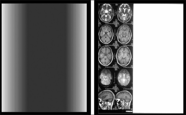
Left panel shows uneven low density compared to middle part of the image needing a print head profile calibration. Right panel shows image print limited to a vertical half due to dust at DICOM rastor engine
Summary and Conclusion
The functioning of a dry camera involves concurrent processes in areas of diverse sciences like computers, mechanics, thermal energy, optics, electricity and radiography. It is important to understand that all hard copy devices including dry imaging camera are not similar. When compared with the working knowledge and technical awareness of equipments in radiology, an understanding of hard copy devices including dry imaging camera is often superficial and neglected. To fill this void, this article outlines the key features of a dry camera and its impact on radiology workflow.
Acknowledgments
The authors wish to convey their appreciation to Agfa and Carestream technical support teams for their valuable inputs.
Footnotes
Source of Support: Nil,
Conflict of Interest: None declared.
References
- 1.Gahleitner A, Kreuzer S, Schick S, Nowotny R, Breitenseher M, Solar P, et al. Dry versus conventional laser imagers: Film properties and image quality. Radiology. 1999;210:871–5. doi: 10.1148/radiology.210.3.r99fe03871. [DOI] [PubMed] [Google Scholar]
- 2.Stewart M. Laser camera. A better view of life. From the beginning into the future, Kodak's health imaging division. [accessed on 2010 Nov 12]. Available from: http://www.e-radiography.net/cr/Laser%20Imager.pdf .
- 3.Neri LA. Keep an eye on dry. Med Imaging. 1996;2:47–51. [Google Scholar]
- 4.Nagda R. Medical hard copy devices: A review. Kodak (India) Radiograph. :47–67. [Google Scholar]
- 5.Borden M. Laser camera sales and service companies how fast are the wet and dry markets drying up? Or are the doomsayers all wet? DOTmed business news. [accessed on 2010 Nov 15]. Available from: http://www.dotmed.com/images/magazine/archive/072007.pdf .
- 6.Konica SRX 201A_Brochure. [accessed on 2010 Nov 15]. Available from: http://www.konicaminolta.com/content/download/10885/133180/SRX+201A_Brochure.pdf .
- 7.Kodak Dry View 8900 laser imager user guide. [accessed on 2010 Nov 15]. Available from: http://www.carestreamhealth.com/dv8900_userGuide_5E6155.pdf .
- 8.Agfa Axys. [accessed on 2010 Nov 15]. Available from: http://www.crzelarayan.com.ar/Axys/Preinstalacion_Axys.pdf .
- 9.New X-ray processors. [accessed on 2010 Nov 11]. Available from: http://www.amberusa.com/new_processors.asp .
- 10.Kodak Dry View 6800 laser imager. [accessed on 2010 Nov 15]. Available from: http://www.carestreamhealth.com/kodak-DryView-6800-laser-imager-system.html .
- 11.Laser. [accessed on 2010 Nov 19]. Available from: http://en.wikipedia.org/wiki/Laser .
- 12.Goulekas KE. Morgan Kaufmann Publishers; 2001. Visual effects in a digital world; p. 273. [Google Scholar]
- 13.Ball J, Price T, editors. 6th ed. Wiley-Blackwell; 1998. Recording the television image. Chesney's radiographic imaging; p. 334. [Google Scholar]
- 14.Ball J, Price T, editors. 6th ed. Wiley-Blackwell; 1998. Recording the television image. Chesney's radiographic imaging; p. 333. [Google Scholar]
- 15.Networking tutorial. [accessed on 2010 Nov 30]. Available from: http://www.comptechdoc.org/independent/networking/guide/netguide.pdf .
- 16.Kodak Dry View 5800 Laser Imager brochure. [accessed on 2010 Nov 28]. Available from: http://www.carestreamhealth.com/dv5800_brochure_M2-300.pdf .
- 17.DICOM 3.0 Conformance Statements. [accessed on 2010 Nov 21]. Available from: http://www.agfa.com/france/fr/he/service_assistance/interoperability/dicom/conformance_statements/index.jsp .
- 18.Kodak PACS Link Medical Image Manager Print Server (SCP) DICOM Conformance Statement. [accessed on 2010 Nov 23]. Available from: http://sysdoc.doors.ch/KODAK/3E5252 .
- 19.Clunie DA. DICOM Softcopy Presentation State Storage and Print Presentation LUT. [accessed on 2010 Nov 3]. Available from: http://www.dclunie.com/papers/spie_mi_nema_softcopy.pdf .
- 20.Max D. 2nd ed. Vol. 1. Bergsland D: On Word Press; 2002. Hardware needs. Chapter 4 Scanners Introduction to digital publishing; p. 105. [Google Scholar]
- 21.The world's only 100-megapixel dry medical imager. [accessed on 2010 Nov 11]. Available from: http://www.multiimager.com/pdf/DryView%208900a1.pdf .
- 22.Printers - DPI Printing Guide. [accessed on 2010 Dec 6]. Available from: http://www.castleink.com/_a-dpi-printing-guide.html .
- 23.Making sense of DPI, PPI, Megapixels and Resolution. [accessed on 2010 Dec 3]. Available from: http://www.atiz.com/resources/DPI-PPI-Megapixels-and-Resolution.pdf .
- 24.Kodak DryView 6800 laser imager brochure. [accessed on 2010 Nov 23]. Available as: dv6800_brochure_M2-294.pdf. Available from: http://www.carestreamhealth.com/dv6800_brochure_M2-294.pdf/
- 25.Krupinski EA, Williams MB, Andriole K, Strauss KJ, Applegate K, Wyatt M, et al. Digital radiography image quality: Image processing and display. J Am Coll Radiol. 2007;4:389–400. doi: 10.1016/j.jacr.2007.02.001. [DOI] [PubMed] [Google Scholar]
- 26.Agfa Drystar™ 5503 Datasheet. [accessed on 2010 Nov 27]. Available from: http://www.originindustries.com/Assets/Drystar%205503%20Data%20Sheetb.pdf .
- 27.Carestream DryView 5850 Laser Imager Brochure. [accessed on 2010 Dec 2]. Available from: http://www.carestreamhealth.com/dv5850_brochure_M2-411.pdf .
- 28.Cartridge recognition technology. [accessed on 2010 Nov 17]. Available from: http://www.carestreamhealth.com/kodak-DryView-laser-imaging-film.html .
- 29.Automatic Image Quality Control (AIQC) system. [accessed on 2010 Nov 11]. Available from: http://www.carestreamhealth.com/kodak-DryView-6800-laserimager-system.html .
- 30.Fuji Medical Dry Laser Imager Product Sheet. [accessed on 2010 Nov 19]. Available from: http://www.multiimager.com/pdf/DryPix7000.pdf .
- 31.Advanced Variable Response (A-VR) Spline Interpolation. [accessed on 2010 Nov 25]. Available from: http://www.fujifilm.com/products/medical/technologies/a_vr/
- 32.Kodak mammography Film. [accessed on 2010 Nov 11]. Available from: http://www.carestreamhealth.com/mammography.html .
- 33.Drystar DT2 mammography film. [accessed on 2010 Nov 11]. Available from: http://www.agfahealthcare.com/global/en/main/products_services/digital_hardcopy_imaging/dry_media/drystar_dt2_mammo.jsp .
- 34.Tsalafoutas IA, Tsapaki V, Koulentianos E, Triantopoulou C. Quality control of a laser camera with the SMPTE test pattern: Optical density variations with printing format and frame position. Br J Radiol. 2004;77:52–6. doi: 10.1259/bjr/62332261. [DOI] [PubMed] [Google Scholar]
- 35.Lu ZF, Nickoloff EL, Terilli T. Monthly monitoring program on DryView™ laser imager: One year experience on five Imation units. Med Phys. 1999;26:1817. doi: 10.1118/1.598686. [DOI] [PubMed] [Google Scholar]
- 36.Weberling R. Dry View laser imager: A new and economical image recording process. Aktuelle Radiol. 1996;6:355–60. [PubMed] [Google Scholar]
- 37.Gray JE, Anderson WF, Shaw CC, Shepard J, Zeremba LA, Lin PP. Multiformat video and laser cameras: History, design considerations, acceptance testing and quality control: Report of AAPM Diagnostic X-ray Imaging Committee Task Group No 1. Med Phys. 1993;20:427–38. doi: 10.1118/1.597036. [DOI] [PubMed] [Google Scholar]
- 38.Agfa Drystar 5300 manual. [accessed on 2010 Nov 13]. Available from: http://accessories.euro.gehealthcare.com/docs/pro/MID%20Printing%20Solutions%20and%20Video%20Systems/FILM%20IMAGERS/Agfa/Agfa_Drystar5300_manual_part2_eng.pdf .
- 39.Kodak DryView DVB Laser Imaging Film 4675. [accessed on 2010 Nov 17]. Available from: http://www.carestreamhealth.cn/dvDVB-DVC-DVBplusFilm_techInfo_ti5021.pdf .
- 40.X-ray Film. [accessed on 2010 Nov 5]. Available from: http://walshxray.com/xrayfilm.htm .
- 41.An Introduction to Photothermography. Sahyun MRV. [accessed on 2010 Nov 1]. Available from: http://www.imaging.org/ist/resources/tutorials/photothermography.cfm .
- 42.Bollen R. Method for providing hard copies of radiological images. [cited in 2010]. Available from: http://www.freepatentsonline.com/5549996.pdf .
- 43.Kodak Professional High-Speed Infrared Film. [accessed on 2010 Nov 24]. Available from: http://www.kodak.com/global/en/professional/support/techPubs/f13/f13.pdf .
- 44.Technical Information Sheets. [accessed on 2010 Nov 24]. Available from: http://www.carestreamhealth.com/ti.html .
- 45.AuntMinnie.com Buyer's Guide. [accessed on 2010 Nov 24]. Available from: http://www.auntminnie.com/index.asp?sec=vdpandsub=productsandpag=productsearchandtypeid=10239andfilterdefault=on .
- 46.Advance for Imaging and Oncology Administrators. [accessed on 2010 Nov 20]. Available from: http://imaging-radiation-oncology.advanceweb.com/sharedresources/advanceforioa/resources/DownloadableResources/AR_chartsmart_aug02.pdf .
- 47.Laser Imagers. [accessed on 2010 Nov 22]. Available from: http://www.jzimaging.com/laser%20imagers.htm .
- 48.CMX Medical Imaging. [accessed on 2010 Nov 23]. Available from: http://cmxmedicalimaging.com/content/pdf.php?nbr=91 .
- 49.Walker GE. [accessed on 2010 Nov 19]. Available from: http://gewalker.org/content/pdf.php?nbr=249 .