Abstract
Sacroiliac (SI) joint dislocations and sacral fractures of the pelvis can be stabilized by SI screws; however, screw insertion into a sacral isthmus region is risky for the adjacent neurovascular structures. Therefore, shape analyses of general SI screw corridors or safety zones are of great surgical interest; however, before such analyses can be conducted, a method for computing 3D models of general SI corridors from routine clinical computed tomography (CT) scans has to be developed. This work describes a method for determining general corridors in pelvic CT data for accurate screw placement into the first sacral body. The method is implemented with the computer language C++. The pelvic CT data are preprocessed before the presented algorithm computes a model of the 3D corridor volume. Additionally, the two most important parameters of the algorithm, the raster step and the virtual SI screw diameter, have been characterized. The result of the work is an algorithm for computing general SI screw corridors and its implementation. Additionally the influences of two important parameters, the raster step and the SI screw diameter, on corridor volume precision and computation time have been quantified for the test sample. We conclude that the method can be used in further corridor shape analyses with a large number of pelvic CT data sets for investigating general SI screw corridors and clinical consequences for the placements of the screws. Implementation of the presented software algorithm could also enhance performance of computer-assisted surgery in the near future.
Key words: 3D imaging, image analysis, bone and bones, computed tomography, image processing, software design, pelvis
Background
Sacroiliac (SI) screws are used to stabilize sacroiliac joint dislocations and sacral fractures. Screw insertion into the sacral isthmus region is technically difficult and potentially risky for the adjacent neurovascular structures.1–6 Malpositions of SI screws happens more often when variations in the morphology of the upper sacrum are not recognized.2,4,7,8 No knowledge about the exact 3-dimensional (3D) shape of the usable iliosacral bone stock for SI screw fixation exists yet. Therefore, additional shape analysis of the posterior pelvic ring is needed. Based on 3D CT reconstruction evaluations of the pelves in inlet, outlet, and lateral view are made to get more insight into common shape variations of all possible screw corridors. Furthermore, the determination of virtual corridor models produces references to evaluate the influence of the bony anatomy on the accurate insertion of transarticular screws. The relationship of the secure sacroiliac bone corridor within the pelvis and of externally recognizable pelvic anatomic points is described in.7
According to constraints imposed on screw positions, it is possible to generate two SI corridor models. It exists one for a transversal screw location and one as a result of the sum of all thinkable safe screw locations including oblique SI screw placement techniques.2 The first model is described in9 where the authors present two methods for computing transversal screw corridors. The present work describes a method for determining the corridor for all thinkable screw locations into the first sacral body by using a screw diameter of about 7.5 mm based on the idea and clinical input of the senior author, T. Mendel. For each corridor, the 3D shape and its volume are determined. Because of its computational complexity, the proposed method has been implemented in C++ in the form of a user-specific module within the Amira framework (Version 5.2.1, Visage Imaging, Inc., Pro Medicus Limited) and can be used for computing corridors of large numbers of pelvic CT data sets in an automatic way after some standard preprocessing of the CT data.
The computation of sacroiliac screw corridors provides the surgeon a better spatial understanding of the complex anatomy of the posterior pelvic ring. Especially, the individual sacral shape can extremely vary up to so-called “sacral dysplasia”. The 3D CT-based visualization of the usable secure bone stock allows a detailed analysis of limiting bone regions for the corridor. It represents an accurate research tool for further sacral shape analyses as well as the development of new implants for trauma surgery; however, the volume of the general corridor includes all thinkable positions of an SI screw in the first sacral segment without leaving the bone portion. Such a model even includes extreme screw positions which are potentially dangerous or are biomechanically not favorable for practical use.7 In addition, in the authors’ opinion, an implementation of the 3D corridor models in the surgical procedure is conceivable in the near future. Theoretically, the computational process of the corridors can be applied in all kinds of 3D data sets even in so-called 3D-image intensifiers which are just recently applied within trauma surgery. In summary, the general sacroiliac corridors can be suggested for research as well as for different manners of clinical applications such as described in10 where an experimental computer program for virtual operation of fractured pelvis and acetabulum based on real data of the fracture is presented.
Furthermore, automated computation of 3D bone corridors could enhance performance of computer-assisted surgery not only in pelvic applications. For example, a cadaveric study is planned where SI screws are inserted in the human pelves by computer-assisted imaging. For this purpose, the image data of the individually secure screw corridor will be implemented in the navigation software instead of the original pelvic CT data set. Then, postoperative CT scans can be analyzed with regard to the correct screw position within the virtual corridor.
Methods
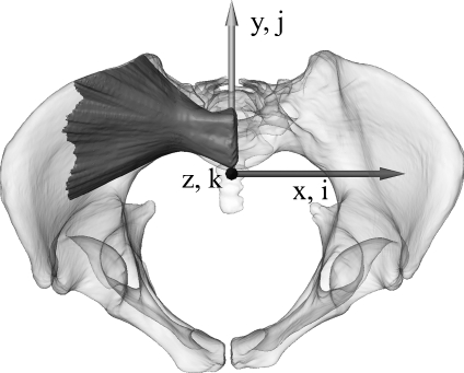
For the development of the algorithm, a routine multiple trauma masculine pelvic CT scan with a written patient’s consent was used. The scan was performed on a medical multislice CT scanner, Siemens SOMATOM Sensation 64 (Siemens AG, Erlangen, Germany), with an image resolution of 512 × 512 pixels, an overlapping slice thickness of 0.6 mm and the B45f kernel resulting in an image volume element (voxel) of 0.6 × 0.6 × 0.4 mm3. Before general corridors are determined, some preprocessing of a pelvic CT scan is performed such as described in.9,11 The bony structures of both os coxae and sacrum are semi-automatically segmented with the software Amira. Then, a triangulated surface is generated and transformed into a common coordinate system similar to the standard fluoroscopic inlet/outlet views which are used routinely in pelvic surgery. Such an alignment is important for an efficient and simplified algorithm development for subsequent screw corridor computation. The alignment transformation is derived from manually placed anatomical landmarks (promontorium, left and right spina iliaca anterior superior, and tuberculum pubicum). In this world coordinate system, the z axis is oriented to the central ray of the inlet view which is directed 40o to 60o caudal with respect to anterior–posterior (AP). The x axis points to the left (medial–lateral). The y axis is aligned with the central ray of the outlet view and is orthogonal to the zx plane. Figure 1 illustrates this well-defined coordinate system of the aligned pelvis together with a general bony corridor of the first sacral body. Voxels in the corresponding discrete image space are subsequently referenced by integer triples (i, j, k).
Fig 1.
The pelvic surface model with a general bony corridor of the first sacral body in the coordinate system (inlet view) used for corridor computation. World coordinates are given by triples (x, y, z) of real numbers and image coordinates by triples (i, j, k) of integer numbers.
In the next step, the transformed pelvic surface is converted into a volumetric representation resulting in a binary 3D image or label field with an isotropic voxel size of 0.5 × 0.5 × 0.5 mm3 referenced subsequently by the binary 3D image labelData (i, j, k) where the indices (i,j,k) address the corresponding location (voxel) of the space grid. A voxel value of 1 represents pelvic bone and a value of 0 represents empty space, i.e., the exterior of the pelvic bone or neurovascular structures. In addition, to mark the potential end points of the SI screws in the middle of the first sacral body S1 (parallel to the sagittal zy plane), we also labeled manually this cross section and called it startArea. In the following, this aligned and standardized label field (labelData) and this startArea are used for an automatic computation of the general corridor.
In short, the algorithm systematically evaluates all virtual screw positions starting from raster points of the start area in S1 and ending on raster points of the target area where real screws would enter into the pelvis. For the corridor determination, the algorithm considers only screw positions completely within bony material. The algorithm implemented in C++ uses the preprocessed volume data of the label field labelData (i, j, k) and writes the computed corridor into the label field labelCorridor (i,j,k) with the same bounding box and voxel size. The algorithm works on voxel level. It is composed of many nested loops such as shown in the following pseudo code where the lines 1, 2, 6, 8, and 11 represent procedures computing what is indicated by the corresponding text.
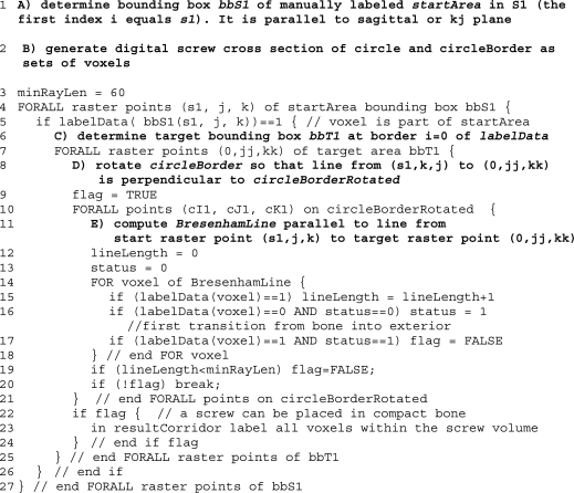
To initialize the algorithm first (line 1, A) the rectangular bounding box of the 2D start area is determined. Then (line 2, B) digitized circle areas and circle borders in the sagittal plane in the form of corresponding voxel sets are computed having a diameter d (7.5 and 8.5 mm) close to real SI screws (7.3 and 7.5 mm). Because of the discrete nature of the scans, only cross section diameters being an odd multiple of the scan resolution (0.5-mm voxel edge size) can be used. The target area is parallel to the start area and must be large enough to contain all potential intersections with screw lines in the general corridor of S1. We also define the constant minRayLen (line 3) which defines the minimal ray length of a general screw trajectory in compact bone. It is used to reject potential screw trajectories entering into the spinal canal or not leaving the pelvis laterally. Then we define the search raster in the start and target areas for the general corridor determination, i.e., for each raster point in the start area to each raster point in the target area the screw corridor of thickness d is examined to find out whether it is completely within the compact bone without touching neurovascular structures. Typically, this raster is uniform in both areas and is given by every third or fourth voxel in z and y directions. The best result would be obtained by using all voxels of the start and target areas as raster points, but as the computational complexity of the algorithm in this fourfold nested loop grows exponentially, a compromise has to be found to compute the corridors in a reasonable time.
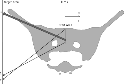
When in line 5 the raster point of bbS1 is within the manually segmented start area, the search for possible screw corridors to all other target points is started. First, however (line 6, C), the lower limit of the target area bbT1 has to be determined. It is not constant but varies linearly with the height or K-index of the start point. This is necessary because otherwise, starting at low points, it could be possible that corridors that penetrate S2 could be found passing between the first and second spinal canal such as illustrated by arrow 1 in Figure 2. For higher start points, however, this end point or even lower ones could be regularly hit such as illustrated by the arrow 2 in Figure 2.
Fig 2.
Outlet view of a cross section of a pelvic label field with start and target areas (represented as lines because they are orthogonal to view plane) of S1 corridors as well as three critical screw placements represented by the arrows 1 to 3.
In line 7, the testing of all end raster points starts in order to determine whether they could be potential end points of a screw corridor starting from the current start raster point. First (line 8, D) the digital circle is rotated so that it is perpendicular to the line from the current start point to the current end point. In order to decide whether the corresponding disk-like cross-sectional area of the screw corridor is completely within the compact bone, it is sufficient to consider only its border voxels. In line 9, the state variable flag is initialized. It is needed for detecting valid screw corridors. The loop starting in line 10 examines now all border voxels of the rotated disk-like cross-sectional area of the screw. Initially, we compute the sequence of all voxels along a digital Bresenham line from the start to the corresponding end point (line 11, E). After the initialization of the line length variable and the status variable’s status, each voxel along the current Bresenham line is examined (lines 14 to 18). If the voxel is within the compact bone, the lineLength variable is incremented (line 15). If the voxel value does not correspond to the compact bone and if the status variable is 0 then the status variable is incremented (line 16). This means that the Bresenham line has left the compact bone for the first time. If the status variable has the value 1 and if the voxel value corresponds to the compact bone (line 17), then the variable flag is set to FALSE because the Bresenham line has entered for the second time into the compact bone which is not allowed for a screw volume voxel. If the examination of the Bresenham line has been completed (line 18), the line length within the compact bone is compared to the minimal ray length (line 19). If it is smaller than the predefined value, the flag variable is also set to FALSE because in this case, this Bresenham line cannot be part of a valid screw volume borderline. If in line 20 the flag variable is FALSE, then the examination of this screw volume can be terminated, otherwise, it has to be continued until all Bresenham lines through the border voxels of the rotated disk-like cross-sectional areas of the screw have been checked. If all lines are within the compact bone, then we have a valid screw volume around the current start raster point to the current target raster point. Subsequently, this screw volume can be labeled in the result label field resultCorridor (lines 22 to 24). These steps are executed for all start raster points and result finally in a general screw corridor such as illustrated in Figure 1.
Results
The main result of this work is an algorithm for automatic computation of general SI screw corridors for preprocessed and aligned 3D models of pelves derived from CT scans. In addition, the algorithm has been characterized by varying two important parameters, the screw diameter and the raster steps of the screw start and end areas for the corridor computation.
According to Table 1, the computing time of the general corridors varies strongly with the raster step of the target and start areas. It takes about one and a half minute for 3.5-mm raster steps and about 35 min for 1.5-mm raster steps.
Table 1.
Influence of screw diameter and raster step of start and target areas on computing time and volume of a general S1 corridor of a pelvis
| Diameter of disk-like screw cross section (mm) | Raster step (mm) | Computing time (s) | Volume (mm3) |
|---|---|---|---|
| 7.5 | 1.5 | 2,110 | 164,107 |
| 2 | 663 | 161,867 | |
| 2.5 | 277 | 157,135 | |
| 3 | 140 | 152,796 | |
| 3.5 | 87 | 150,642 | |
| 8.5 | 1.5 | 2,275 | 157,494 |
| 2 | 734 | 153,975 | |
| 2.5 | 306 | 149,971 | |
| 3 | 161 | 148,896 | |
| 3.5 | 90 | 144,440 |
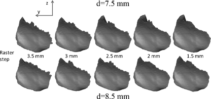
The isolated computed corridors with the parameter variations are shown in Figures 3 and 4. Figure 3 shows the lateral view of the corridor surfaces where the screws penetrate the os coxae. It can be noted that the upper borders, especially for the large raster steps, are not very smooth and reflect roughly the raster steps and the screw diameters.
Fig 3.
Lateral view from inside of the pelvis on the corridor start area. The raster step (left 1.5 mm to right 3.5 mm) and the screw diameter (above 7.5 mm–below 8.5 mm) have been varied when computing the corridor volume.
Fig 4.
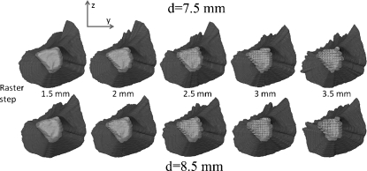
Lateral view from inside of the pelvis on the corridor start area. The raster step (left 3.5 mm to right 1.5 mm) and the screw diameter (above 7.5 mm–below 8.5 mm) have been varied when computing the corridor volume.
Figure 4 shows again a lateral view of the corridors, but now from the opposite side, the inside of the pelvis with the start area. Again, we can see the visual effects of the raster step and screw diameter variations.
Discussion
The computation of the general screw corridor with the proposed algorithm is time consuming as each raster point of the 2D start area is linked with every 2D raster point of the 2D target area in order to decide whether it could correspond to a valid screw position. Therefore, it is proportional to nz,startnz,startnz,targetny,target, the numbers of raster points of the start and target areas along the corresponding axes. Doubling the raster point resolution along each axis increases theoretically the complexity by the factor 24 = 16, for example.
In contrast, the influence of the screw diameter on the computing time is only small. The computation of the corridors with the larger 8.5-mm screw diameter lasts only 3 s longer for the 3.5-mm raster step and about 3 min longer for the 1.5-mm raster step. It is evident that the corridor volume decreases slightly with increasing raster steps and screw diameter.
However, the observed effects on the corridor volume are not very important within the observed parameter variations. The smallest volume is only 12% smaller than the largest one. It is also evident that the most accurate result is obtained with the smallest raster step of 1.5 mm. In this case, the screw diameter of 8.5 mm produces a 4% smaller corridor volume than the 7.5-mm thick screw.
As already indicated in the results section and according to Figure 3, the upper border of the corridor volume, especially for the large raster steps, is not very smooth and reflects roughly the raster steps and the screw diameters. This effect is evident because in this region, the angle between the screw and the pelvic surface is relatively small (see also Fig. 2, ray 3). Therefore, small angle variations of the screw placement produce much larger surface intersection variations than in regions where the screw hits perpendicularly the pelvic surface.
To estimate the size of potential border effects, such as the partial volume effect for example, due to the scan resolution of about 0.5-mm voxel edge size we compared also the corridor volume with its shrunk version obtained by eliminating its one-voxel-thick outer shell. The volume difference is then 6.3% being in the same range produced by the variations of the screw diameter and the raster step of the algorithm. Consequently, we conclude that higher accuracy cannot be obtained without increasing the scan resolution.
Conclusion
We have presented a method for computing general SI screw corridors from pelvic CT data. With regard to further studies analyzing a large number of SI screw corridors, the most appropriate result is obtained with the lowest tested raster step of three voxels or 1.5 mm in 35-min computation time for one corridor. It is a compromise between precision and computation time. Smaller raster steps would even yield slightly more precise corridor volumes, but the computation time would increase considerably because of the exponential growth of the computational complexity. Generally, a longer running algorithm with a more precise corridor might be better than a shorter running one, but it has to be computable in a reasonable time.
We think that the method is suitable for the evaluation of large sets of pelvic CT data within future studies, investigating in detail, the shape variations and their consequences on the placement of SI screws. It is able to reveal the influence of anatomical shape variability particularly sacral dysplasia occurring in up to 35% of the human population.4,12 Moreover, the algorithm can easily be adjusted to be used with differently placed start areas in the sacral bodies S1, S2, or S3. It has also to be mentioned that the penetration depth of the screw into the sacrum significantly influences the shape and size of the general corridor.
Further general corridor analyses of more pelvic CT data sets, as planned for future work, could improve surgical guidelines for safe screw insertions.
Acknowledgements
The authors would like to thank the AO Foundation for supporting this project. Furthermore, we thank Lukas Kamer for supportive comments and insightful debates. Thanks also to Thomas Heldstab for his contributions in preparing and evaluating the data.
Contributor Information
Hansrudi Noser, Phone: +41-81-4142589, FAX: +41-81-4142285, Email: hansrudi.noser@aofoundation.org.
Florian Radetzki, Email: florian.radetzki@gmx.de.
Karsten Stock, Email: karsten.stock@medizin.uni-halle.de.
Thomas Mendel, Email: thomasmendel@hotmail.com.
References
- 1.Cecil ML, Rollins JR, Jr, Ebraheim NA, et al. Projection of the S2 pedicle onto the posterolateral surface of the ilium—A technique for lag screw fixation of sacral fractures or sacroiliac joint dislocations. Spine. 1996;21:875–878. doi: 10.1097/00007632-199604010-00022. [DOI] [PubMed] [Google Scholar]
- 2.Day CS, Prayson MJ, Shuler TE, et al. Transsacral versus modified pelvic landmarks for percutaneous iliosacral screw placement—A computed tomographic analysis and cadaveric study. Am J Orthop. 2000;29:16–21. doi: 10.1007/PL00003675. [DOI] [PubMed] [Google Scholar]
- 3.Ebraheim NA, Lin D, Xu R, et al. Evaluation of the upper sacrum by three-dimensional computed tomography. Am J Orthop. 1999;28(10):578–582. [PubMed] [Google Scholar]
- 4.Routt ML, Jr, Simonian PT, Agnew SG, et al. Radiographic recognition of the sacral alar slope for optimal placement of iliosacral screws: A cadaveric and clinical study. J Orthop Trauma. 1996;10:171–177. doi: 10.1097/00005131-199610000-00015. [DOI] [PubMed] [Google Scholar]
- 5.Xu R, Ebraheim NA, Yeasting RA, et al. Morphometric evaluation of the first sacral vertebra and the projection of its pedicle on the posterior aspect of the sacrum. Spine. 1995;20:936–940. doi: 10.1097/00007632-199504150-00010. [DOI] [PubMed] [Google Scholar]
- 6.Mendel T, Kuhn P, Wohlrab D, Brehme K. Minimally invasive fixation of a sacral bilateral fracture with lumbopelvic dissociation. Unfallchirurg. 2009;112(6):590–595. doi: 10.1007/s00113-008-1563-0. [DOI] [PubMed] [Google Scholar]
- 7.Mendel T, Appelt K, Kuhn P, et al. Bony sacroiliac corridor—A virtual volume model for the accurate insertion of transarticular screws. Unfallchirurg. 2008;111:19–26. doi: 10.1007/s00113-007-1386-4. [DOI] [PubMed] [Google Scholar]
- 8.Routt ML, Jr, Kregor PJ, Simonian PT, et al. Early results of percutaneous iliosacral screws placed with the patient in the supine position. J Orthop Trauma. 1995;9:207–214. doi: 10.1097/00005131-199506000-00005. [DOI] [PubMed] [Google Scholar]
- 9.Noser H, Radetzki F, Stock K, Mendel T. Methods for computing transversal iliosacral screw corridors in CT-data of the pelvis. Int J CARS. 2010;5(Suppl 1):S8–S10. [Google Scholar]
- 10.Cimerman M, Kristan A. Preoperative planning in pelvic and acetabular surgery—The value of advanced computerised planning modules. Injury. 2007;38(4):442–9. doi: 10.1016/j.injury.2007.01.033. [DOI] [PubMed] [Google Scholar]
- 11.Radetzki F, Noser H, Stock K, Mendel T: Analysis of the posterior pelvic ring obtaining radiological data for safe iliosacral screw insertion. The XIth Congress of the International Society of bone Morphometry (ISBM), Ferry Porsche Congress Center. Zell am See, Austria, 2009, 28.5–30.5
- 12.Carlson DA, Scheid DK, Maar DC, Baele JR, Kaehr DM. Safe placement of S1 and S2 iliosacral screws: The “vestibule” concept. J Orthop Trauma. 2000;14(4):264–9. doi: 10.1097/00005131-200005000-00007. [DOI] [PubMed] [Google Scholar]


