Abstract
This software tool locates and computes the intensity of radiation skin dose resulting from fluoroscopically guided interventional procedures. It is comprised of multiple modules. Using standardized body specific geometric values, a software module defines a set of male and female patients arbitarily positioned on a fluoroscopy table. Simulated X-ray angiographic (XA) equipment includes XRII and digital detectors with or without bi-plane configurations and left and right facing tables. Skin dose estimates are localized by computing the exposure to each 0.01 × 0.01 m2 on the surface of a patient irradiated by the X-ray beam. Digital Imaging and Communications in Medicine (DICOM) Structured Report Dose data sent to a modular dosimetry database automatically extracts the 11 XA tags necessary for peak skin dose computation. Skin dose calculation software uses these tags (gantry angles, air kerma at the patient entrance reference point, etc.) and applies appropriate corrections of exposure and beam location based on each irradiation event (fluoroscopy and acquistions). A physicist screen records the initial validation of the accuracy, patient and equipment geometry, DICOM compliance, exposure output calibration, backscatter factor, and table and pad attenuation once per system. A technologist screen specifies patient positioning, patient height and weight, and physician user. Peak skin dose is computed and localized; additionally, fluoroscopy duration and kerma area product values are electronically recorded and sent to the XA database. This approach fully addresses current limitations in meeting accreditation criteria, eliminates the need for paper logs at a XA console, and provides a method where automated ALARA montoring is possible including email and pager alerts.
Key words: Peak skin dose, sentinal event, DICOM structured report dose, patient entrance reference point, fluoroscopy, interventional radiology, Joint Commission (JC), radiation dose, Digital Imaging and Communications in Medicine (DICOM)
Background
Numerous episodes of severe skin damage and harm to patients have occurred due to elevated X-ray exposures during fluoroscopically guided interventional procedures.1,2 Patient skin doses from the use of X-rays in interventional X-ray angiography (XA) procedures continue to exceed the threshold doses for deterministic effects such as erythema and epilation.3,4 Since 1994, the FDA and more recently the Joint Commission5 have specified that skin exposures from fluoroscopy be routinely monitored as a quality assurance (QA) metric. High skin doses that cause erythema must be identified and the patient must be informed. Appropriate medical care must be provided should this occur. An X-ray exposure to a localized region of the skin (i.e., peak skin dose) that exceeds 15 Gy is now included as a sentinel event, and it is mandated to be reported to the Joint Commission.6
Nonetheless, peak skin dose itself is rarely, if ever, monitored because of the current inability to compute and localize the skin exposure to the patient. Today, monitoring is commonly accomplished via a paper or electronic recording at the end of examination of the cumulative air kerma (Gy) to the patient entrance reference point (PERP),7 kerma area product (KAP or Gym2), and/or elapsed fluoroscopic time (minutes). The result of choosing a unit such as KAP to predict an episode of erythema or epilation leads to assumptions which can easily be overly conservative and are known to be inaccurate estimates of peak skin dose.8,9 To address these limitations and to enhance the routine QA monitoring of XA peak skin dose exposures, a set of modular simulation tools and a database were developed. This simulation tool works by capturing required information from Digital Imaging and Communications in Medicine (DICOM) tags including data from DICOM Structured Report Dose. With other system-specific parameters, this tool automatically maps peak skin dose on the phantom patient.
Methods
The complete system is comprised of simulated male and female patients, simulated and configurable C-arms, a robust database that automatically accepts DICOM tags including DICOM Structured Report Dose tags (11 are required) ,and the four additional system parameters that are necessary for peak dose estimation (these are entered via a technologist and physicist screen). One additional tag is read from DICOM header file to determine whether collimator shape is round or rectangle. Two-way exchange of data from all XA systems with the database are needed to complete the computation, recording, and archiving of patient dose and location.
The approach taken to estimate skin dose is to first locate and properly position the virtual patient on the table. With the center top of the patients head as the origin, the air kerma to each 0.01 × 0.01 m2 region at the surface of the patient likely to be struck by the X-ray beam is computed. Knowledge of the shape of the surface and the distance from each region to the origin permits trigometric determination of the 0.01 × 0.01 m2 regions exact location in space. Knowledge of table positions and gantry angulations (validated data from DICOM and system parameters) specifies the field size on the patient surface. Knowledge of each 0.01 × 0.01 m2 of the patient surface relative to PERP permits appropriate corrections for inverse square law. Other required corrections also apply backscatter for determination of skin dose (since both the kVp and the field size on the patient surface are determined). Corrections also can be applied for table and pad attenuation and calibration factors for the exposure (corrections to the vendors specified value at PERP).
Computed peak skin dose (Gy) and location recorded in the database after each exam can automatically initiate email or pager alerts based upon predetermined threshold values for peak skin dose (Action Levels).
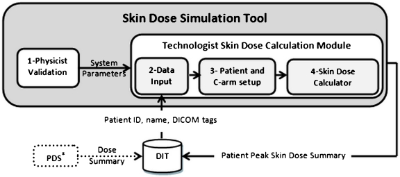
A schematic of data flow is summarized as shown in Figure 1.
Fig 1.
Skin dose tool. (1) A physicist validates and enters system parameters once per system. (2) The technologist enters modality, station ID, and date to retrieve DICOM data from DIT after each patient exam is finished. (3) Technologist checks patient position on the table and C-arm setup at the end of the exam. (4) Clicking on Skin Dose Calculator performs the calculation and archives a patient skin dose record to DIT. PDS paper printable dose summary—available with some XA units. These data can be electronically captured if desired.
Male and Female Virtual Patients
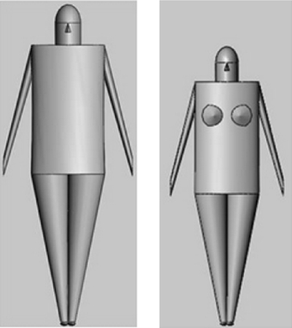
SolidWorks (2009 x64 Edition SP5.0 Concord, MA, USA) simulation software was used to construct standardized male and female phantoms using biometric values using NASA, Man-Systems Integration Standards.10 While multiple phantom options exist,11,12 mathematical models enable the straightforward location of any point on the surface of the model because the geometry, shape, and dimensions are known. This was considered advantageous in this application. The height of the standard adult male phantom is approximately 1.86 m and the weight is ~90 kg, while the height for adult female phantom is ~1.67 m and weight is 72 kg. While the arms (Figure 2) are included for completeness, they are not used in the calculation of skin dose. In clinical practice, the arms are carefully avoided during any XA procedure and would be extended away from the region of X-ray interest. The female phantom breast is included in this model, and skin dose to the breast is computed. Because these three-dimensional mathematical male and female models are constructed from defined elliptical cylinders and cones, coordinates of the surface of the body are derived using geometric computations. Upon completion of each procedure, the technologist enters gender, height, and weight estimates, along with patient orientation on the table (supine/prone, feet or head first, and left or right lateral), and a corresponding phantom is automatically loaded. Thus, calculation of all skin dose values are performed after the exam is finished.
Fig 2.
Standard male and standard female phantoms. Sizes are based on NASA, Man-Systems Integration Standards.10
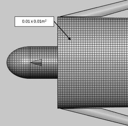
The surface of the phantom is reduced to regions of 0.01 × 0.01 m2 (Figure 3). Knowing the geometry of the phantom (surface) relative to the placement of the patient on the table permits the calculated (x, y, f (x, y)) location for each point of the skin (center of the 0.01 × 0.01 m2 square), where f(x, y) maps x and y coordinate of each point to corresponding z coordinate based on mathematical geometry used in phantom construction.
Fig 3.
Standard male phantom. The surface area of the model (except for arms) is localized to each 0.01 × 0.01 m2. These regions are referenced to the origin (top center of the head).
Virtual Equipment Configuration and Geometry
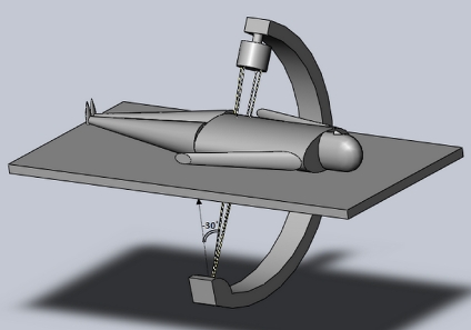
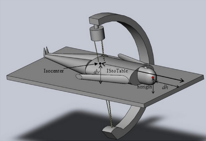
SolidWorks simulation software was used to depict conventionally available angiographic C-arm equipment including XRII (X-ray image intensification) and solid state (flat panel digital) X-ray receptors. The patient can be positioned on the table with the patient head to the right (Figure 4) as with head first, or feet to the right (feet first). The patient can also be positioned as prone, supine, or left or right side. Software provides visual confirmation of each episode positioning for technologist and physicist validation. Figure 4 is a typical single C-arm digital detector configuration with the patient positioned head first and supine. The direction of +x axis is the longitude (moving cranial–caudal), while the direction of +y axis is to the patient left. The +z axis directs to the front of the patient.13 The software simulation image display actually rotates the displayed gantry following keyboard data entry (to visualize in comparison with the actual gantry). This was found particularly useful as an aid in validating DICOM tag geometry values during initial physicist acceptance when the patient can be switched from prone to supine as an example.
Fig 4.
Displayed gantry angle of −30° for an image intensifier C-arm. Male patient is supine, centered in y, and head first.
Patient—Table Geometry
Primary and Secondary Gantry Angles
The primary gantry angle (Figure 5) is when a patient is left anterior oblique–right anterior oblique (LAO-RAO) (y–z plane). At 0°, the X-ray tube is beneath the patient and is pointed vertically upwards. A positive primary angle corresponds to an X-ray beam that enters the patient from the patient’s right posterior and exits to the patients left anterior. The secondary angle is the cranial–caudal (x–z plane). At 0° for secondary angulations, the X-ray tube is beneath the patient; a positive secondary angle corresponds with the tube arcing to the patient toes and detector moving toward the patient head. Movement of the C-arm or table horizontally or vertically is discussed below. Note: Importantly, the technologist enters the patient positioning (i.e., supine or prone) at the XA operator console, which alters (as validated) the DICOM tag values recorded in the database at the end of the exam for primary and secondary angles. These values are considered patient centric when matching with position automatically occurs.
Fig 5.
Simulated fluoroscopic X-ray equipment configurations and system coordination.
Definition of System Origin and PERP
Regardless of recorded values of table movement (longitudinal, lateral, and up–down), we assume that the origin be always set at the center of the top of the head of the phantom (Figure 5), and the coordinate system for all 0.01 × 0.01 m2 regions is referenced to this point location. The PERP is a point in space located 0.15 m toward the X-ray source from the isocenter of rotation of the C-arm.7 The program calculates the skin exposure that occurs to each 0.01 × 0.01 m2 from the reported exposure to the PERP using knowledge of distances.
DICOM Tags: Type I and II Equipment
XA equipment for localized skin dose computations are classified into two groups: type I and type II.
Type I equipment are provided with DICOM Structured Report Dose (DSR). Each footswitch activation provides data for both acquisitions (digital spots, cine, and DSA) and fluoroscopy. DSR provides 11 of the 16 necessary data to calculate exposure to each 0.01 × 0.01 m2 areas. Four additional input parameters are needed (see Table 1, type I column). An XA technologist must enter one distance measurement once per procedure, and three entries are needed to be entered by the physicist once per system during validation to calculate localized skin dose.
Table 1.
Input data for type I and type II equipment
| Input data | Description | Type I | Type II |
|---|---|---|---|
| α1 | Primary end angle | In DSR acquisition and fluoroscopy | In DICOM Acquisition. But no fluoroscopy |
| α2 | Secondary end angle | In DSR acquisition and fluoroscopy | In DICOM acquisition. But no fluoroscopy |
| KAP acquisition | Kerma area product per event | In DSR acquisition KAP/acquisition dose = area at PERP | PDS KAP/acquisition dose = area at PERP |
| KAP fluoroscopy | Kerma area product per event | In DSR fluoro KAP/fluoro dose = area at PERP | Summary is available in PDS but not used |
| Acquisition dose | Air kerma at PERP (Gy) | In DSR, per event | In PDS, per event |
| Fluoroscopy dose | Air kerma at PERP (Gy) | In DSR, per event | In PDS (not by event) proportionally added to acquisition dose |
| Radius | Dist Source to the C-arm Isocenter | In DSR | Physicist screen data |
| dv | Vert. dist isocenter to the table plane | In DSR | DICOM header file |
| TLatInc | Table lateral increment | In DSR | Default value of 0 |
| TLongInc | Table longitudinal increment | In DSR | Default value of 0 |
| Patient orientation | Orientation of the patient | In DSR | Normally provided as tag |
| dh | Horiz dist from patient origin to the head of table | Technologist screen data | Technologist screen data |
| HCH | Horiz dist from current C-arm to home position | Physicist screen data | Physicist screen data |
| HTC | Horiz dist table home to C-arm home position | Physicist screen data | Physicist screen data |
| TL | Table length | Physicist screen data | Physicist screen data |
| Collimator shape | Round shape or rectangular | DICOM header file | DICOM header file |
PDS printable dose summary
Type II XA equipment are not provided with DSR but do provide a number of useful DICOM tags, which permit estimation of peak skin dose. Type II equipment operator consoles may be provided with a printable dose summary (PDS) designed for paper printing. It is possible to print these data to a virtual printer and electronically capture dose descriptive information to the DICOM Index Tracker (DIT) database. DICOM tag and PDS information are footswitch specific for acquisition, and therefore, peak skin dose can be directly calculated for type II equipment, except for the fluoroscopy component. Fluoroscopy data in type II equipment are only provided in summary form. In our implementation, the total (reported) fluoroscopy exposure is distributed to peak skin dose locations in an amount proportional to the dose received from acquisitions. The localized skin dose and locations with acquisition is first calculated, and the total skin dose is then scaled prorated to these locations. With type II equipment, default values are used for lateral and longitudinal table position. As with type I equipment, an entry of a distance measure by the technologist and three one-time specifications by the physicist are required.
Physicist System Validation
Comprehensive reviews of XA equipment geometry, radiation dose measurement, and DICOM tag inspection are necessary to implement this approach for localizing peak skin dose. As an aid to these tasks, a physicist screen (Figure 6) provides some assistance in validating the system. Screen data fields are available for attenuation corrections for table and pad, separate calibration corrections for fluoroscopy and acquisitions KAP at PERP, and desired back scatter factor use. Choice of preferred default values may be selected. DICOM tag values must be reviewed and validated, including gantry angulations, table positions, C-arm movement if possible, and correctness of a patient centric use of distances and equipment type, including bi-plane and detector type. The equipment chosen is displayed, and by clicking on Display, the positional information on the C-arm image is updated so that the physical gantry, virtual C-arm, and tag data are co-registered. Also specified (keystroke entered) are the list of physician authorized users and ALARA values.
Fig 6.
Physicist validation interface once per system. Copyrighted and used with permission from Mayo Foundation for Medical Education and Research. All rights reserved.
Computation of Peak Skin Dose
A “point” within a 0.01 × 0.01 m2 area is assigned the computed value. Each representing point on the discretized surface has the coordinate (m ± 0.5, n ± 0.5, f(m ± 0.5, n ± 0.5)) assuming m and n as integers. To expedite the computation, the irradiated regions (projected X-ray field on the surface of the patient) are initially determined using the positioning of the C-arm. Other patient geometries are discussed below.
HCH is the horizontal distance from the C-arm current (radiation event) position to C-arm home position (home positions for both table and C-arm are defined by the system (0, 0)). HTC is the horizontal distance from table home position to C-arm home position and is specified by the physicist once during validation. The notations in Table 2 are used in the calculation of specified locations.
Table 2.
List of required distances for calculating coordinates of isocenter, source, and PERP
| Notation | Definition | Value |
|---|---|---|
| Horigin | Vertical distance from origin (patient head) to the table top depicted in Figure 7 | Male, 0.10 m |
| Female, 0.09425 m | ||
| IStoTable | Horizontal distance from isocenter toward patient head to the edge of table—head first position | HCH—HTC − TLongInc + TL/2 |
| Distance | Distance from isocenter to top head of the patient | |IStoTable − dh| |
The following notation is used to represent indices for calculation.
- IS
Index identifying isocenter
- RF
Index identifying PERP
- Spot
Index identifying X-ray source
- c1, c2, c3, c4
Corners of area at patient entrance reference point for rectangular cone
The coordinates of isocenter (xIs, yIs, zIs) can be computed as follows:
 |
1 |
 |
2 |
 |
3 |
A general formulation corresponding to the coordinates of X-ray source (xspot, yspot, zspot) and PERP (xRF, yRF, zRF) is:
 |
4 |
 |
5 |
 |
6 |
 |
7 |
 |
8 |
 |
9 |
Note: In Eqs. 7, 8, and 9, the length 0.15 m is the distance from PERP to the X-ray source.
Fig 7.
Depiction of certain needed distances (listed in Table 2) based on our proposed coordinate system.
Calculation of Air Kerma to Each Region of Skin (0.01 × 0.01 m2)
The method of how to isolate the irradiated points of the patient surface struck by the X-ray beam is discussed in the Appendix. For each point of (x, y, z) of the radiated area, we calculate the distance from the X-ray source to each 0.01 × 0.01 m2 point of the applicable area using Eq. 26 of the Appendix as follows,
 |
10 |
Since PERP is defined as 0.15 m from isocenter toward the X-ray source.
 |
11 |
Here, Kskin and KPERP are the air kerma at the patient skin and PERP, respectively.
Each of the irradiated points at the surface of the virtual patient for each run is calculated, and inverse square law corrections are made for individually differing distances to the surface of the patient.
Tables 3 and 4 list the needed corrections when the patient is optionally positioned on the table.
Table 3.
Vertical distance from origin (top center of patient head) to the table top for standard phantom
| Parameter | Notation | Position of the body | Standard male body | Standard female body |
|---|---|---|---|---|
| Vertical distance from origin (patient head) to the table top | Horigin | Prone | 0.10 m | 0.09425 m |
| Left lateral or right lateral | 0.20 m | 0.1885 m |
Table 4.
Adjustment required for primary and secondary angles for different patient positions
| Patient position | Primary angle | Secondary angle |
|---|---|---|
| Supine—head first | α1 | α2 |
| Supine—feet first | −α1 | -α2 |
| Prone—head first | π + α1 | α2 |
| Prone—feet first | π − α1 | −α2 |
| Left lateral—head first | π/2 + α1 | α2 |
| Left lateral—feet first | π/2 + α1 | −α2 |
| Right lateral—head first | −π/2 − α1 | α2 |
| Right lateral—feet first | −π/2 − α1 | −α2 |
An adjustment must be applied when patient positioning is feet first; then, distance in Eqs. 1, 4, and 7 will be represented as Eq. 12.
 |
12 |
These adjustments would be applied to the above equations as applicable.
Back Scatter Factor
Table 5 is a partial listing of back scatter factors that are used, a required and significant correction to the calculated air kerma.14 A back scatter factor for a tube voltage of 80 kV, filter 3.0, HVL 3.04, and field size 0.2 × 0.2 m2, is 1.40, which is the default value. Calculated air kerma (Eq. 11) values are corrected using back scatter factor, thereby converting air kerma to skin dose.
 |
13 |
Table 5.
Partial table of back scatter factors reproduced from ICRU14 for body tissue
| Tube voltage (kV) | Filter | HVL (mm AI) | Field size | |||
|---|---|---|---|---|---|---|
| ICRU TISSUE | ||||||
| 0.1× 0.1 m2 | 0.2 × 0.2 m2 | 0.25 × 0.25 m2 | ||||
| 80 | 2.5 | 2.78 | 1.33 | 1.39 | 1.39 | |
| 80 | 3.0 | 3.04 | 1.34 | 1.40 | 1.41 | |
| 80 | 3.0 | +0.1 mm Cu | 4.55 | 1.40 | 1.50 | 1.51 |
| 90 | 2.5 | 3.17 | 1.34 | 1.41 | 1.42 | |
| 90 | 3.0 | 3.45 | 1.36 | 1.43 | 1.44 | |
| 90 | 3.0 | +0.1 mm Cu | 5.12 | 1.41 | 1.51 | 1.53 |
Upon summing the skin dose received by each 0.01 × 0.01 m2 regions of skin (when overlap occurs with each fluoroscopic and acquisition event of one exam), the skin dose at each 0.01 × 0.01 m2 region is computed.
Results
Technologist Screen
Figure 8 presents the screen used by the technologist for a procedure. Selecting the gender, height, and weight of the patient establishes the match for the phantom. Physician operators are chosen from a predetermined listing of users. Patient positioning is noted, including the distance from the top of the patient’s head to the end of the table. The equipment selection confirms the imaging lab being used and is used to retrieve the patient-specific acquisition and fluoroscopy information for calculation at the end of the procedure. Clicking on “Calculate Skin Dose” results in a patient-specific dose screen (Figure 9).
Fig 8.
Technologist screen validates the patient phantom size and positioning. It automatically connects to the XA database for calculating and recording patient dose once per procedure. Copyrighted and used with permission from Mayo Foundation for Medical Education and Research. All rights reserved.
Fig 9.
Patient summary dose report. Copyrighted and used with permission from Mayo Foundation for Medical Education and Research. All rights reserved.
Patient Dose Summary Screen
This tool localizes the peak skin dose only upon completion of a procedure. A completed XA exam is sent to PACs, and a copy of all data are received by the XA database module in DIT.15 This database captures DICOM tags and maintains longitudinal record of patient specific dose indices for all diagnostic and procedural uses of ionizing radiation. It is comprised of a knowledge base of known devices (i.e., modalities), the standard and proprietary DICOM tags, a patient episode dose tracking database, dosimetry analyzer tools, a configurable web reporter, and an alert and auto-messaging reporting mechanism. The XA Skin Dose tool connects to this database and fetches the required data. An Excel macro automatically retreives to the imaging suite all available XA tags. With the four required system parameters, the program performs the calculations and localizes the peak skin dose. A Patient Summary screen displays the results and other data that may be collected by the XA techologist for QA monitoring. Action Levels of localized dose are color-coded on the patient phantom. Individual 0.01 × 0.01 m2 computed values describing localized dose are sent to DIT, which permits the alerting function of DIT to email or page the physician user and the QA staff when ALARA criteria are met (Figure 9).
Automatic email, cell phone, and internal pager alerts from the DIT are in use.
Discussion
A clear need exists to more fully communicate to the patient, medical staff, and the hospital QA review committee the actual or likelihood of a deterministic radiation effect following an XA procedure. Minutes of fluoroscopy are highly inaccurate, while KAP and cumulative exposure are quite variable in estimating peak skin dose.16 The impediments to recording the localized skin dose value are founded in the need for having a reasonable representation of the patient’s specific size and shape and by having representative patient positioning in actual XA equipment use. We attempt to address this problem by using virtual patients coupled with visualized representation of the equipment. With DICOM Structured Report Dose tag data and four added data entries, a reasonable estimation of peak skin dose appears attainable. Future effort is needed to fully document the comparison of computed and measured values of localized dose. Although we have performed several blinded comparisons of measured and computed dose values having reasonable agreement, we intend to fully report on the accuracy of these computations in a future publication.
An important component of this implementation is the connection to a database that is robust with XA equipment and DICOM tag knowledge and having the ability to exchange information with the XA tool. A central database is necessary for properly identifying the patient, the equipment, and the maintenance of longitudinal records of skin dose. Repeated episodes of XA procedures are common and result in a time sensitive dose additive concern; a database enables peak skin dose summations for patients having multiple procedures.
Since each 0.01 × 0.01 m2 region may be categorized within predetermined ALARA Action level settings specified in the XA database, the monitoring needs of XA include not only patient specific episode dose summary reports but also the ability to automatically notify physician users of skin dose levels potentially needing medical attention—an FDA recommendation.
Several limitations of this approach are recognized:
The calculation of peak skin dose is based upon DICOM data that wrongly assumes that all skin exposure takes place at the event location reported by the XA unit—namely the very last position during an X-ray event. In truth, the C-arm gantry or table can move while an X-ray event is happening. The magnitude of the error in peak skin dose estimation due to this assumption is difficult to quantitate. It appears reasonable to use the last positioning information as a conservative estimate at this time.
Errors in technologist positioning measurements of the origin can happen. We expect this error to affect the location of the peak skin dose more than its estimate. The use of a default setting may obviate this positioning error somewhat.
The shape of irradiated skin is taken to be either square or circle. The rectangular shape of collimator is estimated to a square which may cause error in peak skin dose location. Further research is required to determine peak skin dose based on rectangle shape of collimator, using a DICOM tag of shutter position. XR II may be collimated fully open, giving rise to a circular field while flat panel detectors are provided with a circular beam shape. Thus, the shape of the recorded peak skin dose may be in error.
Table attenuation values are angle dependent and may be a cause of error. Applying a tube angle-dependent correction factor would be helpful. Not using table or pad attenuation in the calcuations will result in conservative values of peak skin dose. Attenuation values of 25% have been observed.
C-arm operators at times need “heads up display” so that catheter visualization on the monitor tracks with hand movements; a patient that is actually prone may well be entered by the technologist as supine (to keep image display conventional). This would cause erroroneous angulation data to be recorded. With position information from the DSR and additonal techonologist input, a correction is possible.
For type II equipment, the estimate of localized fluoroscopy dose is proportionally assigned to the locations of acquisition dose.
Limitations exist in the variability of patient geometry differing from these models. These three-dimensional mathematical male and female models are constructed from defined elliptical cylinders and cones, permitting semi-customization of an actual patient (height and weight). This is a planned future work.
Mass energy absorption coefficient ratios for tissue to air (f factor) is ignored in this study since it is 0.999 for skin17 and 1.06 for muscle18 at typically used kVp values.
A default value for C-arm increments (Physicist Screen) is currently used. C-arm movements may occur with variable table side positions of the operators. During physicist validation, it is important to discuss the procedures and their normal workflow. Alternatively, if a C-arm postional value is provided per footswitch event, it can be included.
XA C-arms are provided with metal filters (wedges), which are called upon to block or attenuate a portion of the X-ray field by the operator. Since wedges intercept the beam before the ionization chamber, the recorded KAP exposure value is correctly measured as lower. Our computation of the point exposure is obtained by dividing KAP by the field size, which would give a lower than actual value. The use of wedge filters and their effect on accuracy are to be evaluated.
Conclusion
A Skin Dose Simulation Tool for XA interventional procedures has been created using software to virtually describe a patient positioned and located on a C-arm. Using DICOM Structured report Dose tag information as well as conventional DICOM tag data, printable dose summaries, and system parameters entered by the XA technologist and validated by the physicist, the exposure values at the PERP are computed to the surface of a patients skin. With backscatter and other corrections, a localized skin dose estimate is calculated and presented to a patient summary dose screen. These data are archived in a database which provides automatic alerts to physician users or QA staff. An increase in the number of patients having second, third, and more interventional procedures is expected.19 Further, a skin dose simulation tool would reasonably include an accounting of skin dose received via other modalities. For example, computed tomography brain perfusion commonly results in 1–2 Gy to a localized portion of skin, which would be additive to patients having brain XA procedures. Experimental validations for skin dose values and regions is our future work.
Acknowledgement
The authors of this paper appreciate the helpful and insightful comments of the reviewers.
Appendix
A Point Calculation of Air Kerma to a 0.01 × 0.01 m2 Radiated Region
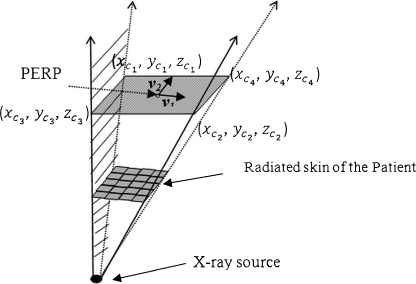
The origin is the X-ray source, and the base of the solid angle (cone for XRII pyramid for digital detectors) occurs at the patient entrance reference point (PERP). For a square-shaped field, the irradiated area will (Figure 10) depict an arbitrary surface area of the virtual patient surrounded by a pyramid-shaped field of radiation. The base of the pyramid is at the PERP distance (modified to be the projected s). Step 1 determines the total surface area lying within the projected field. The PERP plane (base of the pyramid) passes through PERP. The goal is to locate the four triangular faces to delineate an irradiated area on the patient.
Fig 10.
Inverted pyramid with base located at PERP. Each side of the pyramid intercepts the skin of the patient to parse those radiated sections of the skin.
First, we find two orthogonal vectors at PERP area as follows,
 |
14 |
 |
15 |
where v1 and v2 are parallel to the edges of the square field.
We denote the length of the side of the radiated area at PERP with l. The calculation for the coordinates of the four corners of the area is:
 |
16 |
 |
17 |
 |
18 |
 |
19 |
 |
20 |
With three points on each triangle face, we can construct the four faces of the pyramid such as  , where A, B, C, D are coefficients. As an example, for the plane consisting of source,
  and
and  coefficients of plane are as follows,
 |
21 |
 |
22 |
 |
23 |
 |
24 |
Coefficients of other planes can be computed accordingly.
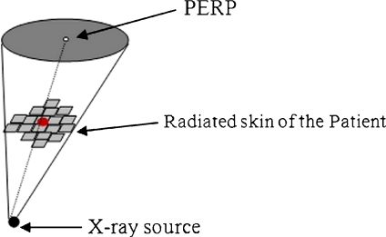
A conically shaped field having a circular base (at PERP) has a similar approach (Figure 11).
Fig 11.
Cone with circular base.
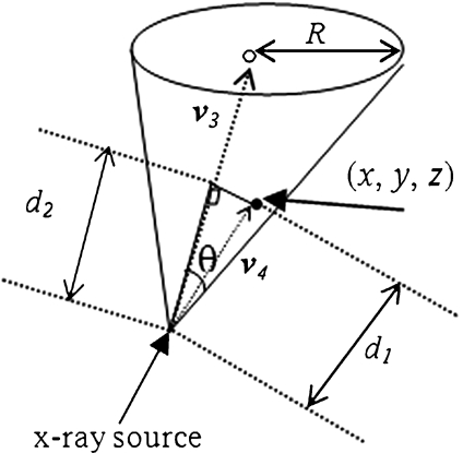
The vector v3 from X-ray tube to PERP as in Figure 12 is
 |
25 |
Fig 12.
Checking a point whether it is inside the cone or not.
Assume that (x, y, z) represents the coordinate of a point on the patient skin to be checked if it has been exposed or not. Figure 12 depicts the vector v4 and schematic of the feasibility method. The distance from this point to the source is computed as follows,
 |
26 |
 |
27 |
 |
28 |
Here,  means the l2 norm, that is,
The radius of the area at Patient Entrance Reference Point level;
 |
29 |
 |
30 |
For the two vectors, we have  , where θ is the angle between vector v3 and v4. Thus, any point on the patient skin, i.e., (x, y, z) satisfying
 |
31 |
is inside the cone and would have been radiated.
References
- 1.Food and Drug Administration: Public Health Advisory: Avoidance of Serious X-Ray-Induced Skin Injuries to Patients during Fluoroscopically-Guided Procedures. September 30, 1994.
- 2.Wagner LK, McNeese MD, Marx MV, Siegel EL. Severe skin reactions from interventional fluoroscopy: case report and review of the literature. Radiology. 1999;213:773–776. doi: 10.1148/radiology.213.3.r99dc16773. [DOI] [PubMed] [Google Scholar]
- 3.Ukisu R, Kushihashi T, Soh I. Skin injuries caused by fluoroscopically guided interventional procedures: case-based review and self-assessment module. American Journal of Radiology. 2009;193:59–69. doi: 10.2214/AJR.07.7140. [DOI] [PubMed] [Google Scholar]
- 4.Miller DL, Balter S, Noonan PT, Georgia JD. Minimizing radiation-induced skin injury in interventional radiology procedures. Radiology. 2002;225(2):329–36. doi: 10.1148/radiol.2252011414. [DOI] [PubMed] [Google Scholar]
- 5.Balter S, Miller D. The new Joint Commission sentinel event pertaining to prolonged fluoroscopy. Journal of the American College of Radiology. 2007;4(7):497–500. doi: 10.1016/j.jacr.2007.03.003. [DOI] [PubMed] [Google Scholar]
- 6.Joint Commission. Radiation Overdose as a Reviewable Sentinel Event. March 7, 2006. http://www.jointcommission.org/NR/rdonlyres/10A599B4-832D-40C1-8A5B-5929E9E0B09D/0/Radiation_Overdose.pdf
- 7.International Electrotechnical Commission. Medical electrical equipment—Part 2–54: Particular requirements for the basic safety and essential performance of X-ray equipment for radiography and radioscopy Geneva: IEC 60601-2-54; 2009.
- 8.Morrell RE, Rogers AT. A mathematical model for patient skin dose assessment in cardiac catheterization procedures. British Journal of Radiology. 2006;79:756–761. doi: 10.1259/bjr/57359387. [DOI] [PubMed] [Google Scholar]
- 9.Miller DL, Balter S, Cole PE, Lu HT, Berenstein A, Albert R, Schueler BA, Georgia JD, Noonan PT, Russell EJ, Malisch TW, Vogelzand RL, Geisinger M, Cardella JF, George JS, Miller GL, 3rd, Anderson J. Radiation doses in interventional radiology procedures: the RAD-IR study: part II: skin dose. Journal of Vascular and Interventional Radiology. 2003;14(8):977–990. doi: 10.1097/01.rvi.0000084601.43811.cb. [DOI] [PubMed] [Google Scholar]
- 10.Man-Systems Integration Standards. Revision B, NASA-STD-3000. Vol 1, July 1995.
- 11.Kerr GD, Hwang JML, JONES RM. A mathematical model of a phantom developed for use in calculations of radiation dose to the body and major internal organs of a Japanese adult. Journal of Radiation Research. 1976;17:211–229. doi: 10.1269/jrr.17.211. [DOI] [PubMed] [Google Scholar]
- 12.Eckerman CM. Specific Absorbed Dose Fractions of Energy at Various Ages from Internal Photon Sources. Appendix A: Description of the Mathematical Phantoms. ORNL/TM-8381/VI. Oak Ridge: Oak Ridge National Laboratory; 1987. [Google Scholar]
- 13.Digital Imaging and Communications in Medicine (DICOM) Supplement 4 X-Ray Angiographic Image Objects and Media Storage. Oct 9, 1996.
- 14.ICRU: International Commission on Radiation Units and Measurements. Patient Dosimetry for X–rays used in Medical Imaging. Journal of ICRU, 5, No 2, Report 74, Oxford University Press, 2005.
- 15.Wang S, Pavlicek W, Langer SG, Wu T, Zhang M, Morin RL, Hu M, Schueler BA. The ‘Dose Index Tracker’: An Automated Database of Patient Radiation Dose Records for Quality Monitoring. Journal of Digital Imaging, 2010 (in press). [DOI] [PMC free article] [PubMed]
- 16.Balter S. Capturing patient doses from fluoroscopically based diagnostic and interventional systems. Health Physics. 2008;95–5:535–540. doi: 10.1097/01.HP.0000327650.37315.2f. [DOI] [PubMed] [Google Scholar]
- 17.Ma C-M, Seuntjens JP. Mass-energy absorption coefficient and backscatter factor ratios for kilovoltage X-ray beams. Physics Medical Biology. 1999;44:131–143. doi: 10.1088/0031-9155/44/1/011. [DOI] [PubMed] [Google Scholar]
- 18.Mcparland BJ. Entrance skin dose estimates derived from dose–area product measurements in interventional radiological procedures. The British journal of Radiology. 1998;71:1288–1295. doi: 10.1259/bjr.71.852.10319003. [DOI] [PubMed] [Google Scholar]
- 19.Paden RG, Pavlicek W, Peter MB: Review of Cumulative Skin Dose in Estimation for Multi-episode Interventional Examinations. Proceedings of the 39th Midyear Topical Meeting, Medical and Laboratory Health Physics, Scottsdale, Arizona, 2006.


