Abstract
An integrated poly(dimethylsiloxane) (PDMS) membrane-based microfluidic emitter for high performance nanoelectrospray ionization-mass spectrometry (nanoESI-MS) has been fabricated and evaluated. The ~100-μm-thick emitter was created by cutting a PDMS membrane that protrudes beyond the bulk substrate. The reduced surface area at the emitter enhances the electric field and reduces wetting of the surface by the electrospray solvent. As such, the emitter enables highly stable electrosprays at flow rates as low as 10 nL/min, and is compatible with electrospray solvents containing a large organic component (e.g., 90% methanol). This approach enables facile emitter construction, and provides excellent stability, reproducibility and sensitivity, as well as compatibility with multilayer soft lithography.
INTRODUCTION
Miniaturization of analytical instrumentation has developed rapidly in recent years, and microfluidic devices have found increasing application in proteomics, metabolomics, and other biological analyses due to their ability to manipulate small volume samples or single cells and integrate multiple sample handling and separation steps in a nearly loss-free fashion.1–4 Meanwhile, electrospray ionization mass spectrometry (ESI-MS) has become an essential tool for biological analysis due to its high sensitivity and ability to detect and identify a large number of analytes while also providing structural information for detected species.5–6 The coupling of microfluidics with MS has thus gained broad interest,7 with nanoelectrospray ionization (nanoESI) providing the favored interface due to the general compatibility of microfluidics with low nanoliter-per-minute flow rates and the enhanced ionization efficiency achieved at such flows.8–10
Among the methods developed to couple microfluidics with nanoESI-MS, monolithic integration of the emitter is more favorable than, e.g., manually inserting capillary-based emitters due to improved reproducibility and the ability to eliminate dead volumes.11–12 Undoubtedly, the substrate material is of critical importance for the fabrication and electrospray performance of the integrated emitters. A number of materials have been employed to fabricate the integrated microfluidic electrospray devices, including glass,13–15 polyimide,16–17 and poly(dimethylsiloxane) (PDMS).18–26 PDMS is a widely used material for microfluidics due to its low cost, facile fabrication and chemical inertness. In addition, its hydrophobic surface significantly reduces surface wetting at the emitter with electrospray solvent, which can otherwise lead to unstable electrospray and preclude operation at nanoESI flow rates.13, 27
A number of methods have been developed to create PDMS microfluidic devices with integrated ESI emitters,18–26 but most have not been compatible with nanoelectrospray flow rates (e.g., <100 nL/min 10). In our previous approach, a razor blade was used to make two cuts through the substrates such that the device tapered to a ~2-mm-long vertical line with the microchannel terminating at the apex.19–21 These emitters were capable of producing stable electrosprays that operated in the cone-jet mode over a broad range of flow rates and ESI potentials.19 In addition, by extracting PDMS oligomers and other contaminants from the substrates and optimizing the angle of the taper, stable electrosprays at flow rates as low as 30 nL/min were demonstrated, and mass detection limits of ~80 zmol were achieved.20 However, because the line-shaped interface has a large emitter surface area compared with conventional tips, higher ESI voltages (3–4 kV) were required to achieve stable electrosprays, leading to greater likelihood of electrical breakdown. Also, solvents containing high organic content (e.g. > 50% methanol) tended to wet the surface, leading to unstable electrosprays.20 As such, applications requiring highly organic solvents, including gradient-elution reversed phase liquid chromatography (LC) separations, were incompatible with the interface.
In the present work, a new method to fabricate thin, planar PDMS microfluidic emitters has been developed based on spin-coated PDMS membranes. The emitters were created by cutting ~100 μm thick, microchannel-embedded membranes into a trianglular shape. The resulting emitters allow stable electrosprays at reduced potentials (~2 kV), reduced flow rates (10 nL/min), and are compatible with a broader range of solvents (up to 90% methanol). Moreover, excellent reproducibility, sustainability and sensitivity have all been demonstrated using this approach. The thin PDMS membranes used for emitter fabrication can also be used to incorporate pneumatically actuated valves, making this approach especially attractive for coupling complex, multilayer devices with MS detection.
EXPERIMENTAL SECTION
Materials
Leucine enkephalin, methionine enkephalin, porcine angiotensinogen 1–14, angiotensin I, apomyoglobin, hexamethyldisilazane (HMDS), and glacial acetic acid were purchased from Sigma-Aldrich (St. Louis, MO). HPLC-grade methanol was obtained from Fisher Scientific (Fair Lawn, NJ). PDMS elastomer base and curing agent were purchased as Dow Corning Sylgard 184 from Ellsworth Adhesives (Germantown, WI). Water was purified using a Barnstead Nanopure Infinity system (Dubuque, IA). Analyte was dissolved in the electrospray solvents, which were prepared by mixing water and methanol in different ratios (9:1, 7:3, 1:1, 3:7, and 1:9 (v/v)) and adding 0.1% (v/v) acetic acid.
Fabrication of the Membrane-Based Microfluidic ESI Emitter
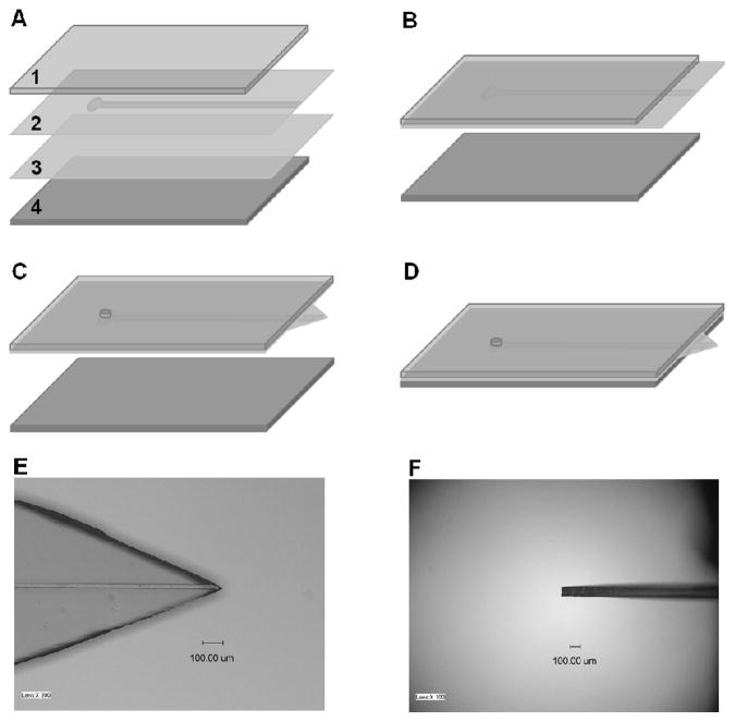
PDMS membrane-based microfluidic ESI emitters were fabricated using well established multilayer soft lithography techniques.28 A 4″ silicon wafer template containing 5 straight channels (50 μm wide and 25 μm high) was first created with SU-8 photoresist (Microchem, Newton, MA) using standard photolithography with a contact photomask aligner (NXQ4000-6, Neutronix-Quintel, Morgan Hill, CA). The photomask was designed using IntelliCAD software (IntelliCAD Technology Consortium, Portland, OR) and printed at 50,800 dpi at Fineline Imaging (Colorado Springs, CO). The surfaces of the patterned template and a bare silicon wafer were modified with HMDS using vapor deposition to assist in releasing the PDMS membranes from the wafers. A 10:1 weight ratio of PDMS base monomer to curing agent was then mixed, degassed under vacuum, spin coated on the two surface-modified wafers (patterned and bare) at 2000 rpm for 30 s (~50 μm final thickness), and cured in an oven at 75 °C for 2 h. The following procedure to fabricate the PDMS membrane-based microfluidic emitter is illustrated in Figure 1. A ~2-mm-thick PDMS slab (1) was bonded on the top of the patterned PDMS membrane (2), leaving a ~5-mm-long section of the channel uncovered. The substrates were then gently peeled from the patterned template and bonded with the unpatterned PDMS membrane (3) to enclose the microchannel (Figure 1B). After removing the assembly from the bare wafer, a through-hole was created at the end of the microchannel by punching the substrate with a manually sharpened syringe needle (NE-301PL-C; Small Parts, Miramar, FL), and a triangle shaped tip was generated by cutting the two-layer membrane vertically using a razor blade under a stereo microscope (Figure 1C). Finally, a PDMS slab (4) was bonded together with the assembly, leaving the sharp tip protruding out (Figure 1D). During the bonding procedures, all PDMS substrates were treated in oxygen plasma (PX-250; March Plasma Systems, Concord, CA) to achieve a covalent bond. Figures 1E and 1F are photographs of an emitter from the top view and side view, respectively. The emitter is approximately 100 μm thick, and the emitter angle is 45°. Following assembly, the devices were cured at 120 °C for at least 48 h to enhance cross-linking of oligomers that otherwise can contribute to the MS background.20
Figure 1.
(A–D) Fabrication of PDMS membrane based microfluidic ESI emitter. 1 and 4 are PDMS slabs. 2 and 3 are PDMS membranes with/without microstructures. (E) and (F) are photographs of a PDMS membrane based microfluidic ESI emitter from top view and side view, respectively.
Nanoelectrospray Ionization Mass Spectrometry
The nanoelectrospray performance of the PDMS membrane-based microfluidic emitter was investigated using an ion funnel-modified29 orthogonal time-of-flight MS instrument (G1969A LC/MSD TOF, Agilent Technologies, Santa Clara, CA). The microfluidic emitter was positioned 3 mm in front of the MS inlet capillary, which was heated to 120 °C. The sample was infused into the PDMS microchip from a 50 μL syringe (Hamilton, Reno, NV) via a fused silica capillary (75 μm i.d., 360 μm o.d., Polymicro Technologies, Phoenix, AZ) transfer line. The capillary end was inserted into a short Tygon tubing section (TGY-101-5C; Small Parts, Miramar, FL) and then inserted into the through-hole of the channel on the microchip. The infusion rate was controlled by a syringe pump (PHD 2000; Harvard Apparatus, Holliston, MA). The electrospray potential was applied on the syringe needle by a high-voltage power supply.
RESULTS AND DISCUSSION
The key strength of the integrated PDMS microfluidic interface with MS reported here is the sharp ESI emitter created by simply cutting the bonded PDMS membranes. The resulting membrane-based emitter size is decreased significantly compared with the previously reported interface, which tapered to a several mm long line.19 The dimension of the planar emitter described here depends on the thickness of the PDMS membranes and the emitter angle. Membrane thickness is mainly controlled by the spin-coating speed. Although much thinner membranes can be fabricated, the membranes employed in this work were approximately 50 μm thick with consideration of the emitter mechanical strength. The final emitter thickness was measured to be 92 ± 6 μm (based on 6 devices made from different batches) after bonding the two membrane layers, which is similar to the thin emitters fabricated from specially designed templates.22 The emitter angle is determined by the two vertical cuts, which can be guided by markers designed on the template.30 While smaller emitter angles might improve electrospray stability, difficulty in precise cutting and insufficient rigidity limited the emitter angle in this work to 30°–50°. During fabrication, the thick PDMS slabs are used to assist the manipulation of the thin membranes and impart rigidity to the final microdevices.
Direct infusion nanoESI-MS performance of the membrane-based PDMS microfluidic emitter was evaluated at different flow rates and electrospray potentials. For each flow rate, the ESI potential was increased by 100 V gradually and the associated mass spectrum was recorded for 5 min with a 1 Hz sampling rate. The relative standard deviation (RSD) of the total ion current (TIC) and the average signal intensity were calculated for each applied ESI potential. A sample plot, shown in Figure 2A for 200 nL/min infusion rate, indicates that at 2.1 kV, a plateau of maximum signal intensity and stable ion current (<2% RSD) is reached. Similar plots were obtained for flow rates ranging from 10 nL/min to 1 μL/min, and the corresponding ESI potential ranges for stable electrospray are shown in Figure 2B. While ESI potentials larger than 3 kV could still provide stable nanoESI for flow rates greater than 100 nL/min, the maximum potential was limited to 3.0 kV for these experiments. Importantly, the membrane-based emitter allowed us to achieve stable nanoelectropsprays at much lower potentials than before19 (i.e., ≤2.3 kV). The relatively small size of the membrane-based emitter enhances the electric field distribution around the tip so that sufficient electric field for stable spray is achieved at lower potential.31 In addition, stable nanoESI could be obtained at lower flow rates when using the membrane-based emitter. Figure 2C shows the TIC of 1 μM leucine enkephalin in 10% methanol solvent when infused at 10 nL/min, providing an RSD of 3.5%. Compared with capillary emitters, this membrane-based emitter achieves stable spray over a broader range of flow rates and applied potentials.19
Figure 2.
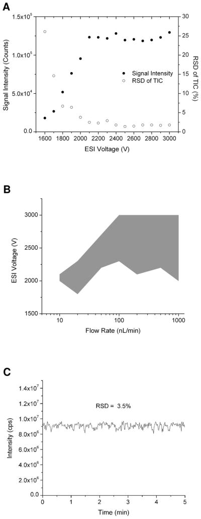
(A) Measurement of MS signal intensity and relative standard deviation (RSD) of total ion current (TIC) of 1 μM leucine enkephalin solution at different ESI voltages using the PDMS membrane based ESI emitter. The infusion rate was 200 nL/min. (B) Increased ranges of voltage and flow rate providing a stable electrospray using the membrane based microfluidic ESI emitter. (C) Total ion current of 1 μM leucine enkephalin solution at 10 nL/min. The applied ESI voltage was 2.1 kV.
Another characteristic of the PDMS membrane-based emitter is its compatibility with electrospray solvents having a large organic component as desired for, e.g., coupling with gradient LC separations. While the previous thick PDMS emitters were sufficiently hydrophobic to maintain a well defined Taylor cone with mostly aqueous solvents, surface wetting destabilized the spray for higher fraction organic solvents (i.e., >50% methanol). With the present design, due to the smaller emitter size (similar to the liquid Taylor cone dimension19) and the enhanced electric field distribution at the tip, the membrane-based emitter can maintain stable nanoelectrosprays (~3.5% RSD) with solvents containing 90% methanol (Figure 3A). A direct comparison of electrospray performance between the new membrane-based emitters and the previous ‘thick’ PDMS emitters with different solvent compositions is shown in Figures 3B and 3C. At 10% methanol concentration, their electrospray performance in terms of both signal intensity and stability is similar, but the performance diverges substantially as the organic component increases. The reduced dependence on a hydrophobic surface with the membrane-based emitter also helps to improve the reliability and longevity of the emitters, where over long periods of operation the hydrophobicity of the surface may decrease due to salt deposits, etc. To evaluate this, we treated the surface of an emitter with an oxygen plasma to render it extremely hydrophilic and infused sample in a 10% methanol solution at 100 nL/min. While the required voltage increased from 2 to 3 kV and the RSD increased from 2.0 to 6.8%, we were able to generate electrosprays where this was not possible using the previous design. In addition, the emitter could be restored to its original performance by placing it in an oven overnight at 120 °C (to recover its hydrophobicity).
Figure 3.
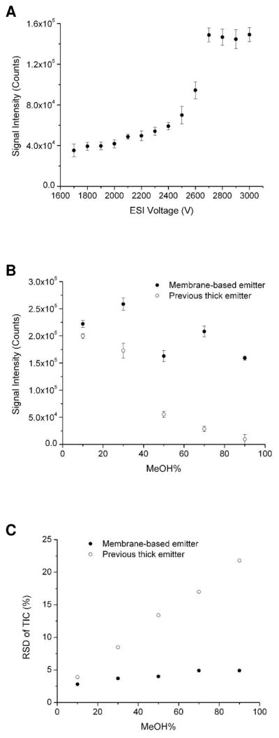
(A) Plot of MS signal intensity of 1 μM leucine enkephalin solution at different ESI voltages using the PDMS membrane based microfluidic ESI emitter. The ESI solvent was methanol: water: acetic acid = 90: 10: 0.1 (v/v). The infusion flow rate was 100 nL/min. (B) and (C) Comparisons of MS signal intensity and stability between PDMS membrane-based microfluidic ESI emitter and the previous thick PDMS microfluidic ESI emitter at different methanol contents in the ESI solution, respectively.
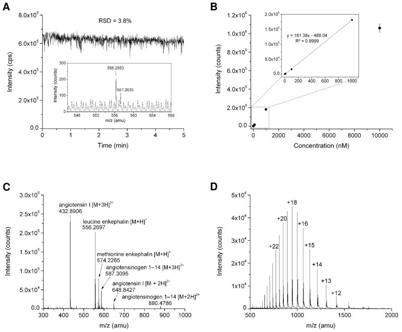
The membrane-based PDMS microfluidic emitter demonstrated excellent stability, durability, and reproducibility. For example, a membrane-based emitter was employed for direct-infusion ESI-MS under different conditions for at least 6 hours over a 6 day period, and a sample of leucine enkephalin was infused each day to test the emitter performance. The averaged MS signal intensities and RSDs of TIC for 5 min acquisition time in six continuing days are shown in Figure 4A. The small variation in RSD and the minimal drift in average signal intensity demonstrate stable electrospray performance over an extended period. Figure 4B shows a TIC of 2.5 hours infusion of angiotensin I in 10% methanol ESI solvent, which demonstrates a quite stable spray with RSD of 2.5%. This PDMS membrane-based emitter also has good reproducibility. Figure 4C shows the TICs of three emitters fabricated in the same batch under the same electrospray conditions. They performed in a highly similar fashion in terms of the MS signal intensity and stability. Similarly, this membrane-based emitter provides great batch-to-batch reproducibility (Figure 4D). Perhaps most importantly, nanoESI-MS detection sensitivity is significantly improved ~10-fold compared with the previous thick PDMS emitter20 and 1 nM leucine enkephalin was easily detected (Figure 5A). Figure 5B shows the MS signal intensity of leucine enkephalin at different concentrations (1 nM to 10 μM). A linear dynamic range was achieved from 1 nM to 1 μM. The membrane-based emitter was used to spray different kinds of samples, such as a peptide mixture (Figure 5C) and a protein (Figure 5D).
Figure 4.
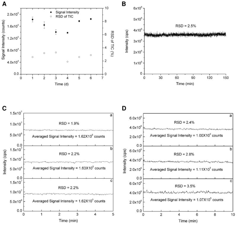
Characterization of the PDMS membrane based microfluidic ESI emitter stability and reproducibility. (A) RSD of TIC and signal intensity of infused 1 μM leucine enkephalin in 10% methanol ESI solvent during continuous 6 days operation. (B) TIC of infused 1 μM angiotensin I in a 2.5h run. (C) Emitter-to-emitter reproducibility in the same batch with infusion of 1 μM leucine enkephalin. (D) Batch-to-batch reproducibility with infusion of 1 μM angiotensin I. In all experiments, the infusion flow rate was 100 nL/min, and the applied ESI potential was 2.5 kV.
Figure 5.
(A) Total ion trace of 1 nM leucine enkephalin solution using PDMS membrane based ESI emitter. Inset is the averaged mass spectra in a period of 1 min. The infusion flow rate was 100 nL/min and the applied ESI voltage was 2.8 kV. (B) The averaged signal intensity of leucine enkephalin at different concentrations. (C) and (D) Mass spectra of a mixture containing four peptides (1 μM) and apomyoglobin (1 μg/μL), respectively. The infusion flow rate was 100 nL/min and the applied ESI voltage was 2.5 kV.
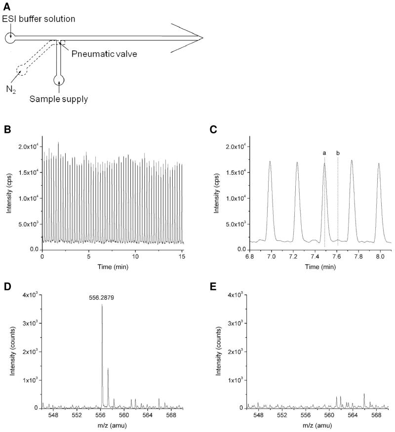
The emitter described here is also attractive for its ability to easily integrate MS analysis with complex, multilayer microfluidics, as the thin membranes used for emitter fabrication also enable pneumatic valve incorporation.28 As a simple example, we incorporated a pneumatic valve at a T-intersection with a nanoESI interface to perform rapid serial analyte injections as shown in Figure 5. The pneumatic valve is employed to control the injection of sample solution into the main channel and is operated by a valve control system described elsewhere.32 Sample injection is driven by a constant pressure, and the ESI buffer is infused through the main channel toward the ESI emitter by a syringe pump. The ESI potential is applied on the syringe needle to maintain stable electrospray. Approximately 500 pL of sample is injected into the main channel during the 100 ms valve opening step, which is then delivered to the emitter for electrospray and detected by MS. Figure 5B shows repeated MS peaks of leucine enkephalin with injection interval of 15 s. A clear view of 5 peaks is zoomed in Figure 5C. The mass spectrum of the peak (a) and the baseline (b) between adjacent peaks are shown in Figures 5D and 5E, respectively. Beyond controlled-volume sample injections, the membrane-based emitter will facilitate the application of MS to other areas that employ multilayer soft lithography, including droplet-based microfluidics30, 33–34 and chemical cytometry.35
CONCLUSIONS
A new PDMS membrane-based microfluidic emitter for nanoESI-MS has been demonstrated. The relatively sharp emitter was fabricated by cutting the thin PDMS membrane easily into a triangle shape, which could enhance the electric field distribution at the tip and reduce the emitter surface wetting issue significantly. The emitter allows stable nanoESI at lower ESI potentials, reduced flow rates, and is compatible with a broader range of electrospray solvents. The emitter has good stability, reproducibility, and high sensitivity. It can be operated stably over long periods of time, and recovered by treating at high temperature. This membrane-based ESI emitter enables convenient integration with on-chip separations (e.g. microchip CE) for MS detection and multilayer PDMS microfluidic devices, such as pneumatic valve-integrated microchips.
Figure 6.
(A) Design of a multilayer microfluidics which is integrated with a pneumatic valve to control sample injection and a membrane-based ESI emitter. (B) MS detection of repeated 1 μM leucine enkephalin sample injection. ESI potential: 2.5 kV; ESI buffer flow rate: 200 nL/min; valve actuation frequency: 0.07 Hz. (C) Detailed view of the MS detected leucine enkephalin peaks. (D) and (E) Mass spectrum of the peak (a) and the baseline (b) indicated in Figure 5C, respectively.
Acknowledgments
We thank Dr. Ioan Marginean for helpful discussions. Portions of this research were supported by the U.S. Department of Energy (DOE) Office of Biological and Environmental Research, and the NIH National Center for Research Resources (RR018522). This research was performed in the Environmental Molecular Sciences Laboratory (EMSL), a U.S. DOE national scientific user facility located at the Pacific Northwest National Laboratory (PNNL) in Richland, WA. PNNL is a multiprogram national laboratory operated by Battelle for the DOE under Contract No. DE-AC05-76RLO 1830.
References
- 1.Huang B, Wu H, Bhaya D, Grossman A, Granier S, Kobilka BK, Zare RN. Science. 2007;315:81–84. doi: 10.1126/science.1133992. [DOI] [PubMed] [Google Scholar]
- 2.Peterson DS, Rohr T, Svec F, Fréchet JMJ. Anal Chem. 2002;74:4081–4088. doi: 10.1021/ac020180q. [DOI] [PubMed] [Google Scholar]
- 3.Lazar IM, Trisiripisal P, Sarvaiya HA. Anal Chem. 2006;78:5513–5524. doi: 10.1021/ac060434y. [DOI] [PubMed] [Google Scholar]
- 4.Mellors JS, Jorabchi K, Smith LM, Ramsey JM. Anal Chem. 2010;82:967–973. doi: 10.1021/ac902218y. [DOI] [PMC free article] [PubMed] [Google Scholar]
- 5.Aebersold R, Mann M. Nature. 2003;422:198–207. doi: 10.1038/nature01511. [DOI] [PubMed] [Google Scholar]
- 6.Liu T, Belov ME, Jaitly N, Qian W-J, Smith RD. Chem Rev. 2007;107:3621–3653. doi: 10.1021/cr068288j. [DOI] [PMC free article] [PubMed] [Google Scholar]
- 7.Oleschuk RD, Harrison DJ. Trends Anal Chem. 2000;19:379–388. [Google Scholar]
- 8.Smith RD, Shen Y, Tang K. Accounts Chem Res. 2004;37:269–278. doi: 10.1021/ar0301330. [DOI] [PubMed] [Google Scholar]
- 9.El-Faramawy A, Siu KWM, Thomson BA. J Am Soc Mass Spectrom. 2005;16:1702–1707. doi: 10.1016/j.jasms.2005.06.011. [DOI] [PubMed] [Google Scholar]
- 10.Schmidt A, Karas M, Dülcks T. J Am Soc Mass Spectrom. 2003;14:492–500. doi: 10.1016/S1044-0305(03)00128-4. [DOI] [PubMed] [Google Scholar]
- 11.Koster S, Verpoorte E. Lab Chip. 2007;7:1394–1412. doi: 10.1039/b709706a. [DOI] [PubMed] [Google Scholar]
- 12.Gibson GTT, Mugo SM, Oleschuk RD. Mass Spectrom Rev. 2009;28:918–936. doi: 10.1002/mas.20248. [DOI] [PubMed] [Google Scholar]
- 13.Xue Q, Foret F, Dunayevskiy YM, Zavracky PM, McGruer NE, Karger BL. Anal Chem. 1997;69:426–30. doi: 10.1021/ac9607119. [DOI] [PubMed] [Google Scholar]
- 14.Ramsey RS, Ramsey JM. Anal Chem. 1997;69:1174–1178. doi: 10.1021/ac971475k. [DOI] [PubMed] [Google Scholar]
- 15.Mellors JS, Gorbounov V, Ramsey RS, Ramsey JM. Anal Chem. 2008;80:6881–6887. doi: 10.1021/ac800428w. [DOI] [PMC free article] [PubMed] [Google Scholar]
- 16.Gobry V, Oostrum JV, Martinelli M, Rohner TC, Reymond F, Rossier JS, Girault HH. Proteomics. 2002;2:405–412. doi: 10.1002/1615-9861(200204)2:4<405::AID-PROT405>3.0.CO;2-Y. [DOI] [PubMed] [Google Scholar]
- 17.Rossier JS, Youhnovski N, Lion N, Damoc E, Becker S, Reymond F, Girault HH, Przybylski M. Angew Chem Int Ed. 2003;42:54–58. [PubMed] [Google Scholar]
- 18.Kim JS, Knapp DR. J Am Soc Mass Spectr. 2001;12:463–469. doi: 10.1016/S1044-0305(01)00219-7. [DOI] [PubMed] [Google Scholar]
- 19.Kelly RT, Tang K, Irimia D, Toner M, Smith RD. Anal Chem. 2008;80:3824–3831. doi: 10.1021/ac8000786. [DOI] [PMC free article] [PubMed] [Google Scholar]
- 20.Sun X, Kelly RT, Tang K, Smith RD. Analyst. 2010;135:2296–2302. doi: 10.1039/c0an00253d. [DOI] [PMC free article] [PubMed] [Google Scholar]
- 21.Iannacone JM, Jakubowski JA, Bohn PW, Sweedler JV. Electrophoresis. 2005;26:4684–4690. doi: 10.1002/elps.200500498. [DOI] [PubMed] [Google Scholar]
- 22.Svedberg M, Veszelei M, Axelsson J, Vangbo M, Nikolajeff F. Lab Chip. 2004;4:322–327. doi: 10.1039/b402490g. [DOI] [PubMed] [Google Scholar]
- 23.Lindberg P, Dahlin AP, Bergström SK, Thorslund S, Andrén PE, Nikolajeff F, Bergquist J. Electrophoresis. 2006;27:2075–2082. doi: 10.1002/elps.200500763. [DOI] [PubMed] [Google Scholar]
- 24.Huikko K, Östman P, Grigoras K, Tuomikoski S, Tiainen VM, Soininen A, Puolanne K, Manz A, Franssila S, Kostiainen R, Kotiaho T. Lab Chip. 2003;3:67–72. doi: 10.1039/b300345k. [DOI] [PubMed] [Google Scholar]
- 25.Dahlin AP, Wetterhall M, Liljegren G, Bergström SK, Andrén P, Nyholm L, Markides KE, Bergquist J. Analyst. 2005;130:193–199. doi: 10.1039/b414592e. [DOI] [PubMed] [Google Scholar]
- 26.Thorslund S, Lindberg P, Andrén PE, Nikolajeff F, Bergquist J. Electrophoresis. 2005;26:4674–4683. doi: 10.1002/elps.200500338. [DOI] [PubMed] [Google Scholar]
- 27.Rohner TC, Rossier JS, Girault HH. Anal Chem. 2001;73:5353–5357. doi: 10.1021/ac015557r. [DOI] [PubMed] [Google Scholar]
- 28.Unger MA, Chou H-P, Thorsen T, Scherer A, Quake SR. Science. 2000;288:113–116. doi: 10.1126/science.288.5463.113. [DOI] [PubMed] [Google Scholar]
- 29.Kelly RT, Tolmachev AV, Page JS, Tang K, Smith RD. Mass Spectrom Rev. 2010;29:294–312. doi: 10.1002/mas.20232. [DOI] [PMC free article] [PubMed] [Google Scholar]
- 30.Kelly RT, Page JS, Marginean I, Tang K, Smith RD. Angew Chem, Int Ed. 2009;48:6832–6835. doi: 10.1002/anie.200902501. [DOI] [PMC free article] [PubMed] [Google Scholar]
- 31.Maxwell EJ, Zhong X, Chen DDY. Anal Chem. 2010;82:8377–8381. doi: 10.1021/ac1017953. [DOI] [PubMed] [Google Scholar]
- 32.Sun X, Kelly RT, Danielson WF, III, Agrawal N, Tang K, Smith RD. Electrophoresis. 2011 doi: 10.1002/elps.201000522. in press. [DOI] [PMC free article] [PubMed] [Google Scholar]
- 33.Galas JC, Bartolo D, Studer V. New Journal of Physics. 2009;11:075027. [Google Scholar]
- 34.Zeng S, Li B, Su X, Qin J, Lin B. Lab Chip. 2009;9:1340–1343. doi: 10.1039/b821803j. [DOI] [PubMed] [Google Scholar]
- 35.Wu H, Wheeler A, Zare RN. Proc Natl Acad Sci USA. 2004;101:12809–12813. doi: 10.1073/pnas.0405299101. [DOI] [PMC free article] [PubMed] [Google Scholar]


