Abstract
Purpose: Parallel magnetic resonance imaging (MRI) requires an array of RF coil elements with different sensitivity distributions and with minimal electromagnetic coupling. The goal of this project was to develop a new method based on induced current compensation or elimination (ICE) for improved coil element decoupling and to investigate its performance in phantom MR images.
Methods: An electromagnetic decoupling method based on induced current compensation or elimination for nonoverlapping RF coil arrays was developed with the design criteria of high efficiency, easy implementation, and no physical connection to RF array elements. An eigenvalue/eigenvector approach was employed to analyze the decoupling mechanism and condition. A two-channel microstrip array and an eight-channel coil array were built to test the performance of the method. Following workbench tests, MR imaging experiments were performed on a 7T MR scanner.
Results: The bench tests showed that both arrays achieved sufficient decoupling with a S21 less than −25 dB among the coil elements at 298 MHz. The MR phantom images demonstrated well-defined sensitivity distributions from each coil element and the unique decoupling capability of the proposed ICE decoupling technique. B1 distributions of the individual elements were also measured and calculated.
Conclusions: The theoretical analysis and experiments demonstrated the feasibility of the decoupling method for high field RF coil array designs without overlapping or direct physical connections between coil elements, which provide more flexibility for coil array design and optimization. The method offers a new approach to address the RF array decoupling issue, which is a major challenge in implementing parallel imaging.
Keywords: phased array, decoupling, induced current compensation, ultra high field, parallel MRI
INTRODUCTION
Parallel imaging using an array of RF receivers or coils is a well established fast magnetic resonance imaging method, which can dramatically reduce the minimum data acquisition time by replacing phase-encoding steps with the encoding inherent in the sensitivity profiles of the coil array elements.1, 2, 3, 4, 5, 6 For spin excitation, parallel transmit or parallel excitation (with an array of RF transceiver coils) is essential for achieving fast excitation,7 perform efficient B1 shimming, and manipulate the B1 distribution, particularly for high and ultrahigh field MR applications in humans, where the image homogeneity becomes problematic.8 A major challenge in implementing parallel imaging or parallel excitation is the design of the RF receiver or transceiver arrays. Eliminating strong electromagnetic coupling among the resonant elements in a coil array is critical to the efficiency of the coil arrays and the performance of parallel imaging. Especially for higher channel count array designs, which are often needed to gain increased imaging acceleration, decoupling the densely-packed resonant elements from each other becomes progressively difficult. Overlapping coil elements (i.e., geometric decoupling), capable of achieving excellent decoupling for two adjacent elements, is a commonly-used decoupling technique for loop-type coil arrays.9 However, overlapping the coils decreases parallel imaging performance by degrading the geometry (g-) factor in the overlapping area of sensitivity. Technically, a nonoverlapped array design is often desired for current parallel imaging techniques to enable faster imaging while maintaining higher SNR and reduced artifacts.10 The preamplifier decoupling method can alleviate the mutual coupling in receiver arrays,9 however, it is not readily feasible in transceiver arrays.11 Capacitive and inductive decoupling networks introduced between two adjacent coil elements are often employed to compensate for the mutual coupling.12, 13, 14, 15, 16, 17 This method requires a dedicated circuit connecting adjacent coil with lumped L/C elements whose values can become impractically small especially at ultrahigh magnetic fields.17 Another promising technique is to use the microstrip transmission line which demonstrates a broadband decoupling capability if the decoupling conditions can be satisfied.18, 19, 20 In addition, a MR sample can also alter the decoupling performance in a coil array. The sample can be modeled using an untunable circuit between the array elements to analyze its effects on the decoupling performance.21
In this work, we aimed to develop a new decoupling method based on an induced current compensation concept suitable for nonoverlapped coil arrays. The induced current is compensated by an independent decoupling element which can be an inductive loop, lumped-element resonator, or a microstrip resonator.22 This method is capable of decoupling strongly coupled elements in massive coil arrays at high and ultrahigh fields. In addition, this method differs from prior approaches, e.g., L/C decoupling networks. There is no physical connections between the decoupling elements and coil array elements, which facilitate flexible transceiver array designs.23 An eigenvalue/eigenvector analysis method is applied for analyzing the decoupling mechanism and calculating the decoupling conditions. Two phased array coils, a two-channel microstrip array and an eight-channel surface coil array, were designed and fabricated to investigate the performance of the new decoupling method. Bench tests and preliminary MR phantom imaging results are shown using the coil arrays decoupled by the new method at 7T.
MATERIALS AND METHODS
Eigenvalue∕eigenvector analysis
The main purpose of the decoupling elements is to compensate or eliminate the induced current among coil elements due to mutual coupling. In specific circumstances, the induced currents in one coil element from other coil elements in an array can be made equal to the induced currents from decoupling elements, leading to effective decoupling of the array elements.24, 25 To investigate the decoupling potential, the eigenvalue/eigenvector analysis which has been widely used in volume coil designs was applied. Different eigenvalues and eigenvectors represent different modes and magnetic field distributions of coils. The eigenvalue and orthogonal eigenvectors representing the current in the coil elements of the array coils are chosen so as to satisfy the decoupling condition.
Consider a coil array consisting of two coil elements and one decoupling element. Based on the Kirchhoff’s voltage law (KVL), under resonance the currents in the array and decoupling element satisfy
| (1) |
where X1, and X2 are the impedances of coil element 1, and coil element 2, respectively, which are generally determined by coil element inductance L and tuning capacitance C, Xd is the impedance of decoupling element which is inductive generally, Xij (i, j = 1, 2, d) are the mutual impedance, and I1, I2, and Id are the current of coil element 1, coil element 2, and decoupling element, respectively. One of the eigenvalues of the impedance matrix X is 0 when
| (2) |
The eigenvectors along with eigenvalue 0 are [1,0,-X21/X23] and [0,1,-X12/X13], which correspond to that the current of coil element 1 and coil element 2 are orthogonal and decoupled to each other under this condition. The resonance frequency can be calculated by
| (3) |
Since the impedance of each coil element is approximately equal in most array coils, if the decoupling element is placed symmetrically between coil elements, the mutual inductance between the decoupling element and each coil element are the same as well, and Eq. 2 can be written as
| (4) |
which is consistent with our previous work.24 The analysis in Eq. 1 would be frequency insensitive as long as the mutual inductance is frequency insensitive. For a specific coil structure, there is a defined best-decoupling condition for a specific resonance frequency due to the different mutual inductance at the different frequency. In cases where the mutual inductance does not vary significantly over limited frequency range (e.g., microstrip coils), the decoupling method could provide usable decoupling performance.14, 18, 26
This decoupling method is also feasible for arrays consisting of three element coils or more. The eigenvalue/eigenvector analysis of an n-element array with (n-1) decoupling elements can be found in the Appendix. The decoupling condition dictates that all the decoupling elements contribute to the decoupling between any two of the coil elements, which means the global effect of each decoupling element should be considered. However, the contribution of each decoupling element depends on the mutual inductance between the decoupling element and the two coil elements. This indicates that the contribution of one decoupling element to non adjacent coils could be ignored as long as the mutual inductance between the decoupling element and the non adjacent coil element is negligible, which indeed is the case in this study. The mutual inductance matrix of the decoupling elements and the coil elements (Xcd in Appendix) should be adjusted in order to assure the existence of the inversion of matrix Xcd. If the Xd does not satisfy the decoupling condition or/and the inversion of matrix Xcd does not exist, an additional decoupling element is required.
The eigenvalue/eigenvector analysis only uses mutual inductance since the mutual inductance is dominant when analyzing the induced current from other coil elements and decoupling elements. As mentioned in previous work,9 ignoring the effect of the mutual resistance will not lead to significant SNR reduction.
Two-channel microstrip array
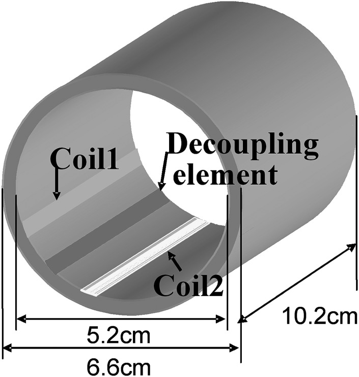
The concept of induced current elimination (ICE) decoupling generated by a decoupling element is experimentally demonstrated with a microstrip array consisting of two microstrip coil elements and one microstrip decoupling element. As shown in Fig. 1, both of the coil elements and the decoupling element were built on a Teflon cylinder with 6.6 cm outer diameter, 5.2 cm inner diameter and 10.2 cm length. The gap between the coil elements was 2 cm. The decoupling element is a copper tape with 6.35 mm width and 102 mm length, which is terminated with trimmer capacitors (9620, Johanson Mfg, Boonton, NJ). The decoupling element is placed between two coil elements. The Teflon substrate is 7 mm thick. The coil elements were tuned to 298.144 MHz, corresponding to the proton Larmor frequency of the 7T scanner, by the capacitors on both ends and matched to 50 Ω. The decoupling elements were tuned to satisfy the decoupling condition. Bench tests on the resonant modes and isolation between two coil elements with and without the decoupling element were performed using a network analyzer (Agilent E5070B).
Figure 1.
Configuration of a two-channel microstrip array coil with an induced current compensation decoupling element. This model was used to investigate and validate the proposed induced current compensation decoupling method. The coil array elements are microstrip resonators with capacitive terminations.
The MR imaging performance of the array with the proposed ICE decoupling technique was verified on a GE 7T/90cm magnet (GE Healthcare, Waukesha, WI). A water phantom was employed to test the isolation between the two coil elements. Gradient echo images in axial orientation were acquired using the two coil elements of the array simultaneously. The imaging parameters were: TR = 30 ms, TE = 6.8 ms, thickness = 3 mm, flip angle = 20°, and FOV = 10 × 10 cm.
To assure the performance of the proposed decoupling method, a pattern comparison of images acquired with: (1) single coil element (without the adjacent coil element); (2) one coil element under weakly coupled; and (3) well-decoupled condition; was performed using a gradient echo sequence with identical imaging parameters.
Eight-channel surface coil array
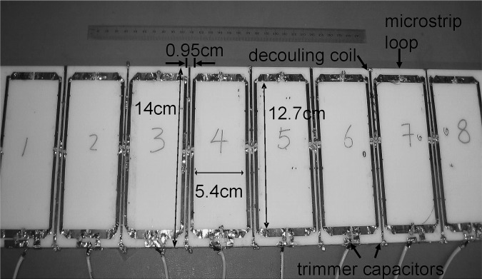
In order to further validate the feasibility and performance of the proposed decoupling method for coil arrays with more than two elements, an eight-channel (i.e., eight-element) surface coil array using the proposed decoupling technique was built on an acrylic board with a thickness of 0.95 cm. As shown in Fig. 2, eight of the 5.4 × 12.7 cm2 microstrip loop coil elements built with 0.32 cm width copper strips, were closely placed with 0.95 cm gaps. This arrangement of closely placed elements would help to improve image coverage but also create a strong mutual coupling among the coil elements. The coil elements were tuned to 298.144 MHz and matched to 50 Ω. The insulation layer between the coil array and the water phantom was of 2.54 cm thickness. Between two adjacent loops, microstrip lines with 14 cm length and 0.32 cm width were fabricated to minimize the coupling between the loop coils. The decoupling microstrip lines were capacitively terminated at their ends. The decoupling elements were first tuned to decouple the two adjacent coil elements. Then several iterations were carried out to fine tune the decoupling elements to optimize decoupling.
Figure 2.
7T loop-type microstrip coil array consisting of eight loop elements (dimensions of each: 12.7 × 5.4 cm) and seven proposed decoupling elements. To test the decoupling capability of the proposed induced current compensation decoupling technique, the loop elements were densely-placed with a gap of only 0.95 cm between adjacent loops, resulting in strong coupling between elements.
The MRI phantom experiments were performed on a GE 7T/90 cm whole body magnet. The water phantom was a cylinder with a dimension of 6.35 cm outer diameter and 50.8 cm length. Gradient echo images in sagittal orientation were acquired using the designed array coil. Acquisition parameters were: TR = 100 ms, TE = 1.1 ms, sampling bandwidth = 62.5 kHz, thickness = 5 mm, flip angle = 30°, FOV = 35 cm, and imaging matrix = 256 × 256.
To validate the effectiveness of the new decoupling method, a comparison of the sensitivity pattern and B1 distribution between the individual elements (i.e., without adjacent elements or decoupling elements) and decoupled array elements was performed. In this comparison, water images of the individual elements were separately acquired using exactly the same experiment setup (gradient echo sequence, imaging parameters, etc.), as that used for testing the decoupled array as a whole. The sensitivity pattern comparison was performed using the double-angle method.27, 28, 29, 30
RESULTS
Workbench study
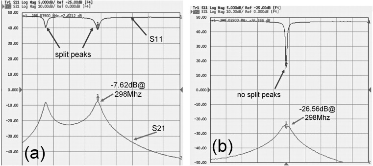
In Fig. 3a, the split peaks and S21 = −7.62 dB at 298 MHz indicate strong coupling between the two microstrip coil elements without the decoupling element. When the decoupling element was applied, no resonant peak splitting was observed for either coil elements. The decoupling between the two coil elements was −26.6 dB at 298 MHz and the coupling was reduced over a relatively broad bandwidth as shown in Fig. 3b, compared with that without the decoupling element in Fig. 3a. These results demonstrated that the two coil elements of the array were decoupled sufficiently. The mutual inductance between the coil elements is approximately 1.0 nH, while the mutual inductance between the coil element and the decoupling element is approximately 3.7 nH.
Figure 3.
S11 and S21 of the two element array coil, (a) without decoupling element; (b) with the induced current compensation decoupling element. Greater than −26 dB isolation between the two resonant elements was achieved by using the proposed induced current compensation decoupling method.
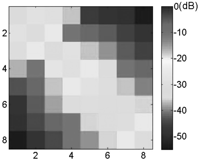
For the eight-channel coil array, isolation between the two adjacent elements of −25 dB or better was achieved by adjusting the capacitors of decoupling microstrip lines. The Q value of each coil element of the eight-channel coil array measured approximately 180. For the two-element microstrip array, no resonant peak split was observed from any coil element. The S11 and S21 matrix of the eight-element array was measured as shown in Fig. 4. The matrix showed that all elements of the array were matched to 50 Ω with S11 better than −29 dB and the isolation between any two coil elements was better than −25 dB. This indicates that the eight channels were well decoupled even though the mutual inductance between coils was relatively large, due to the size of coil loops and the small distance between adjacent coils. In the eight-element array design, there were two capacitors in each decoupling element, with one located at the center, and the other located at one end of the element. The values of these capacitors are approximately 16 pF for the center ones and 23 pF for the end ones.
Figure 4.
S11 and S21 measurement of eight-element plane array. The isolation between any two resonant elements was better than −25 dB, demonstrating excellent decoupling capability for the proposed induced current compensation decoupling method in multi-element coil arrays.
MR phantom imaging
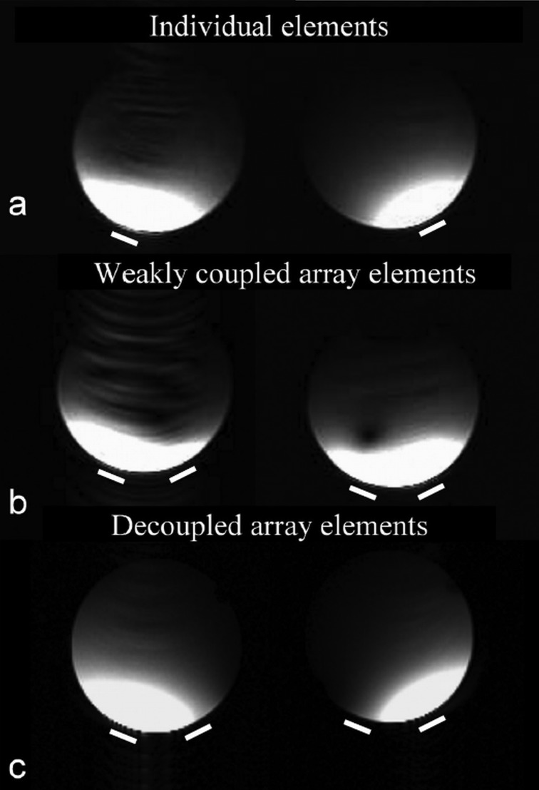
Figure 5 shows water phantom images acquired from (a) individual elements, (b) elements of weakly decoupled array, and (c) elements of the well decoupled coil array at 7T. Compared with the individual element images, the patterns of well decoupled coil array were similar and no signal was observed from adjacent elements. The well-defined image profiles from each coil element demonstrate that the proposed decoupling technique performed effectively and as expected at the ultrahigh field of 7 T. The artifact in the left image of Fig. 5b was possibly caused by gradient system instability.
Figure 5.
Water phantom images acquired by using (a) individual elements, (b) element 1 and element 2 of weakly decoupled (−10.3 dB) array, and (c) element 1 and element 2 of the well decoupled (better than −26 dB) coil array at 7T. The two lines beneath the images indicate the relative positions of the two coil elements. Imaging parameters were as follows: TR = 30 ms, TE = 6.8 ms, slice thickness = 3 mm, flip angle = 20°, FOV = 10 cm. Excellent performance for the induced current compensation decoupling technique was demonstrated by well-defined image profiles from each coil element and the image similarity between the individual element acquisition and that using the decoupled array.
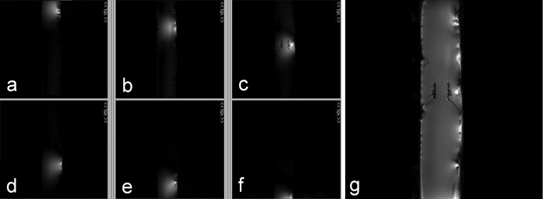
Figures 6a, 6b, 6c, 6d, 6e, 6f shows the images obtained from six elements of the eight-channel surface coil array, in which no signal was observed from other elements when using individual elements, demonstrating excellent decoupling performance for the ICE decoupling method. The other two elements of the eight-element array were outside the maximum FOV which was by the linear-region of the gradient coils on our 7T system. Figure 6g shows the whole phantom image reconstructed using the sum of squares method. The images demonstrated excellent decoupling performance for the eight-channel coil array using this new decoupling method at the ultrahigh field of 7 T.
Figure 6.
MR images demonstrating the performance of the induced current compensation decoupling method. (a)–(f) Water phantom (6.35 cm in diameter by 50.8 cm in length) gradient echo images were acquired using the six elements (or channels) of the induced current compensation decoupled microstrip coil array as shown in Fig. 2. Imaging parameters: TR = 100 ms, TE = 1.1 ms, slice thickness = 5 mm, flip angle = 30°, FOV = 35 cm; (g) the reconstructed image using the sum of squares method shows the combined water phantom image using the new approach.
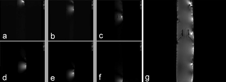
The water phantom images acquired by using individual coil elements are shown in Fig. 7. The high intensity spots (or “hot spots”) and the artifacts around them in Figs. 67 were caused by magnetic susceptibility effects in the phantom. The comparison results showed that the SNR patterns and the combined image quality of individual coil elements were similar with those of the decoupled eight-element array. These results demonstrate the feasibility of the ICE decoupling method.
Figure 7.
Water phantom images acquired by using individual elements (without adjacent elements and decoupling elements). The experiment setup, including the phantom used, imaging parameters and reconstruction method, was the same as that in the induced current compensation decoupling experiment shown in Fig. 6.
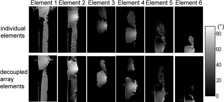
Figure 8 shows the B1 map comparison between individual elements and decoupled array elements. The “dielectric resonance” effect (or the wave behavior) for the water phantom at 7 T (which results in an enlarged imaging coverage) can be easily observed in some of the images, e.g., from element 1 and element 2. The B1 patterns of individual elements show a similar distribution between the isolated case and the decoupled experiments. These results demonstrate that the introduction of the decoupling elements did not alter the field distribution of the coil elements. The quality of the B1 map could be improved and the calculation error can be further reduced by more averages, which, however, leads to a longer scanning time. In the MR images of individual elements (Figs. 67), the profile of each element in the isolated case and the decoupled case was in better agreement than that suggested by the B1 maps.
Figure 8.
B1 map comparison between individual elements isolated (i.e. without adjacent elements and decoupling elements) and decoupled array elements using the induced current compensation method. The B1 maps are calculated by using double flip-angle method and scaled in angle. The dielectric resonance effects of water phantom at 7T were observed in these images especially slices from element 1 and 2.
Based on the comparative results, the images of individual elements indicate that the coil elements provide some overlap in image coverage. This overlap is desired for parallel imaging and parallel excitation. The signal intensity of the combined images is relatively uniform although not as good as with overlapping coils. This nonuniformity problem could potentially be improved by performing B1 shimming with this eight-element transceiver array.
DISCUSSION
The feasibility of a new induced current compensation decoupling method for parallel imaging RF coil arrays has been investigated through eigenvalue/eigenvector analysis and experimentally validated through bench tests and MR imaging experiments. The results showed that the method provided a novel approach for decoupling array coil elements that are not overlapped and without direct physical connections between coil elements. Compared with prior approaches using lumped L/C as decoupling elements, the absence of physical connections provides a mechanically robust method for decoupling flexible arrays. In addition, the method is capable of decoupling massive arrays wherein the elements are strongly coupled. The nonoverlapping characteristic can also avoid g-factor degradation and provides more flexibility for coil array design and optimization for ultrahigh field parallel imaging. The induced current compensation decoupling method presented here provides a potential decoupling solution for designing large-sized volume-type coil arrays for ultrahigh field head imaging as well.31
A microstrip has been chosen as a decoupling element in the present experiments because of its compact structure and space saving. However, other type of circuit configurations can be used as decoupling elements, as long as the mutual inductances satisfy the decoupling condition as derived in the theoretical analysis.
As mentioned in previous studies, the sample loading affects the mutual inductance of the coil and decoupling elements. However, the efficacy of the ICE decoupling technique is generally preserved when the coil is loaded by different samples. There is no need to retune the decoupling elements as long as the distance between coil and sample remains no change. In the extreme case, a fine retuning may be required to optimize the decoupling condition.
ACKNOWLEDGMENTS
The authors would like to thank J. Che for manuscript editing and proofreading. This work was partially supported by NIH Grant Nos. EB004453, EB008699 and EB007588-03S1, and a QB3 Research Award.
APPENDIX
Consider an n-element array, in which the coil elements are indicated as c1 to cn, with (n-1) decoupling elements which are indicated as d1 to dn-1 as an example. The circuit equation Eq. 1 can be written as
| (A1) |
where Ic and Id are the currents in the coil elements and decoupling elements respectively,
| (A2) |
Xc and Xd are the impedance matrix of the coil elements and decoupling elements respectively, Xcd and Xdc are the mutual impedance matrix of the coil elements and decoupling elements,
| (A3) |
where the diagonal component (i = 1,2,…,n) and (m = 1,2,…,n−1)are the impedance of the ith coil element and the mth decoupling element respectively, and (i,j = 1,2,…,n) and (m,n = 1,2,…,n−1) are the mutual impedance between the ith and jth coil element and mth and nth decoupling element respectively, (i = 1,2,…,n; m = 1,2,…,n−1) and (i = 1,2,…,n; m = 1,2,…,n−1) are the mutual impedance between the ith coil element and mth decoupling element. One of the eigenvalues of the impedance matrix X is 0 when
| (A4) |
The eigenvectors with eigenvalue 0 are
| (A5) |
References
- Sodickson D. K. and Manning W. J., “Simultaneous acquisition of spatial harmonics (SMASH): Fast imaging with radiofrequency coil arrays,” Magn. Reson. Med. 38, 591–603 (1997). 10.1002/mrm.v38:4 [DOI] [PubMed] [Google Scholar]
- Pruessmann K. P., Weiger M., Scheidegger M. B., and Boesiger P., “SENSE: Sensitivity encoding for fast MRI,” Magn. Reson. Med. 42, 952–962 (1999). [DOI] [PubMed] [Google Scholar]
- Griswold M. A., Jakob P. M., Heidemann R. M., Nittka M., Jellus V., Wang J., Kiefer B., and Haase A., “Generalized autocalibrating partially parallel acquisitions (GRAPPA),” Magn. Reson. Med. 47, 1202–1210 (2002). 10.1002/mrm.v47:6 [DOI] [PubMed] [Google Scholar]
- Sodickson D. K. and McKenzie C. A., “A generalized approach to parallel magnetic resonance imaging,” Med. Phys. 28, 1629–1643 (2001). 10.1118/1.1386778 [DOI] [PubMed] [Google Scholar]
- Kyriakos W. E., Panych L. P., Kacher D. F., Westin C. F., Bao S. M., Mulkern R. V., and Jolesz F. A., “Sensitivity profiles from an array of coils for encoding and reconstruction in parallel (SPACE RIP),” Magn. Reson. Med. 44, 301–308 (2000). [DOI] [PubMed] [Google Scholar]
- Chang Z. and Xiang Q. S., “Highly accelerated MRI by skipped phase encoding and edge deghosting with array coil enhancement (SPEED-ACE),” Med. Phys. 33, 3758–3766 (2006). 10.1118/1.2349700 [DOI] [PubMed] [Google Scholar]
- Katscher U., Bornert P., Leussler C., and van den Brink J. S., “Transmit SENSE,” Magn. Reson. Med. 49, 144–150 (2003). 10.1002/mrm.v49:1 [DOI] [PubMed] [Google Scholar]
- Ugurbil K., Adriany G., Andersen P., Chen W., Garwood M., Gruetter R., Henry P. G., Kim S. G., Lieu H., Tkac I., Vaughan T., Van De Moortele P. F., Yacoub E., and Zhu X. H., “Ultrahigh field magnetic resonance imaging and spectroscopy,” Magn. Reson. Imaging 21, 1263–1281 (2003). 10.1016/j.mri.2003.08.027 [DOI] [PubMed] [Google Scholar]
- Roemer P. B., Edelstein W. A., Hayes C. E., Souza S. P., and Mueller O. M., “The NMR phased-array,” Magn. Reson. Med. 16, 192–225 (1990). 10.1002/mrm.1910160203 [DOI] [PubMed] [Google Scholar]
- de Zwart J. A., Ledden P. J., Kellman P., van Gelderen P., and Duyn J. H., “Design of a SENSE-optimized high-sensitivity MRI receive coil for brain imaging,” Magn. Reson. Med. 47, 1218–1227 (2002). 10.1002/mrm.v47:6 [DOI] [PubMed] [Google Scholar]
- Orzada S., Maderwald S., Goricke S. L., Parohl N., Ladd S. C., Ladd M. E., and Quick H. H., “Design and comparison of two eight-channel transmit/receive radiofrequency arrays for in vivo rodent imaging on a 7 T human whole-body MRI system,” Med. Phys. 37, 2225–2232 (2010). 10.1118/1.3378478 [DOI] [PubMed] [Google Scholar]
- Lian J. and Roemer P. B., U.S. patent 5,804,696 (Sept 8, 1998).
- Jevtic J., “Ladder networks for capacitive decoupling in phased-array coils,” in Proceedings of the 9th Annual Meeting of the International Society of Magnetic Resonance in Medicine (Glasgow, Scotland, 2001), p. 17.
- Lee R. F., Giaquinto R. O., and Hardy C. J., “Coupling and decoupling theory and its application to the MRI phased array,” Magn. Reson. Med. 48, 203–213 (2002). 10.1002/mrm.v48:1 [DOI] [PubMed] [Google Scholar]
- Von Morze C., Tropp J., Banerjee S., Xu D., Karpodinis K., Carvajal L., Hess C. P., Mukherjee P., Majumdar S., and Vigneron D. B., “An eight-channel, nonoverlapping phased array coil with capacitive decoupling for parallel MRI at 3 T,” Concepts Magn. Reson., Part B 31B, 37–43 (2007). 10.1002/cmr.b.v31b:1 [DOI] [Google Scholar]
- Wu B., Ou P., Wang C. S., Yuan J., and Shen G. X., “Interconnecting L/C components for decoupling and its application to low-field open MRI array,” Concepts Magn. Reson., Part B 31B, 116–126 (2007). 10.1002/cmr.b.v31b:2 [DOI] [Google Scholar]
- Wu B., Zhang X. L., Qu P. and Shen G. X., “Design of an inductively decoupled microstrip array at 9.4 T,” J. Magn. Reson. 182, 126–132 (2006). 10.1016/j.jmr.2006.04.013 [DOI] [PubMed] [Google Scholar]
- Lee R. F., Westgate C. R., Weiss R. G., Newman D. C. and Bottomley P. A., “Planar strip array (PSA) for MRI,” Magn. Reson. Med. 45, 673683. (2001). 10.1002/mrm.v45:4 [DOI] [PMC free article] [PubMed] [Google Scholar]
- Zhang X., “Novel radio frequency resonators for in vivo magnetic resonance imaging and spectroscopy at very high magnetic fields,” Ph.D. thesis, University of Minnesota, 2002. [Google Scholar]
- Adriany G., Van de Moortele P. F., Wiesinger F., Moeller S., Strupp J. P., Andersen P., Snyder C., Zhang X., Chen W., Pruessmann K. P., Boesiger P., Vaughan T., and Ugurbil K., “Transmit and receive transmission line arrays for 7 Tesla parallel imaging,” Magn. Reson. Med. 53, 434–445 (2005). 10.1002/mrm.v53:2 [DOI] [PubMed] [Google Scholar]
- Duensing G. R., Brooker H. R., and Fitzsimmons J. R., “Maximizing signal-to-noise ratio in the presence of coil coupling,” J Magn Reson., Ser. B 111, 230–235 (1996). 10.1006/jmrb.1996.0088 [DOI] [PubMed] [Google Scholar]
- Zhang X. L., Ugurbil K., and Chen W., “Microstrip RF surface coil design for extremely high-field MRI and spectroscopy,” Magn. Reson. Med. 46, 443–450 (2001). 10.1002/mrm.v46:3 [DOI] [PubMed] [Google Scholar]
- Wu B., Wang C., Krug R., Kelley D., Pang Y., Xu D., Majumdar S., Nelson S. J., Vigneron D., and Zhang X., “Multi-purpose flexible transceiver array at 7T,” in Proceedings of the 17th Annual Meeting of the International Society of Magnetic Resonance in Medicine (Honolulu, Hawaii, 2009), p. 107.
- Xie Z. and Zhang X., “A novel decoupling technique for non-overlapped microstrip array coil at 7T MR imaging,” in Proceedings of the 16th Annual Meeting of the International Society of Magnetic Resonance in Medicine (Toronto Canada, 2008), p. 1068.
- Xie Z. and Zhang X. L., “An 8-channel non-overlapped spinal cord array coil for 7T MR imaging,” in Proceedings of the 16th Annual Meeting of the International Society of Magnetic Resonance in Medicine (Toronto, Canada, 2008), p. 2974.
- Zeeff T., Olsen C. E., Hubing T. H., Drewniak J., and DuBroff D., “Microstrip coupling algorithm validation and modification based on measurements and numerical modeling,” in IEEE International Symposium on Electromagnetic Compatibility (Seattle, WA, 1999), p. 323–327.
- Stollberger R. and Wach P., “Imaging of the active B1 field in vivo,” Magn Reson Med 35, 246–251 (1996). 10.1002/mrm.v35:2 [DOI] [PubMed] [Google Scholar]
- Insko E. K. and Bolinger L., “B1 mapping,” in Proceedings of the 11th Annual Meeting of SMRM (Berlin, Germany, 1992), p. 4302.
- Stollberger R., Wach P., McKinnon G., Justich E., and Ebner F., “Rf-field mapping in vivo,” in Proceedings of the 7th Annual Meeting of SMRM, San Francisco, CA, 1988, p. 106.
- Cunningham C. H., Pauly J. M., and Nayak K. S., “Saturated double-angle method for rapid B1 + mapping,” Magn. Reson. Med. 55, 1326–1333 (2006). 10.1002/mrm.v55:6 [DOI] [PubMed] [Google Scholar]
- Xie Z. and Zhang X. L., “An 8-channel microstrip array coil for mouse parallel MR imaging at 7T by using magnetic wall decoupling technique,” in Proceedings of the 16th Annual Meeting of the International Society of Magnetic Resonance in Medicine (Toronto, Canada, 2008), p. 2973.


