Abstract
Tomosynthesis imaging requires projection images from different viewing angles. Conventional systems use a moving xray source to acquire the individual projections. Using a stationary distributed x-ray source with a number of sources that equals the number of required projections, this can be achieved without any mechanical motion. Advantages are a potentially faster image acquisition speed, higher spatial and temporal resolution and simple system design. We present distributed x-ray sources based on carbon nanotube (CNT) field emission cathodes. The field emission cathodes deliver the electrons required for x-ray production. CNT emitters feature a stable emission at high current density, a cold emission, excellent temporal control of the emitted electrons and good configurability. We discuss the use of stationary sources for two applications: (i) a linear tube for stationary digital breast tomosynthesis (sDBT), and (ii) a square tube for on-board tomosynthesis image-guided radiation therapy (IGRT). Results from high energy distributed sources up to 160kVp are also presented.
Keywords: tomosynthesis, field emission, CNT, distributed sources, x-ray, mammography, image-guided radiation therapy
1. INTRODUCTION
1.1 Distributed x-ray sources for tomosynthesis
Interest in tomosynthesis imaging has increased in recent years to offer an imaging modality between the three-dimensional resolution of CT and the two-dimensional resolution of single projections. Advantages are the good in-plane resolution and the 3D depth information, with dose levels comparable to a 2D single mammogram. sDBT is the most prominent application of tomosynthesis. Conventional systems consist of a single moving x-ray tube. The tube is moving on an arc on a certain angular range (typically ~30-50°) around the imaging object. Two main acquisition modes are used (i) a continuous scan and (ii) a step-and-shoot scan. In the case of the continuous scan (Hologic [1], Siemens [2]) the source is moving at a constant speed and the x-rays are fired at certain angular positions. The speed of the movement is a trade-off between the total image acquisition time and the acceptable blur of the focal spot due to the source movement. Short pulses with high current and fast detectors are required to minimize the acquisition time. The shortness of total acquisition time is of interest because of additional image blur due to patient movement. In the case of the step-and-shoot systems (GE [3]) blurring of the focal spot is eliminated because the source motion is stopped during the image acquisition. However, vibrations from the acceleration/deceleration of the source might have a negative impact on the image quality [2].The systems from Hologic, Siemens and GE use dose levels between 50 to 250 mAs for the full set of projections. Individual projections are on the order of 5 to 15 mAs and the pulse length ranges from 30ms to 100ms.
sDBT systems can overcome most of the limitations mentioned above. Multiple stationary emitters are contained in one tube housing and each emitter can be fired independently. No waiting time is required between two exposures for the movement to the next source position. This reduces the delay between two projections to a minimum limited only by the detector readout time which results in a reduction of the total scan time. There is no image deterioration due to mechanical motion or vibration which in combination with the shorter acquisition time (less patient movement) leads to improved image resolution. In addition the system design is simplified, and no moving parts are required. Demonstration systems for sDBT have been reported earlier [4].
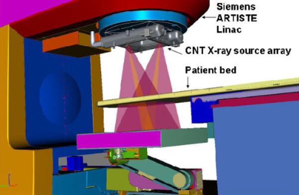
Other applications for tomosynthesis are imaging systems for guiding radiation treatment devices. Three-dimensional imaging for accurate patient positioning and precise dose delivery to the target position are standard in the modern clinical workflow. IGRT allows more precise dose delivery and this enables a treatment prescription using fewer treatment fractions with a higher dose per fraction. A stationary x-ray tube for IGRT has been developed and manufactured in collaboration of XinRay Systems with Siemens Oncology Care Systems [5]. The x-ray tube is designed to be installed on a Siemens ARTISTE radiation treatment system (see Figure 2). Some state of the art treatment machines have either keV on-board imaging systems, installed perpendicular (Varian, Elekta) or opposite to the treatment beam (Siemens kVIEV), or MeV imaging systems (Siemens MVISION) that use the treatment beam for imaging. Other approaches use stereotactic keV x-ray source installations in the floor or the ceiling of the treatment room (Accuray, BrainLAB). The on-board imaging systems allow the acquisition of cone beam CT images before the treatment for patient positioning and single projection images during the treatment for treatment monitoring. The stereotactic systems use two projection images for both positioning and monitoring but lack the capability of acquiring real three-dimensional information. All approaches except MeV imaging suffer from the fact that the images are acquired in planes different from the treatment plane. Ideally, imaging is desired from the beam's eye view. While MeV imaging systems deliver images in the treatment plane, the images suffer from low soft-tissue contrast.
Figure 2.
Stationary CNT tomosynthesis x-ray source mounted to the linac on a Siemens Artiste radio therapy system.
1.2 Field emission based x-ray tubes
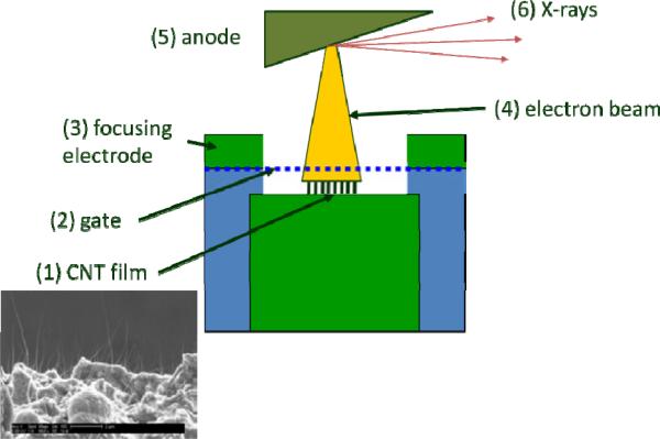
Conventional tubes require a filament to be heated to high temperatures to effect electron emission. In the presented distributed source x-ray tubes, carbon nanotubes (CNTs) are used as electron emitters [6]. Electron beams are generated by field emission, a quantum tunneling process where an electrical field extracts electrons. Figure 3 shows the operating principle. A positive voltage is applied to the gate (2). Because of the short distance (few hundred μm), a high field strength in the order of several V/μm is created and free electrons are generated from the CNT film (1). The electrons are accelerated and focused (3) onto the anode (5). The x-ray generation principle on the anode is the same as for conventional x-ray tubes. The target material is usually tungsten on a carrier material (e.g. copper or molybdenum). Other target materials are also possible.
Figure 3.
Principle CNT field emission source.
Advantages of the field emission electron emitters include: cold cathode: (i) no filament heating required, no heating power in the tube. (ii) Fast inherent emission response time (rise time of the electron emission <1μs), the electron emission is controlled completely by the external field. Switching of the driving voltages can be done very fast and accurately. (iii) They are programmable: each emitter can be driven independently. This can be done in a sequential manner or with several emitters on at the same time (multiplexing). (iv) Custom made designs are possible allowing flexibility in emitter to emitter distance and geometry. 1D or 2D distributed sources have been demonstrated.
2. DISTRIBUTED SOURCE FOR STATIONARY DIGITAL BREAST TOMOSYNTHESIS
2.1 X-ray source design
A tube for sDBT is currently under development in collaboration between UNC Chapel Hill and XinRay Systems. The tube will feature 31 emitters with an angular separation of 1°. The length per pulse will be 250ms with ~30mA anode current and an energy range of 30 to 50kVp. This will allow an exposure of 6.74mAs per projection and a total of 210 mAs for all 31 projections. In Figure 4 an existing UNC demonstration setup is shown and on the right hand side is a CAD model of the new tube design.
Figure 4.
UNC Argus sDBT demonstration setup (left). CAD model of new sDBT x-ray tube currently under development (right).
2.2 Emitter testing results
Figure 5 shows results from recent emitter testing. A test module was installed in a vacuum chamber, the emitters were conditioned and ramped up to the target current. The emitter shown was run for about 40h with a pulse length of 150ms at a cathode current of 30mA. A total of around 7200 pulses were extracted. The driving mode of the emitters was constant current, which means that the gate voltage is adjusted from pulse to pulse to obtain a constant output current. The average current stability in this setup was approx. 0.2%. The gate voltage increased by about 5% over the whole period. After an initial relative fast degradation in the first 10 hours (3%) the change in gate voltage drops down to approx. 0.4% for the last 10 hours. This is a typical behavior attributed to the CNT emitter conditioning. The very stable emission properties lead to expected tube lifetimes of several years even under heavy duty patient load present in mammography screening scenarios.
Figure 5.
7200 pulses, 150ms pulse length and duty cycle of 0.7%. Left: absolute cathode current and applied gate voltage. Right: relative change of current and gate voltage.
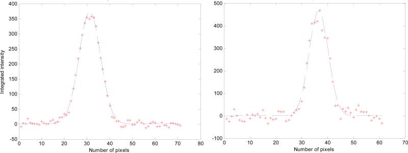
Focal spots have been measured using a pinhole-based method in order to optimize the focusing structure. The focusing structure consists of 3 electrodes: the extraction gate and two active focus electrodes. The potential on each of the focus electrodes can be adjusted to optimize the focal spot size.
Figure 6 shows a typical result from the study. The profiles show a Gaussian shaped intensity distribution with a minimum measured size of 0.9 × 0.6 mm2 (20% intensity). Further optimization of the beam optics is currently ongoing.
Figure 6.
Example of a focal spot measurement at 30kV and 27mA anode current. The measured size is 0.9 × 0.6 mm2 at 20% intensity.
3. DISTRIBUTED SOURCE ARRAY FOR IMAGE GUIDED RADIO THERAPY
3.1 System overview
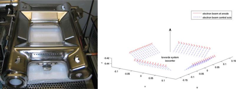
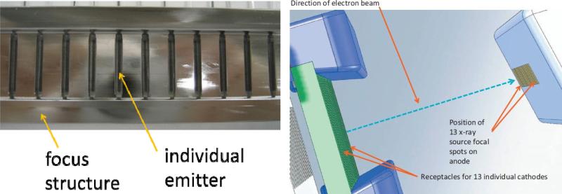
The distributed source array is mounted directly on the gantry of the ARTISTE MV Linac (Figure 2). It uses a square arrangement of 4 × 13 sources that has an opening in the center to allow the passage of the MeV treatment beam (see Figure 7). The same imaging detector is used for the MeV and the keV photon beams. This reduces the system cost relative to the more common two-detector implementations of image-guidance. Tomosynthesis slices are generated in the beam's eye view with good resolution in the treatment plane and the additional depth information. The imaging time is in the range of 5-9s for 52 projections which allows for intra-fractional imaging to verify the patient and target position. The design parameters for the square source are 80-140kVp energy, 20mA anode current per emitter and a pulse length of up to 100ms. The focal spot size is 2mm (FWHM) and the detector readout is ~70ms. The emitters are positioned on a 27cm square with an emitter to emitter distance of 10mm and a total of 13 sources per side of the square. Figure 8 shows one of the 4 emitter arrays with the passive focusing structure and the CNT emitters. The cathode array is placed opposite of an extended anode. The tomosynthesis geometry with a 63cm source-to-image distance results in a 8cm × 8cm field of view (FOV) in the plane of the linac isocenter. The tube design was optimized for compactness in the MeV beam direction for maximum clearance between the patient and the source.
Figure 7.
Square 52 emitter source array for IGRT (left), focal spot positions with electron beam directions in the x-ray tube (right). The focal spot to focal spot distance is 10mm on the anode.
Figure 8.
Image of one of the four cathode arrays including focusing structure (left). The cathode array facing the elongated anode shown in the tube geometry (right).
The tube was assembled, baked and vacuum sealed. Two ion getter pumps provide active pumping and monitoring of the internal vacuum conditions. The tube was HV conditioned and all 52 sources have been conditioned and combined with the electronic control system.
For system integration, a multi-channel electronic control system (ECS) has been developed that can control each individual emitter and provides an Ethernet interface for simple system integration. The ECS regulates the output current to be consistent from pulse to pulse. The rising and falling edges of each pulse can be below 10μs, depending on the application. Pulses can be in the range of 225μs to 250ms. The cathodes are operated at a potential close to ground and the anode is on positive HV. This allows for having the ECS on ground potential without the need to insulate it against anode HV.
3.2. Imaging results
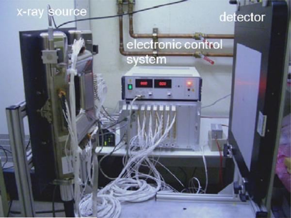
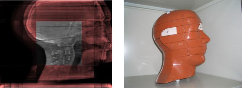
An imaging test setup consisting of the tube, the ECS and a detector was assembled (see Figure 9). The geometry was calibrated using a standard Siemens cone beam calibration phantom. The calibration phantom is an x-ray transparent cylinder made of plexiglass, within which x-ray opaque tungsten ball bearings of two sizes, large and small, are embedded to form a single helix. This is a standard phantom used for calibrating the CBCT imaging systems present in Siemens medical linacs. Calibrating the tomosynthesis system using this calibration phantom is a non-trivial task because the measured pattern is different from each projection. Projection images with different phantoms were acquired. Figure 10 shows a reconstructed tomosynthesis slice from a Rando head phantom (central slice).The regions outside of the central square are not in the FOV. The source parameters were 15mA anode current, 20ms pulse length and 80kVp anode voltage. For the reconstruction, a simultaneous algebraic reconstruction technique (SART) was used that allows the reconstruction from the 52 projections in 6s [7]. The image quality achieved is sufficient for online target verification.
Figure 9.
Imaging setup consisting of the 52 emitter source array, the electronic control system and a detector.
Figure 10.
Reconstructed central tomosynthesis slice from 52 projections (left). Only the central square is in field-of-view. Rando head phantom used in a phantom study (right).
4. HIGH ENERGY TUBE DEVELOPMENT
Many imaging applications require energies above 140kV. Recently we demonstrated that CNT emitters can be operated at 160kV in a sealed vacuum system with excellent current stability. The graphs in Figure 11 show measurements at a mean power of ~120W (the mean power is limited by passive cooling of the test system, active anode cooling is possible which allows for higher mean power) and a peak power per emitter of ~4.8kW (0.5% duty cycle). The pulse length was 225μs. The emitters can withstand HV arcing without noticeable degradation (no change in current after arcing). Initially the degradation rate is higher but after several hours of operation the rate of gate voltage change drops to 0.12 %/h. The total number of pulses in this experiment was ~640000. This makes CNT based distributed sources very attractive for applications beyond tomosynthesis, e.g. stationary CT systems, with expected tube lifetimes comparable to conventional tubes with the advantage of reduced system complexity.
Figure 11.
Total number of pulses 640000, 225μs pulse length. Left: anode voltage 160kV and pressure. The pressure spikes originate from tube arcing. Right: relative cathode current and relative gate voltage. Both graphs show the same time window. HV arcing does not degenerate the field emitters.
5. CONCLUSIONS
Stationary distributed x-ray sources based on field emission cathodes offer unique advantages especially for tomosynthesis applications. The required exposure levels can be achieved with good emitter stability and lifetime. For breast tomosynthesis the stationary distributed sources will allow reduced image acquisition time, improved image quality and simplified system design. The two-dimensional source array will provide additional functionality for IGRT with a fast online image acquisition even while treatment is in progress. Phantom imaging studies have shown sufficient image quality for target verification and tracking. System integration of the presented x-ray tubes will be done in the near future. Field emission cathodes are also demonstrating good stability and lifetime for higher energy applications.
Figure 1.
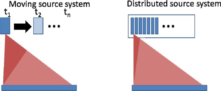
Comparison of moving source system (left) with stationary distributed source system (right). In the moving source the same x-ray tube fires at different times ti, while for the stationary system a different emitter is fired for each position in the stationary x-ray tube at a given time ti.
6. ACKNOWLEDGEMENTS
The stationary breast tomosynthesis project is supported by the National Cancer Institute under grant number 1R01CA134598-01A1. The high energy tube research was supported through a XinRay contract with the Technical Support Working Group (TSWG) with funding from the Department of Homeland Security.
REFERENCES
- 1.Ren B, et al. Design and performance of the prototype full field breast tomosynthesis system with selenium based flat panel detector. Proc. SPIE. 2005;5745:550–561. [Google Scholar]
- 2.Bissonnette M, et al. Digital breast tomosynthesis using an amorphous selenium flat panel detector. Proc. SPIE. 2005;5745:529. [Google Scholar]
- 3.Wu T, et al. Tomographic mammography using a limited number of low-dose cone-beam projection images. Med. Phys. 2003;30(3):365–380. doi: 10.1118/1.1543934. [DOI] [PubMed] [Google Scholar]
- 4.Yang G, et al. Stationary digital breast tomosynthesis system with a multi-beam field emission x-ray source array. Proc. SPIE. 2008;6913:69131A. [Google Scholar]
- 5.Maltz J, et al. Fixed gantry tomosynthesis system for radiation therapy image guidance based on a multiple source x-ray tube with carbon nanotube cathodes. Med. Phys. 2009;36(5):1624–1636. doi: 10.1118/1.3110067. [DOI] [PubMed] [Google Scholar]
- 6.Cheng Y, Zhou O. Electron field emission from carbon nanotubes. C. R. Physique. 2003;4:1021–1033. [Google Scholar]
- 7.Kak AC, Slaney M. Principles of Computerized Tomographic Imaging. Society of Industrial and Applied Mathematics. 2001 [Google Scholar]


