Abstract
The crystal structures of different forms of TiO2 and those of BaTiO3, ZnO, SnO2, WO3, CuO, Fe2O3, Fe3O4, ZrO2 and Al2O3 nanoparticles have been deduced by powder X-ray diffraction. Their optical edges have been obtained by UV-visible diffuse reflectance spectra. The photocatalytic activities of these oxides and also those of SiO2 and SiO2 porous to oxidize iodide ion have been determined and compared. The relationships between the photocatalytic activities of the studied oxides and the illumination time, wavelength of illumination, concentration of iodide ion, airflow rate, photon flux, pH, etc., have been obtained. Use of acetonitrile as medium favors the photogeneration of iodine.
1. Background
Nanoparticles exhibit physical properties distinctively different from that of bulk. They possess a large fraction of surface atoms or ions or molecules in unit volume. The very large surface area provides a huge surface energy. Further, the electronic structures of semiconductor nanocrystals differ from those of bulk materials. Band gap-illumination of semiconductor results in formation of electron-hole pairs; electron in the conduction band (CB) and hole in the valence band (VB) [1]. While most of the electron-hole pairs recombine, some of the charge carriers diffuse to the crystal surface and react with the adsorbed electron donors and acceptors leading to photocatalysis. Here we compare the photocatalytic efficiencies of nanocrystalline semiconductors. Iodide ion is the test substrate taken up for the study. Production of energy bearing chemicals through thermodynamically uphill reactions is the objective of solar energy conversion and storage and iodide ion-oxidation is such a reaction (ΔG° = +51.6 kJ mol-1). In addition, it is well known that degradation of organic molecules involve photogenerated reactive oxygen species (ROS) and the major active oxidizing species is hydroxyl radical [2]. The capacity to photogenerate hydroxyl radical is also taken as a measure of the photocatalytic activity of photocatalyst [3]. More importantly, the photocatalytic mineralization of organics is complicated by the formation of a number of stable intermediates. But the iodide ion oxidation is a simple electron transfer process [4-7]. Further, unlike iodide ion the organic molecules such as phenols and dyes may have chemical affinity to the oxide surface and enter into some sort of bond formation with the oxides. These factors led to the selection of iodide ion as the test substrate for this investigation. The present photocatalytic results on iodide ion oxidation show that some of the nanocrystalline semiconductors are less efficient photocatalysts than insulators such as Al2O3 and SiO2. Recently, we have reported photodegradation of carboxylic acids on Al2O3 and SiO2 nanoparticles [8].
2. Results and Discussion
2.1. Crystal structure
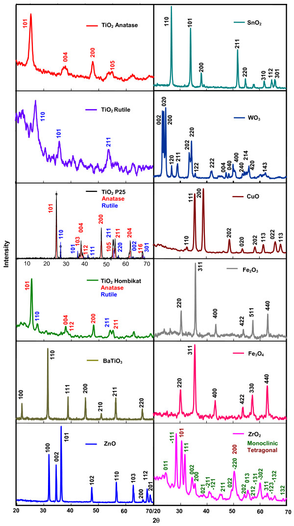
The X-ray diffraction (XRD) pattern of TiO2 anatase, shown in Figure 1, confirms the anatase phase of the sample. The recorded XRD matches with the JCPDS pattern of TiO2 anatase (89-4921, body centered tetragonal, a 3.8101 Å, b 3.8101, c 9.3632, α 90°, β 90°, γ 90°) and the rutile lines (JCPDS 89-4202) are absent. The presence of rutile phase in the rutile TiO2 is evident from the observed XRD of rutile TiO2. While the anatase peaks (JCPDS 89-4921) are not seen, the displayed XRD of the rutile sample matches satisfactorily with the JCPDS pattern of rutile TiO2 (89-4202). The cell parameters are: primitive tetragonal, a 4.627 Å, b 4.627 Å, c 2.9757 Å, α 90°, β 90°, γ 90°. The recorded XRD of TiO2 P25 Degussa confirms the presence of anatase and rutile phases in the sample. The JCPDS patterns of anatase (00-021-1272 (*)) and rutile (01-089-0553 (C)) are observed in the XRD of P25 TiO2. The cell parameters are: anatase: body centered tetragonal, a 3.7852 Å, b 3.7852, c 9.5139, α 90°, β 90°, γ 90° and rutile: primitive tetragonal, a 4.5925 Å, b 4.5925 Å, c 2.9560 Å, α 90°, β 90°, γ 90°. The phase percentages have been obtained from the integrated intensity of the peaks at 2θ value of 25.3° (101-plane) for anatase and 27.4° (110-plane) for rutile. The percentage of anatase is given by A (%) = 100/[1 + 1.265(IR/IA)], where IA and IR are the intensities of anatase and rutile peaks, respectively. The phase composition determined by the XRD method is 81% anatase and 19% rutile, which is in agreement with the literature. The XRD of TiO2 Hombikat shows the presence of anatase and rutile phases in the crystal; peak fitting of the XRD conforms to the combined XRD pattern of TiO2 anatase (JCPDS 89-4921) and rutile (JCPDS 89-4202). The crystal parameters are: anatase: body centered tetragonal, a 3.7792 Å, b 3.7792 Å, c 9.4910 Å, α 90°, β 90°, γ 90°; rutile: primitive tetragonal, a 4.627 Å, b 4.627 Å, c 2.9757 Å, α 90°, β 90°, γ 90°. The percentages of anatase and rutile phases present in the sample, obtained from the XRD data, are 69 and 31, respectively. The powder XRD of BaTiO3 employed confirms its crystal structure as primitive cubic. It is in total agreement with JCPDS 89-2475. The crystal constants are: a 4.0085 Å, b 4.0085 Å, c 4.0085 Å, α 90°, β 90°, γ 90°.
Figure 1.
Powder XRD patterns of nanocrystalline semiconductors.
The recorded diffractogram of ZnO confirms its crystal structure. The peak fitting is highly satisfactory (JCPDS 89-7102) and the deduced crystal parameters are: primitive hexagonal, a 3.2526 Å, b 3.2526 Å, c 5.1888 Å, α 90°, β 90°, γ 120°. The diffraction pattern of SnO2 is in accordance with its structure. It is in complete agreement with that of JCPDS 88-0287. The cell constants are: primitive tetragonal, a 4.7355 Å, b 4.7355 Å, c 3.1703 Å, α 90°, β 90°, γ 90°. The WO3 crystals provide an XRD pattern that belongs to primitive monoclinic system (JCPDS 89-4476). The crystal constants are: a 7.3291 Å, b 7.5006 Å, c 7.6718 Å, α 90°, β 88.18 ± 2.89°, γ 90°. The XRD pattern of CuO matches with JCPDS 89-2529 pattern and confirms the crystal structure as end centered monoclinic with crystal constants as: a 4.6977 Å, b 3.4193 Å, c 5.1285 Å, α 90°, β 81.20 ± 3.76°, γ 90°. The recorded XRD pattern of Fe2O3 shows the oxide as maghemite (γ-Fe2O3). The XRD is in total agreement with JCPDS 39-1346 and the crystals belong to cubic system with unit cell length as 8.3515 Å. The Fe3O4 used is of face centered cubic system. The recorded XRD pattern is in agreement with JCPDS 89-4319. The crystal parameters are: a 8.3381 Å, b 8.3381 Å, c 8.3381 Å, α 90°, β 90°, γ 90°.
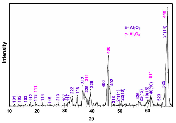
The XRD peaks of zirconia show the oxide as a blend of monoclinic and tetragonal forms. The combined JCPDS patterns of monoclinic ZrO2 (24-1165) and tetragonal ZrO2 (81-1546) match with the observed XRD. The crystal parameters are: primitive monoclinic (baddeleyite), a 5.145 Å, b 5.207 Å, c 5.311 Å, α 90°, β 99.23°, γ 90° and primitive tetragonal, a 3.622 Å, b 3.622 Å, c 5.205 Å, α 90°, β 99.23°, γ 90°. The volume fractions of the tetragonal (χt) and monoclinic (χm) phases are 0.34 and 0.66, respectively. They have been deduced from the integrated peak intensities of the (101)t plane of the tetragonal phase (It) and the (111)m and (-111)m planes of the monoclinic phase (Im) as follows: χt = It (101)/[It (101)+ Im (111)+ Im (-111)] and χm = 1 - χt. The XRD of Al2O3 is displayed in Figure 2. It shows the existence of gamma (γ) and delta (δ) phases. The recorded diffraction pattern matches with the combined JCPDS patterns of γ-Al2O3 (JCPDS 10-0425) and δ-Al2O3 (JCPDS 00-016-0394). The crystal characteristics are: γ-Al2O3: cubic, a 7.9000 Å, b 7.9000 Å, c 7.9000 Å, α 90°, β 90°, γ 90°; δ-Al2O3: tetragonal, a 7.9430 Å, b 7.9430 Å, c 23.5000 Å, α 90°, β 90°, γ 90°. The percentages of γ- and δ-phases are 65.2 and 34.8, respectively.
Figure 2.
Powder XRD pattern of nanocrystalline Al2O3.
The average sizes of the different nanocrystals (D) have been obtained from the half-width of the full maxima (HWFM) of the most intense peaks of the samples using the Scherrer formula D = 0.9λ/βcosθ, where λ is the X-ray wavelength, θ is the Bragg angle and β is the corrected line broadening. The XRD peaks used to calculate the average crystallite sizes are those of 101, 110, 101, 101, 110, 101, 110, 200, 200, 311, 311, -111 and 400 planes of TiO2 anatase, TiO2 rutile, TiO2 P25, TiO2 Hombikat, BaTiO3, ZnO, SnO2, WO3, CuO, Fe2O3, Fe3O4, ZrO2, and Al2O3, respectively. The specific surface areas of the nanoparticles have been deduced using the relationship S = 6/dρ, where S is the specific surface area, d is the mean particle size and ρ is the material density. Table 1 presents the results. The displayed particle sizes and surface areas of amorphous SiO2 are those provided by Sigma Aldrich.
Table 1.
Size (D) and surface area (S) of the oxides with rates of iodide ion-photooxidation*
| Oxide | D (nm) |
S (m2 g-1) |
Iodine-formation (nM s-1) | |
|---|---|---|---|---|
| Water | Acetonitrile | |||
| TiO2 (anatase) | 9 | 165 | 216 | 361 |
| TiO2 P25 (anatase:rutile::81:19) | 23 | 68 | 39 | 257 |
| TiO2 Hombikat (anatase:rutile::69:31) | 18 | 87 | 63 | 232 |
| TiO2 (rutile) | 12 | 123 | 2.5 | 24 |
| BaTiO3 | 41 | 24 | 5.4 | 27 |
| ZnO (wurtzite) | 32 | 33 | 6.9 | 93 |
| SnO2 | 27 | 31 | 2.4 | 21 |
| WO3 | 23 | 39 | 1.6 | 61 |
| CuO | 28 | 33 | 0.4 | 23 |
| Fe2O3 | 39 | 32 | 1.7 | 24 |
| Fe3O4 | 32 | 36 | 0.8 | 21 |
| ZrO2 | 25 | 42 | 1.1 | 20 |
| Al2O3 (γ:δ::65:35) | 11 | 148 | 8.9 | 32 |
| SiO2 | 15 | 160 ± 20 | 12 | 44 |
| SiO2 (porous) | 10 | 640 ± 50 | 6.5 | 27 |
*0.020 g oxide loading, 0.050 M iodide solution (25 mL), 7.8 mL s-1 airflow, 365 nm, 25.2 μEinstein L-1 s-1, 30 min illumination.
2.2. Optical edge
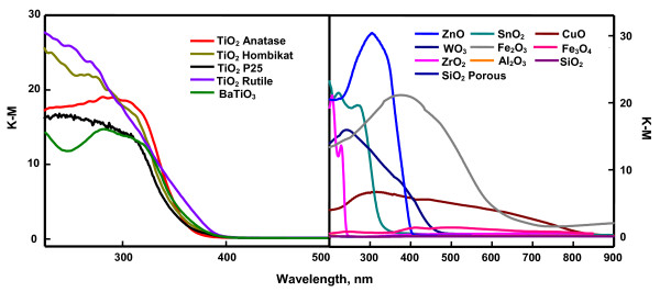
The diffuse reflectance spectra (DRS) of the employed oxides are shown in Figure 3. The reflectance data are presented as F(R) value, obtained by the application of Kubelka-Munk (K-M) algorithm [F(R) = (1 - R2)/2R], where R is the reflectance. The DRS clearly show that SiO2, Al2O3 and ZrO2 do not absorb UVA light. Figure 3 also displays the band gap excitation of TiO2 anatase, TiO2 P25, TiO2 Hombikat, TiO2 rutile, BaTiO3, ZnO and SnO2 under UVA radiation. The DRS further reveals that blue light is capable of effecting band gap excitation of WO3. In addition, the DRS of Fe2O3 displays the commencement of light absorption at about 600 nm itself. Also, the DRS of CuO shows that the oxide is susceptible to photoexcitation by the entire spectrum of visible light. The DRS of Fe3O4 does not show any significant variation in the measured reflectance with visible and UVA light. This is because of its reported band gap of about 0.1 eV [9]. The displayed K-M plots are in total agreement with the expected band gaps of the studied oxides [9]. The band gap of ZrO2 is very wide (about 5 eV) and Al2O3 and SiO2 are insulators and hence do not absorb in the visible and UVA region.
Figure 3.
DRS of the oxides.
2.3. Photocatalytic oxidation of iodide
In aqueous suspension, anatase TiO2 catalyzes iodide ion oxidation more effectively whereas Hombikat TiO2 and TiO2 P25 effectively, Al2O3, SiO2, BaTiO3, and ZnO moderately and ZrO2, rutile TiO2, SnO2, WO3, CuO, Fe2O3, and Fe3O4 feebly under UVA light. The UV-visible spectrum of KI solution illuminated with any of the said oxides reveals iodine formation (λmax 350 nm); the spectra are akin to that of the authentic iodine-iodide solution (not given). Chemical tests also confirm the formation of iodine; the solution turns purple with starch and discharged by thiosulfate. The iodine liberation does not occur in dark. Also, the photogeneration of iodine in absence of the oxides is insignificant (data not presented).
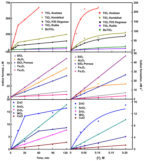
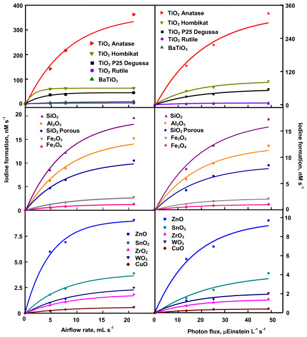
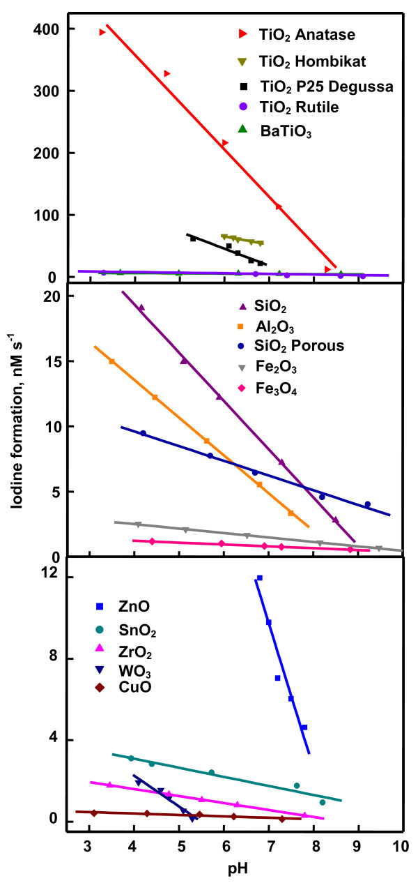
Figure 4 is the time profile of photoformation of iodine. It shows that iodine-generation on TiO2 anatase, TiO2 Hombikat and TiO2 P25 slackens in 15 min whereas that on ZnO and WO3 does so at 30 and 60 min, respectively. The other oxides exhibit sustainable photocatalysis at least up to 2 h of illumination. The slackening of iodine-formation with illumination time is not unknown. Photoformation of iodine on Ag-TiO2 [7], Pt-TiO2 [10], phthalocyanine sensitized TiO2 [11] and immobilized TiO2 [5] or ZnO [5,6] show such behavior. Since the iodine generation on TiO2 anatase, TiO2 Hombikat and TiO2 P25 are not slackened at least up to 15 min and on the other oxides at least up to 30 min, the reaction rates have been obtained by measuring the iodine formed in 15 and 30 min on anatase, Hombikat and P25 TiO2 and the rest of the oxides, respectively. All the nanooxides show sustainable photocatalysis. The recycled oxides without any pre-treatment provide identical results (results not listed). Figure 4 also displays the iodine-formation rate at different concentrations of iodide ion. SnO2, WO3, CuO, Fe2O3, Fe3O4, ZrO2 and SiO2 show linear increase of reaction rate with [I-] indicating first-order kinetics. The other oxides exhibit saturation kinetics revealing Langmuir-Hinshelwood kinetic model [4,7]. The generation of iodine at different airflow rates is displayed in Figure 5. Iodine-formation is enhanced with increased airflow and the variation conforms to Langmuir-Hinshelwood kinetics. Moreover, oxygen is essential for the photoformation of iodine. Iodine is not formed in nitrogen-purged iodide ion solution illuminated with any of the studied oxide (data not listed). The dependence of generation of iodine on the light intensity is also displayed in Figure 5. The photocatalysis lacks linear dependence on photon flux. Less than first power dependence of rates of surface-photocatalyzed reactions on light intensity at high photon flux is known [4,7]. The dependence of photocatalytic iodine generation on the pH of the medium is shown in Figure 6. The pH of the slurry was adjusted by the addition of small volume of NaOH or HCl solution. Except TiO2 rutile and BaTiO3 all other oxides slow down the iodine generation with increase of pH. Rutile TiO2 and BaTiO3 are less sensitive to pH variation. The adsorption of ionic species on the semiconductor depends also on the surface excess charge on the semiconductor crystals. At pH higher than the point of zero charge (PZC), the semiconductor surface is negatively charged resulting in electrostatic repulsion between iodide ion and the semiconductor crystal. Hence, the concentration of iodide ion at the surface and in the double layer is likely to be lesser than that in the bulk of the solution. The adsorption isotherm turns linear leading to a first order kinetics of photocatalysis. The PZC for TiO2, BaTiO3, SnO2, ZnO, WO3, CuO, Fe2O3, Fe3O4, and ZrO2 are 5.8, 9.0, 4.3, 8.8, 0.4, 9.5, 8.6, 6.5 and 6.7, respectively [9]. Examination of Figure 6 reveals, for some oxides at least (TiO2, SnO2, Fe2O3, Fe3O4 and ZrO2), uniform trend in the photocatalysis at pH higher as well as lower than the PZC. A possible explanation is the modification of the PZC values by the ions present in the solution [12,13]. For example, the PZC of TiO2 is reported to change from 6.4 to 4.5 [12]. Hence it is possible that the PZC values of TiO2, SnO2, Fe2O3, Fe3O4 and ZrO2 in the slurry fall outside the range of measured pH. The catalyzed oxidation of iodide ion carried out separately with light of wavelength 254 and 365 nm reveals that UVC light is more effective than UVA light to generate iodine (Table 2). A possible reason for the larger formation of iodine under UVC radiation than UVA radiation is that the generated iodine also absorbs at 365 nm. That is, the liberated iodine may act as an inner filter by absorbing part of the UVA illumination thereby decreasing the intensity of impinging radiation on the nanoparticles. In the case of ZrO2, 254 nm-illumination will bring in band gap excitation. This may lead to the larger iodine-formation. Table 2 also shows that with majority of oxides studied the photogeneration of iodine is more in the immersion reactor than in the tubular reactor. BaTiO3, CuO, Fe3O4, ZrO2 and SiO2 porous are the exceptions. These oxides fail to disperse uniformly throughout the volume of the KI solution (250 mL) in the immersion reactor. It is evident from Table 2 that baring the said five oxides the process is not limited to micro-level.
Figure 4.
Formation of iodine with illumination timea and variation of iodine-formation rate with iodide ion-concentrationb. a0.020 g catalyst loading, 0.050 M KI solution (25 mL), 7.8 mL s-1 airflow, 22.4 mg L-1 dissolved O2, 365 nm, 25.2 μEinstein L-1 s-1; b0.020 g catalyst loading, 25 mL M KI solution, 7.8 mL s-1 airflow, 22.4 mg L-1 dissolved O2, 365 nm, 25.2 μEinstein L-1 s-1.
Figure 5.
Variation of iodine-formation rate with airflow ratea and photon fluxb. a0.020 g catalyst loading, 0.050 M KI solution (25 mL), 365 nm, 25.2 μEinstein L-1 s-1; b0.020 g catalyst loading, 0.050 M KI solution (25 mL), 7.8 mL s-1 airflow, 22.4 mg L-1 dissolved O2, 365 nm.
Figure 6.
Dependence of iodine-formation rate on pH. 0.020 g catalyst loading, 0.050 M KI solution (25 mL), 7.8 mL s-1 airflow, 22.4 mg L-1 dissolved O2, 365 nm, 25.2 μEinstein L-1 s-1.
Table 2.
Iodide-oxidation at different wavelength of illumination and in tubular and immersion reactors*
| Oxide | Iodine-formation (nM s-1) | Iodine-formed (μM) | ||
|---|---|---|---|---|
| 254 nm-illuminationa | 365 nm- illuminationb | Tubular reactorc | Immersion reactord | |
| TiO2 (anatase) | 298 | 170 | 9.7 | 58 |
| TiO2 P25 | 46 | 45 | 1.8 | 20 |
| TiO2 Hombikat | 56 | 49 | 2.8 | 5.4 |
| TiO2 (rutile) | 22 | 2.2 | 0.11 | 0.55 |
| BaTiO3 | 38 | 2.8 | 0.24 | 0.03 |
| ZnO | 25 | 6.3 | 0.31 | 0.90 |
| SnO2 | 21 | 1.8 | 0.11 | 0.28 |
| WO3 | 30 | 0.9 | 0.07 | 0.17 |
| CuO | 24 | 0.3 | 0.02 | 0.01 |
| Fe2O3 | 27 | 1.3 | 0.08 | 0.30 |
| Fe3O4 | 25 | 0.5 | 0.04 | 0.01 |
| ZrO2 | 21 | 0.6 | 0.05 | 0.02 |
| Al2O3 | 34 | 6.8 | 0.40 | 1.1 |
| SiO2 | 43 | 6.8 | 0.55 | 1.8 |
| SiO2 (porous) | 27 | 5.9 | 0.29 | 0.18 |
*0.020 g oxide loading, 0.050 M iodide, 7.8 mL s-1 airflow, 22.4 mg L-1 dissolved O2, 30 min illumination.
a6.2 μEinstein L-1 s-1, 10 mL iodide solution.
b18.4 μEinstein L-1 s-1, 10 mL iodide solution.
c365 nm, 25.2 μEinstein L-1 s-1, 25 mL iodide solution.
d365 nm, 33.9 μEinstein L-1 s-1, 250 mL iodide solution
Comparison of the photocatalytic efficiencies of the nanomaterials reveals TiO2 anatase as the most efficient photocatalyst. Even the benchmark photocatalyst TiO2 P25 Degussa, which is a blend of anatase and rutile, is found to be less effective than the anatase studied. TiO2 rutile shows poor photocatalytic activity. Many semiconductors such as BaTiO3, SnO2, ZnO, WO3, CuO and Fe2O3 fail to display better photocatalytic efficiency than the insulators Al2O3 and SiO2. One of the possible reasons is the unabated rapid recombination of the photogenerated electron-hole pairs in these semiconductors. Another reason could be the large surface area of SiO2. The mechanism of photocatalytic oxidation of iodide ion and also that of iodide ion-photooxidation on Al2O3 and SiO2 surfaces have been discussed elsewhere in detail [4-6,8].
Improving the photocatalytic efficiency, particularly that of generation of energy bearing chemicals via thermodynamically uphill reactions, is of prime concern in solar energy conversion and storage. The listed oxides show improved photoformation of iodine in acetonitrile and Table 1 displays the results. Among the effective semiconductors, on moving from aqueous to acetonitrile medium the photocatalysis by TiO2 anatase improves by about 65% whereas those by TiO2 P25 and Hombikat increases by about 6- and 4-folds, respectively. On switching from aqueous to acetonitrile medium, among moderates catalysis, ZnO improves its efficiency by about 13-fold whereas BaTiO3, Al2O3 and SiO2 could do so only by about 4-fold. Among the feebly active catalyst, the least active CuO and Fe3O4 improve their efficiencies in acetonitrile by about 55 and 25%, respectively. Rutile TiO2 and SnO2 efficiencies go up by 8-fold, whereas that of ZrO2 and Fe2O3 is by about 15%. However, WO3 efficiency is increased by about 35%. General analysis of Table 1 shows that the efficiencies of the less active catalysts are improved many fold on using acetonitrile as medium instead of water. A possible reason for the larger photocatalytic activity in acetonitrile is the absence of hole-capture by hydroxyl ion and water molecule. One of the plausible explanations for the enhanced formation of iodine in acetonitrile on insulator surface may be the efficient transfer of excited electron from the adsorbed iodide ion to the neighboring adsorbed oxygen molecule. In aqueous suspension, adsorption of water molecule and hydroxide ion on the insulator surface may reduce the probability of adjacent adsorption of iodide ion and oxygen molecule. The photocatalytic efficiencies of the nanoparticles are of the order: TiO2 anatase > TiO2 P25 ≈ TiO2 Hombikat > ZnO > WO3 > Al2O3 ≈ SiO2 ≈ SnO2 ≈ BaTiO3 ≈ CuO ≈ Fe2O3 ≈ Fe3O4 ≈ ZrO2. These efficiencies are not in accordance with their band gap energies.
3. Conclusions
The photocatalytic efficiency of anatase TiO2 to generate iodine is much larger than those of TiO2 P25, TiO2 Hombikat, TiO2 rutile, BaTiO3, ZnO, SnO2, WO3, CuO, Fe2O3, Fe3O4, ZrO2, Al2O3 and SiO2 nanoparticles. Some of the studied nanocrystalline semiconductors are less efficient than Al2O3 and SiO2 nanoparticles. The photocatalysis conforms to the Langmuir-Hinshelwood kinetic model. Use of acetonitrile as medium favors the photogeneration of iodine.
4. Experimental
4.1. Materials
TiO2 anatase, TiO2 rutile, ZnO, SnO2, WO3, CuO, Fe2O3, Fe3O4, ZrO2, BaTiO3, Al2O3 and SiO2 nanopowders used were those supplied by Sigma Aldrich. TiO2 Hombikat was supplied by Fluka. TiO2 P25 was a gift from Degussa.
4.2. Characterization
The powder X-ray diffractograms were recorded with a Bruker D8 system using Cu Kα radiation of wavelength 1.5406 Å in a 2θ range of 10-70° at a scan rate of 0.05° s-1 with a tube current of 30 mA at 40 kV. Rich. Siefert model 3000 X-ray diffractrometer was also employed to obtain the diffraction pattern. A PerkinElmer Lambda 35 or Varian-Cary 5E or Shimadzu UV-2450 spectrophotometer was used to record the UV-visible diffuse reflectance spectra (DRS) of the oxides.
4.3. Photoreactors
A photoreactor fitted with eight 8-W mercury lamps of wavelength 365 nm (Sankyo Denki, Japan) and highly polished aluminum reflector was used for the detailed photocatalytic study. The reactor was cooled by fans mounted at the bottom. Borosilicate glass tube of 15-mm inner diameter was employed as the reaction vessel. Immersion type photoreactor with 125-W medium pressure mercury lamp emitting at 365 nm, surrounded by highly polished anodized aluminum reflector, was also used. The reaction vessel was a 500-mL double walled borosilicate immersion well with inlet and outlet for water circulation. Micro photoreactor with 6-W, 254-nm low pressure mercury lamp and 6-W, 365-nm medium pressure mercury lamp was employed to study photocatalysis under UVC and UVA light.
4.4. Photocatalytic study
KI-solutions of required concentrations were prepared afresh and used. The volume of solution employed in multilamp, immersion and micro photoreactors were 25, 250 and 10 mL, respectively. Air was bubbled through the reaction solution using a micro air pump which kept the added nanoparticles under suspension and at constant motion. The airflow rate was determined by soap bubble method, the dissolved oxygen was measured using Elico dissolved oxygen analyzer PE 135 and the light intensity was found out by ferrioxalate actinometry.
Competing interests
The authors declare that they have no competing interests.
Authors' contributions
This work was made by CK's research group. This project was based on the ideas of CK and carried out under his guidance and consultation. PA carried out most of the experimental work and PG was involved in XRD analysis and preparation of the manuscript. All authors read and approved the final manuscript.
Contributor Information
Chockalingam Karunakaran, Email: karunakaranc@rediffmail.com.
Premkumar Anilkumar, Email: anil1179@rediffmail.com.
Paramasivan Gomathisankar, Email: chemgomathi@rediffmail.com.
Acknowledgements
Financial support through research grant no. F.12-64/2003 (SR) by the University Grants Commission (UGC), New Delhi, is thankfully acknowledged. P.A. is grateful to UGC for PF and PG to CSIR for SRF.
References
- Hu X, Li G, Yu JC. Design, fabrication, and modification of nanostructured semiconductor materials for environmental and energy applications. Langmuir. 2010;26:3031–3039. doi: 10.1021/la902142b. [DOI] [PubMed] [Google Scholar]
- Gaya UI, Abdullah AH. Heterogeneous photocatalytic degradation of organic contaminants over titanium dioxide: a review of fundamentals, progress and problems. J Photochem Photobiol C. 2008;9:1–12. doi: 10.1016/j.jphotochemrev.2007.12.003. [DOI] [Google Scholar]
- Xiang O, Yu J, Wong PK. Quantitative characterization of hydroxyl radicals produced by various photocatalysts. J Colloid Interface Sci. 2011;357:163–167. doi: 10.1016/j.jcis.2011.01.093. [DOI] [PubMed] [Google Scholar]
- Karunakaran C, Senthilvelan S, Karuthapandian S, Balaraman K. Photooxidation of iodide ion on some semiconductor and non-semiconductor surfaces. Catal Com. 2004;5:283–290. doi: 10.1016/j.catcom.2004.03.002. [DOI] [Google Scholar]
- Karunakaran C, Anilkumar P. Semiconductor-catalyzed solar photooxidation of iodide ion. J Mol Catal A. 2007;265:153–158. doi: 10.1016/j.molcata.2006.10.016. [DOI] [Google Scholar]
- Karunakaran C, Anilkumar P. Photooxidation of iodide ion on immobilized semiconductor powders. Sol Energy Mater Sol Cells. 2008;92:490–494. doi: 10.1016/j.solmat.2007.11.003. [DOI] [Google Scholar]
- Karunakaran C, Anilkumar P, Gomathisankar P. Kinetics of Ag-TiO2-photocatalyzed iodide ion oxidation. Monatsh Chem. 2010;141:529–537. doi: 10.1007/s00706-010-0288-2. [DOI] [Google Scholar]
- Karunakaran C, Dhanalakshmi R, Manikandan G, Gomathisankar P. Photodegradation of carboxylic acids on Al2O3 and SiO2 nanoparticles. Indian J Chem. 2011. pp. 163–170.
- Xu Y, Schoonen MAA. The absolute energy position of conduction and valence bands of selected semiconducting minerals. Am Mineral. 2000;85:543–556. [Google Scholar]
- Ohno T, Fujihara K, Saito S, Matsumura M. Forwarding reversible phoocatalytic reactions on semiconductor particles using an oil/water boundary. Sol Energy Mater Sol Cells. 1997;45:169–174. doi: 10.1016/S0927-0248(96)00069-4. [DOI] [Google Scholar]
- Hodak J, Quinteros C, Litter MI, Roman ES. Sensitization of TiO2 with phthalocyanines Part 1.-Photooxidations using hydroxoaluminium tricarboxymonoamidephthalocyanine adsorbed on TiO2. J Chem Soc Faraday Trans. 1996;92:5081–5088. doi: 10.1039/ft9969205081. [DOI] [Google Scholar]
- Gimenez J, Aguado MA, Cervera-March S. Photocatalytic reduction of chromium(VI) with titania powders in a flow system. Kinetics and catalyst activity. J Mol Catal A. 1996;105:67–78. doi: 10.1016/1381-1169(95)00148-4. [DOI] [Google Scholar]
- Domenech J, Munoz J. Photocatalytical reduction of Cr(VI) over ZnO powder. Electrochim Acta. 1987;32:1383–1386. doi: 10.1016/0013-4686(87)85071-5. [DOI] [Google Scholar]


