Abstract
In this paper we report and characterize a semi-automatic prostate segmentation method for prostate brachytherapy. Based on anatomical evidence and requirements of the treatment procedure, a warped and tapered ellipsoid was found suitable as the a priori 3D shape of the prostate. By transforming the acquired endorectal transverse images of the prostate into ellipses, the shape fitting problem was cast into a convex problem which can be solved efficiently.
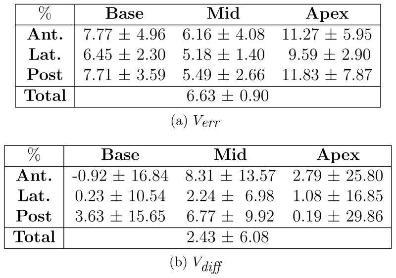
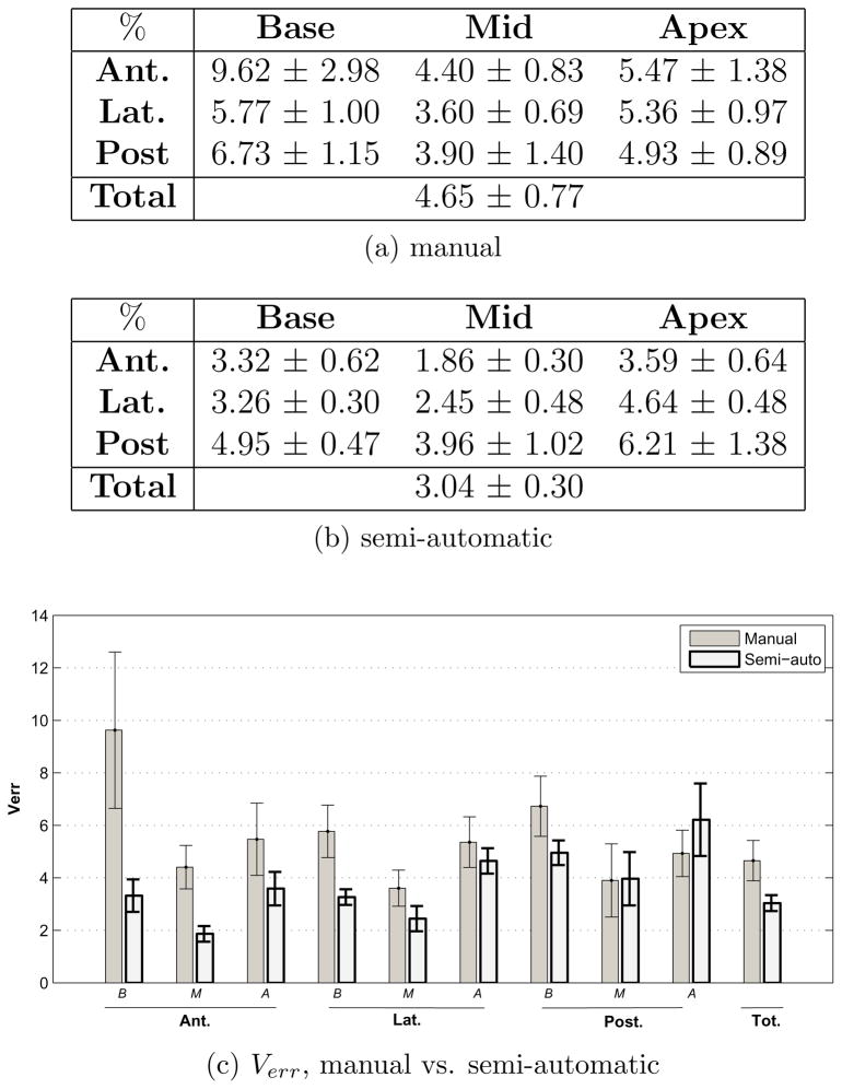
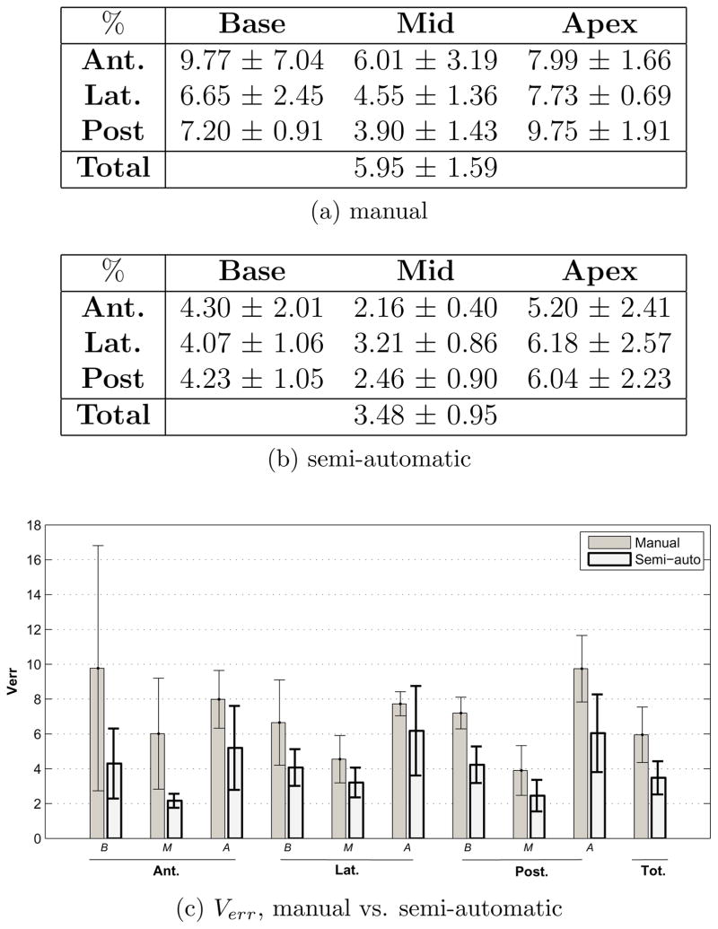
The average whole gland error between volumes created from manual and semi-automatic contours from 21 patients was 6.63±0.9%. For use in brachytherapy treatment planning, the resulting contours were modified, if deemed necessary, by radiation oncologists prior to treatment. The average whole gland volume error between the volumes computed from semi-automatic contours and those computed from modified contours, from 40 patients, was 5.82±4.15%. The amount of bias in the physicians’ delineations when given an initial semi-automatic contour was measured by comparing the volume error between 10 prostate volumes computed from manual contours with those of modified contours. This error was found to be 7.25±0.39% for the whole gland. Automatic contouring reduced subjectivity, as evidenced by a decrease in segmentation inter- and intra-observer variability from 4.65% and 5.95% for manual segmentation to 3.04% and 3.48% for semi-automatic segmentation, respectively. We characterized the performance of the method relative to the reference obtained from manual segmentation by using a novel approach that divides the prostate region into nine sectors. We analyzed each sector independently as the requirements for segmentation accuracy depend on which region of the prostate is considered.
The measured segmentation time is 14±1 seconds with an additional 32±14 seconds for initialization. By assuming 1–3 minutes for modification of the contours, if necessary, a total segmentation time of less than 4 minutes is required, with no additional time required prior to treatment planning. This compares favorably to the 5–15 minute manual segmentation time required for experienced individuals. The method is currently used at the British Columbia Cancer Agency (BCCA) Vancouver Cancer Centre as part of the standard treatment routine in low dose rate prostate brachytherapy and is found to be a fast, consistent and accurate tool for the delineation of the prostate gland in ultrasound images.
Keywords: Prostate interventions, segmentation, trans-rectal ultrasound imaging, prostate brachytherapy
1. Introduction
The young adult prostate has the approximate shape and size of a walnut (Halpern et al., 2002). The superior region of the prostate, or base, encircles the bladder neck, while the inferior region, or apex, of the gland is bounded by the muscles of the pelvic floor. The rectum runs parallel to the posterior aspect of the gland. The prostate is transversally at its largest in the superior mid-gland region and tapers down toward the apex. The normal prostate has average dimensions of 33mm in length (superior-inferior), 24mm in thickness (anterior-posterior) and 41mm in width (left-right). This may vary in different geographical location or due to malignancies such as tumors, benign prostatic hyperplasia, etc.
Low dose rate (LDR) prostate brachytherapy is a common radiation treatment, generally indicated for early stage (intracapsular) prostate cancer with low to intermediate risk features. In this treatment method, 40–150 small radioactive seeds (iodine-125 or palladium-103) are injected through the perineum and permanently implanted into the prostate and periprostatic tissue. The goal is to deliver a tumoricidal dose to the prostate plus the planning margin (comprising the planning target volume, or PTV) while maintaining a low and tolerable dose to radiosensitive regions such as the urethra and rectum.
Prior to treatment planning, a pre-operative trans-rectal volume study is carried out in which a series of 9–14 parallel trans-rectal ultrasound (TRUS) images of the prostate are taken with a spacing of 5mm. These images are manually segmented by a radiation oncologist, who also adds the planning margins from which a 3D PTV is created. A medical physicist subsequently generates a treatment plan that attempts to conform the prescription dose to the volume. Implementation of the treatment plan is carried out 3–5 weeks later.
Manual segmentation of the TRUS images is tedious and demonstrably subjective, depending on the experience, skill, and technique of the contourer. This is particularly evident in the base and apical regions of the gland, where the prostate boundary blends into the surrounding anatomy on TRUS images, becoming more ambiguous and difficult to delineate. Consequently, there is substantial inter-observer variation in the contours for a given patient in these regions.
For an algorithm to improve the efficiency and consistency of the brachytherapy treatment, it needs to satisfy the following important requirements. First, it should be able to produce contours that are not distinguishable from those generated by medical practitioners. Second, it should produce contours that are amenable to the design of uncomplicated treatment plans. Third, it should not require considerable changes to the conventional clinical procedure. Moreover, a fast and automatic solution to manual contouring would greatly facilitate intra-operative planning, where additional and significant gains in treatment quality are likely to be realized (Nag et al., 2001).
In the proposed method, the boundary of the prostate in TRUS images is delineated based on prior knowledge of the shape of the gland resulting in smooth, symmetric and less user dependent contours. The 3D geometric model of the prostate is created based on the assumption that the prostate has a tapered ellipsoidal shape and is slightly warped posteriorly due to the presence of the TRUS probe. Using an a-priori shape - in this case, a tapered, warped ellipsoid- aids segmentation in the less visible base and apex of the gland. Manual initialization of the algorithm makes use of the physician’s experience. The simplicity of the algorithm and the formulation of the most intensive part of the computation as a convex problem results in a fast, close to real-time, repeatable, segmentation method.
Symmetry and smoothness are two other desired features which greatly aid treatment planning. The use of symmetric contours with respect to the sagittal plane for treatment planning is an accepted practice. Symmetric contours lead to simple treatment plans that are also simple to change to insure adequate dose coverage, should the shape, size and position of the prostate change significantly with respect to the volume study. A population study of biochemical and survival outcomes on a total of 1006 consecutive prostate brachytherapy interventions (July 1998 – October 2003) performed at the BC Cancer Agency, the institution where we collected the patient data, shows excellent oncologic outcomes for men with favorable-risk disease, with very low rates of biochemical or metastatic recurrence (Morris et al., 2009).
The paper is arranged as follows: Section 2 is a brief review of recent work on medical image segmentation, mainly focusing on prostate segmentation. Section 3 defines the problem to be solved and assumptions used. In Section 4 the algorithm is introduced along with the measures and methods used for evaluating this algorithm. Evaluation results can be seen in Section 5 and finally the conclusion is presented in Section 6.
2. A review of previous work
Various prostate segmentation methods have been proposed in recent years (Noble and Boukerroui, 2006). These can be classified into those which solely rely on image data, and those which incorporate prior information about the expected shape of the prostate. The advantage of not constraining the solution to certain geometrical classes may result in more robust segmentation of irregular prostate shapes and some prostate surface abnormal deformations that may be caused by cancer. Examples of image-based segmentation methods used in the literature are contrast enhancement, image smoothing and Canny’s edge detector (Pathak et al., 2000), multi-resolution discrete wavelet pyramids for coarse-to-fine segmentation (Boukerroui et al., 2003) and the use of phase symmetry for outlining dominant edges and linking edge segments to create a final contour (Zaim, 2008).
However, the disadvantage of methods that rely solely on image information is that they are more sensitive to factors such as image quality and noise, and generally require more effort to achieve reasonable results. Because they do not use prior shape data, the majority of the proposed general segmentation methods do not work for ultrasound images of the prostate. Deformable models such as active contour models (ACM) and snake models have been widely used for medical image segmentation. They are curves or surfaces in which the deformation (e.g. with the means of Gabor filters) is guided by internal forces (e.g. the constraint of the curve being smooth) and external forces (e.g. edges in the image). Because they can not tolerate the large amount of noise in ultrasound images very well, for such methods to work, additional constraints must be imposted, e.g., the deformation must be limited by an a-priori shape, or alternatively, significant user interaction must be used (Noble and Boukerroui, 2006). Active shape models (ASM) (Cootes et al., 1995) use shape models that deform within some constraints. These constraints and the initial shape model are derived, statistically, from a training set. (Ecabert et al., 2008; Hodge et al., 2006; Huang and Metaxas, 2008; Jendoubi et al., 2004; Ladak et al., 2000; Nanayakkara et al., 2006; Nascimento and Marques, 2008; Pluempitiwiriyawej et al., 2005; Shen et al., 2003; Thevenaz and Unser, 2008; Yezzi et al., 1997; Zhan and Shen, 2006; Zhan et al., 2007).
The use of ellipses, ellipsoids, superellipses and other similar shapes has been a relatively attractive approach for prostate segmentation as most prostates conform well to these representations, and the reduced parameter space results in fast segmentation algorithms. In Kachouie et al. (2006) the velocity of an evolving ellipse initially placed on the center of the prostate is guided by the first and second moments of the Gaussian probability density function fitted to the image histogram. However, further work is said to be needed for robustness to poorer images. Gong et al. (2004) have used deformable superellipses; ellipses that can be deformed by adjusting their aspect ratio, squareness, tapering and bending. Their extensive comparison of manual and computer-generated contours on 125 prostate ultrasound images resulted in a mean error of less than 2 mm between computer generated and manual contours. The segmentation duration was reported to be less than 5 seconds for each 256 × 256 image on a Pentium 4 PC running at 2 GHz. However, this method only generates 2D contours. Penna et al. (2007) create a 3D model of the prostate using a new class of surfaces: Fourier Ellipsoids. This method has the advantage of being able to handle more complex shapes. However, in vivo quantitative validation has not yet been carried out.
In Badiei et al. (2006) an ellipsoidal volume is generated. The method is based on fitting ellipses and ellipsoids with the aid of initial points defined by the user and the Interacting Multiple Model Probabilistic Data Association (IMMPDA) (Abolmaesumi and Sirouspour, 2004) edge detection technique. It has the benefit of being fast, owing to solving a convex problem, but often results in relatively large false positive regions mainly in the anterolateral and inferior regions of the gland. This is due to the tapering of most prostates both in the 2D transverse plane and in the 3D volume along the main axis from the base to the apex. In Mahdavi and Salcudean (2008) we introduce 2D tapering which is later extended to 3D in Mahdavi et al. (2009). The complete approach, together with a more extensive evaluation, are provided in this paper.
Amongst the many proposed methods for segmentation of the prostate in ultrasound images, only a small number offer 3D segmentation of the gland (Hodge et al., 2006; Hu et al., 2003; Penna et al., 2007; Tutar et al., 2006; Zhan and Shen, 2006). The need for using 3D models as opposed to 2D is specifically seen when the quality drops in some image slices, specially the base and apex. With the use of a 3D model and the higher quality mid-region images, contours can be generated for the lower quality base and apical images based on the shape of the mid-gland. Additionally, surface smoothness from one image to the other is more easily maintained. The method proposed in Penna et al. (2007) requires 90 seconds to create the prostate surface model and generate the solid models necessary for HIFU therapy planning. Of this duration, only 10 seconds are required to model the surface. However, manual tracing of approximately 5 transverse and 3 sagittal images of the prostate is needed to initialize this algorithm, which, as reported, requires another 1.5 minutes and introduces operator variability that has not been quantified. In Tutar et al. (2006), 3D semi-automatic segmentation is based on fitting the best surface to a set of images under shape constraints. These constraints are derived by modeling the shape of the prostate using spherical harmonics. A measure of percent volume overlap (the intersection divided by the union of two volumes) between automatic and manual (average of three observers’ manual contours) of 83.5 % is reported on a data set of 30 patients, while the inter-observer variability is 82.8 %. However, this method also requires the user to manually segment the mid-gland axial and sagittal contours for initialization. After initialization, the 3D prostate shape is identified in 1–4 minutes, of which the authors report initialization times of approximately one minute. In Zhan and Shen (2006) the use of a deformable model based on statistical matching of both texture and shape on 3D TRUS images (256 × 256 × 176 volume size, 0.312 mm/voxel) is used. They report a mean overlap volume error of 4.16 % compared to manual segmentation on six patients and a segmentation time of 3 minutes. Since their method is applied to 3D TRUS images, how it will fare relative to a conventional prostate volume acquired with a brachytherapy stepper, where the slices are at 5mm intervals (resulting in 8–12 images per case), is not discussed in the paper. A 2D segmentation method based on active shape models is described in Hodge et al. (2006). This method was extended to 3D by using a rotational-based slicing method which results in an average mean absolute distance and maximum distance of 1.09±0.49 mm and 7.27±2.32 mm between manual and automatic contours (on 36 patient data sets). The gold standard was created by averaging three repeated manual delineations of three trained graduate students. The average run time is reported 6.9±2.1 minutes. This includes the average time needed for manual editing of the 2D images. Manual editing is allowed after each 2D image is segmented (reported to be needed in 26.3 % of the 2D images in each case), after which the modified points are then clamped and the model is re-deformed. The performance of the method without manual editing, and the inter and intra-observer variability of the algorithm have not been reported.
Relative to the above mentioned 3D prostate segmentation methods, our method requires less extensive user interaction, has a smaller total segmentation time, including initialization, and has a substantially faster user-independent segmentation time, making it a suitable candidate for later extensions to real-time dosimetry. Furthermore, we provide a complete method characterization, including segmentation error volumes and intra and inter-observer variability, as provided in Penna et al. (2007).
3. Problem Statement and Assumptions
Given a series of 2D trans-rectal transverse B-mode ultrasound images of the prostate (B&K Pro-Focus System B-Series machine with the MFI Biplane Transducer, image size 640 × 480 pixel, 0.155mm 2D image resolution, 5mm image spacing), from the base to the apex, the goal is to generate a 3D volume of the gland in a real (or close to real) time, preferably using the least user interaction. For ease of treatment planning and execution, the prostate brachytherapy procedure in the BCCA Vancouver Cancer Centre, prefers symmetric and smooth 3D prostate volumes. Also, speed is important for the future use of this algorithm intra-operatively. It is assumed that the prostate is positioned in the TRUS images such that symmetry is maintained with respect to the mid-sagittal plane. This is usually met since the current treatment planning procedure requires such a condition. If such a condition is not met, an initial rotation and translation can be easily applied to the images.
4. Methodology
TRUS images of the prostate show posterior warping of the gland due to the presence of the TRUS probe. Additionally, tapering is often seen both transversally, toward the anterior aspect of the gland (creating a pointed appearance), and axially, with the gland narrowing toward the apex. Our method is based on the assumption of separability between the probe-induced warping, the tapering, and ellipsoidal fit, so that each can be handled independently. In doing so, the fitting and hence, the segmentation problem, is simplified into the convex problem of fitting an ellipsoid to the preprocessed data. Fig. 1 illustrates the main steps of the segmentation algorithm. Details of each step are presented below.
Figure 1.
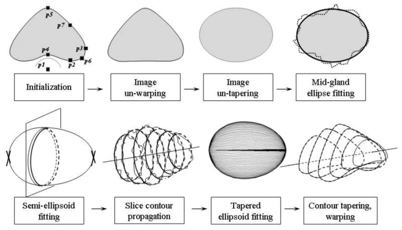
The main steps of the segmentation algorithm.
4.1. Algorithm
4.1.1. Initialization
A prostate volume study used for brachytherapy treatment planning consists of a set of transversal prostate images. Selection of the mid-gland, apex, and base images is the first step in the semi-automatic segmentation algorithm. The mid-gland image is where the initial 2D segmentation will be carried out. It contains the largest and most visible section of the gland. The base and apex are the extreme superior and inferior images of the prostate, respectively. They are not always visible in TRUS images, and will not be used in the algorithm. Their contours will be defined by projection of the final 3D shape on the respective planes. However, the depth of the base and apex images is important in order to extend the segmentation from 2D, on the mid-gland, to 3D. The term ‘slices’, hereafter, will refer to the images starting from image base + 1 to image apex − 1.
On the mid-gland image, the user selects six boundary points which, in addition to p1 - the TRUS probe center, initiate the algorithm. These boundary points are: p2-lowest posterior lateral, p3-extreme right, p4-mid-posterior, p5-mid-anterior, p6- intersection of the mid-perpendicular line between p2 and p3 with the boundary, and p7- intersection of the mid-perpendicular line between p3 and p5 with the boundary (Fig. 2a). Points p3, p4, and p5 are primarily determined by the size of the prostate. Points p1, p2, p4 are used to calculate the amount of warping. Points p6 and p7 have the main contribution in determining the amount of tapering. The aim is to extract the most information from the image while keeping the variability of the point selection low by directing the user to specific regions; either to extremes (e.g. points p3, p4, and p5) or by guiding lines (points p6 and p7). These points along with their symmetric reflections across the medial line will be referred to as the ‘initial points’.
Figure 2.
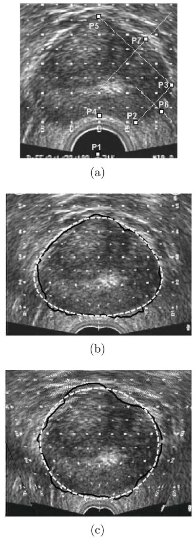
a) Initialization points, b) Image un-warping, IMMPDA edge detection and tapered ellipse fitting (dashed), c) Image un-tapering, IMMPDA edge detection and ellipse fitting (dashed).
4.1.2. Image un-warping
Based on the initial points, the posterior region of the mid-gland image is un-warped to reduce the deformation caused by the TRUS probe using Eq.1 below. In this equation r is the current distance of an image pixel on a radial line starting from the probe center with angle φ (φ = 90° being the medial line) and rnew is the distance of the re-located pixel. In this sinusoidal Gaussian function, the maximum deformation is achieved when φ = 90° and reduces as r increases.
| (1) |
σ is a variable which represents the amount of radial stretch and is calculated by solving Eq. 1 for φ = 90° to obtain:
| (2) |
In this angle, r is set as the distance between p1 and p4 and rnew as the distance between p1 and the reflection of p4 about a horizontal line passing through p2. If rnew > r no un-warping is required.
Eq.1 is also used to un-warp the initial points. Assuming that the presence of the TRUS probe causes uniform deformation along the prostate, all the other TRUS images are also un-warped. Therefore, the effect of the TRUS probe on the gland is largely removed.
4.1.3. Image un-tapering and mid-gland ellipse fitting
The un-warped initial points are used to fit an initial tapered ellipse on the now un-warped mid-gland slice (Fig. 2b). The tapered ellipse parameters P = (x0, y0, ax, ay, t1) are found by solving the following problem using the recursive Levenberg-Marquardt algorithm (Bazaraa et al., 2006):
| (3) |
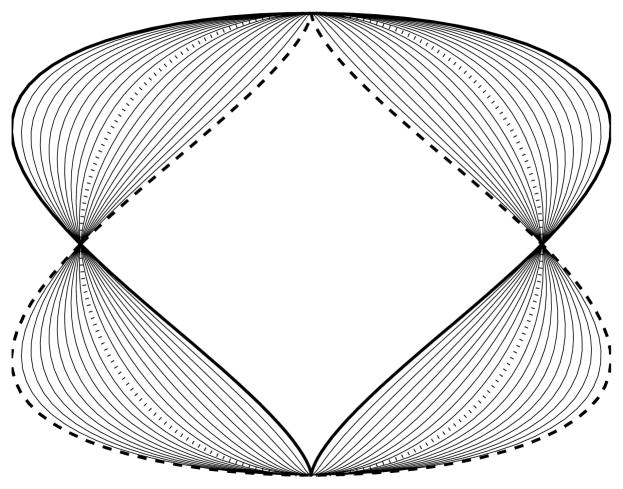
with ax and ay being the radii along the axes, −1 ≤ t1 ≤ 1 the tapering parameter and [x0, y0] the center of the shape. [xi, yi], i = 1 … N, are the coordinates of the boundary points with N being the number of initial points as previously defined. Fig. 3 shows the effect of changing the tapering value, t, in a tapered ellipse from −1 (thick dashed line) to +1 (thick line).
Figure 3.
The effect of changing the tapering parameter from −1 (thick dashed line) to 1 (solid line). A tapering value of zero corresponds to an ellipse (dotted line).
Throughout this algorithm, 2D segmentation is carried out with the aid of the IMMPDA edge detector (Abolmaesumi and Sirouspour, 2004). In this edge detector, the evolution of the radius from an arbitrary seed point inside the contour to the contour edge is modeled as a dynamic system in the radius angle. Multiple models can be incorporated in the dynamic system to accommodate abrupt changes in the edge. Two constant velocity models (Eq. 4) have been used in our approach.
| (4) |
where j = 1, 2 is the number of trajectory models used to describe the boundary, are the system states at the kth radius in which dj(k) is the distance of the prostate boundary from the arbitrary seed point inside the prostate and dθj (k) is its derivative with respect to angle θ. Vj(k) is the process noise vector with covariance Qj(k). Zj(k) is the process output (measured boundary location) and ωj(k) is the measurement noise with covariance Rj(k). The two models used in our implementation have the following process noise vector and measurement noise covariances:
where the numerical values have been obtained by trial and error in prior work (Badiei et al., 2006) and have not been adjusted for any of the patient data they were used in. Each trajectory model is associated with a Kalman filter. The output of these filters is combined with a probabilistic data association filter for more accurate contour extraction. Since no numerical optimization technique is used in the IMMPDA method, it is fast enough to be used repetitively within a segmentation algorithm. Meanwhile, the interacting multiple model (IMM) estimator increases its accuracy and robustness when noise is present in the images. For further details please refer to (Abolmaesumi and Sirouspour, 2004)
The initial tapered ellipse fitted to the initial points is used to guide the IMMPDA edge detector by setting limits on how far from this contour the edge detector can search. These limits prevent the edge detection from drifting away from the prostate boundary in regions with low image contrast. The resulting edge points are once again fed to the Levenberg-Marquardt algorithm to obtain an improved fit of the tapered ellipse. The tapering value of this contour, t1, is used to un-taper the ultrasound images. We assume that the prostate is most tapered at the mid-gland and the tapering linearly reduces to zero superiorly and inferiorly. Using the negative of the tapering value for each slice, all images along with the initial points on the mid-gland slice are un-tapered. The result of this step are transverse images in which the prostate has an elliptical shape.
An ellipse is fitted to the un-warped and un-tapered initial points. This can be done in many ways; we use the simple and fast generalized eigenvector solution of Varah (1996). The ellipse guides the IMMPDA edge detector and to the extracted edges, a second ellipse is fitted on the mid-gland slice (Fig. 2c).
4.1.4. Semi-ellipsoid fitting for slice contour propagation
An IMMPDA edge detection and second ellipse fitting similar to that applied to the mid-gland slice is carried out on the rest of the slices. However, since there are no user defined points on these images, the initial ellipses are created by fitting two semi-ellipsoids; one that extends superiorly toward the base, and another inferiorly toward the apex (see Fig. 1). Each is fitted to the union of the data points on the mid-gland contour and the point on the intersection of the axial line passing through the center of the mid-gland contour with the respective base − 1, or apex + 1 slice. This is again solved as a generalized eigenvector problem. Two semi-ellipsoids were found to give a better initial approximation than a single ellipsoid because the prostate tapers more rapidly toward the apex.
The intersections of these two semi-ellipsoids with each of the slices are used to guide the subsequent IMMPDA edge detection on each slice. A line is fitted to the centers of the resulting 2D contours. This line represents the main axis of the prostate and will be later used for re-aligning the final 2D contours.
4.1.5. Tapered ellipsoid fitting
At this stage, 2D contours have been generated from all un-warped and un-tapered images. Yet there is no guarantee that smoothness and continuity is maintained from one contour to the next, in the direction of the TRUS probe. Hence, a tapered ellipsoid with an elliptical cross-section and tapering along its main axis is fitted to these contours. Similarly to the 2D tapered ellipse fitting, P = (x0, y0, z0, ax, ay, az, t2, t3) is obtained by solving the following problem using the Levenberg-Marquardt algorithm:
| (5) |
where ax, ay, az are the radii along the axes, [x0, y0, z0] is the position of the center of the volume and t2 and t3 are the respective x and y tapering values in the direction of the TRUS probe. [xi, yi, zi], i = 1 … M are the coordinates of the M boundary points generated by segmenting all image slices.
The fitting of this 3D shape to the boundary points is no longer a convex problem and is the most time consuming part of the algorithm. Suitable selection of the initial parameters, can greatly reduce the search period and prevent the optimization algorithm from converging to local minima. To aid the optimization algorithm, the center of the 3D shape, [x0, y0, z0], and the axes, ax, ay, az, are determined by first fitting an ellipsoid to the data cloud consisting of the ellipse contours of all slices. Since this is a generalized eigenvalue problem, the one and only minimum is found almost instantly. The six derived parameters are used along with two tapering parameters, t2 and t3 initially set to zero to define an ellipsoid, as starting values for the optimization algorithm (Eq.5).
4.1.6. Contour tapering and warping
We have assumed that the prostate is parallel to the TRUS probe and not rotated about its main axis. This reasonable assumption simplifies the fitting problem since introducing three additional rotation parameters into the optimization algorithm will increase both the running time and the possibility of the algorithm converging to local minima. To take account of the possibility that the prostate may be slightly pitched or yawed, the best line fitted to the centers of the extracted 2D contours of all images before 3D shape fitting, is used as the actual axis of the final 3D shape. After slicing the 3D tapered ellipsoid at the corresponding image depths, the centers of the final 2D contours are repositioned to align with this axis.
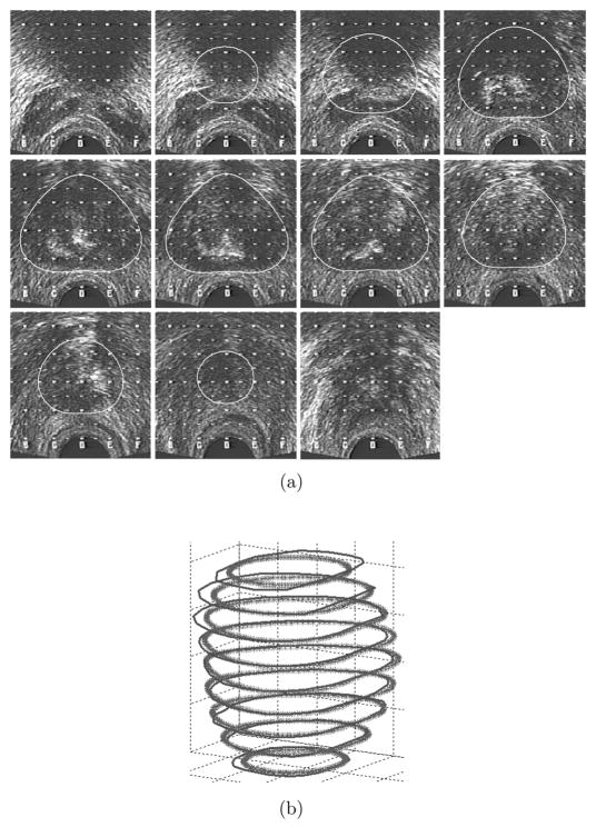
Finally, the repositioned contours are tapered and warped to match the original images (Fig. 4a, 4b). The negative of the same tapering values initially used to un-taper the images is used to taper the contours. However, to ensure that the posterior aspect of the contours do not overlap with the rectum, the warping parameter may need to be modified. When the mid-posterior point on the final contour is lower than the initial posterior point selected by the user, the σ is re-calculated using (2) but with r and rnew respectively set to the distance between p1 and p4 and the distance between p1 and the mid-posterior point on the final mid-gland contour. This change in s is only made if r > rnew, otherwise, the previous value of σ is used.
Figure 4.
a) Final contours on the TRUS B-mode images, b) Final semi-automatic 3D volume (thick lines) compared to manual segmentation (thin lines).
4.2. Evaluation
The presented semi-automatic prostate segmentation algorithm is currently being used by all the radiation oncologists who practice prostate brachytherapy at the Vancouver Cancer Centre, BCCA. Prior to treatment planning, initial delineations of the prostate, hereinafter called ‘pre-modified semi-automatic’ contours, are approved and modified, if deemed necessary, by the radiation oncologist in charge of the patient treatment. We will call these approved contours, whether modified or not, ‘post-modified semi-automatic’ contours. The post-modified semi-automatic contours are used by medical physicists to generate a treatment plan, which in turn is again checked by the radiation oncologist before the actual implant takes place. Thus, while our semi-automated prostate segmentation is used to provide initial contours, these are not used for treatment without the treating radiation oncologists having the final say.
Modifications applied to the contours are not always due to segmentation errors, but are mainly required for brachytherapy treatment planning purposes, to ensure that the treatment plans created on these contours are robust and implantable. This is also observed in manual segmentation where the physician may not necessarily follow the prostate boundary e.g. to avoid needle interference with the pelvic bone or manage dose distribution in a certain region.
To evaluate this algorithm we have carried out two sets of studies: evaluation of the accuracy of the algorithm, and evaluation of the repeatability of the algorithm. We start by comparing the semi-automatic contours before and after modification to indicate to what extent and in which regions the performance of the algorithm was not satisfying for brachytherapy treatment planning. In order to understand how biased the physicians’ modifications are by the initial semi-automatic contours, we compare the post-modified semi-automatic results with that of manual. In order to evaluate our method based on a commonly used approach in the literature, we compare the pre-modified semi-automatic results with that of manual, generally used as the reference in the literature. In the next step we measure inter- and intra-observer variability of both manual and semi-automatic segmentation. A comparison of these two provides a judgment on the repeatability of the algorithm. The acceptable range for the segmentation error is provided by the intra- and inter-observer variability of manual contouring.
The term ‘reference’, used throughout this work refers to the prostate geometric shape relative to which the comparison is carried out. Depending on the study, this can be manual segmentation results, post-modified segmentation results, etc. The term ‘case’ refers to a set of patient images. An ‘observer’ is an individual carrying out segmentation. All observers who perform contouring in this paper have adequate knowledge in manual and/or semi-automatic segmentation and include an expert radiation oncologist, a radiation therapist and a graduate student with significant training in ultrasound prostate segmentation.
The comparison measures used are:
Mean Absolute Distance, MAD: the average absolute radial distance between contours CA and CB, in a slice.
Maximum Distance, MAXD: the maximum absolute radial distance between contours CA and CB in a slice.
Since the boundary of the prostate in the mid-gland slice is visible enough for manual segmentation, these two measures are calculated for this slice only.
Percent volume difference (%), V diff: the difference between the volumes of two delineated prostates defined as:
| (6) |
in which ref in this equation is the reference and V denotes the volume.
Percent volume error (%), V err: the absolute volume of the non over-lapping region between two delineated prostates defined as:
| (7) |
V diff and V err provide measures of size similarity and shape similarity, respectively. They are either calculated for the entire prostate, or for each of the nine sectors of the gland (Fig. 5). The nine sectors are created by first subdividing the prostate into posterior, anterior, and two lateral sectors, the latter of which are considered as a single region. The axis of division is the axis of the reference shape. These regions are then partitioned according to whether they are in the base, mid-gland or apex (respectively 0.3, 0.4, 0.3 of the length of the base-apex axis), forming a total of nine sectors for the purposes of analysis.
Figure 5.
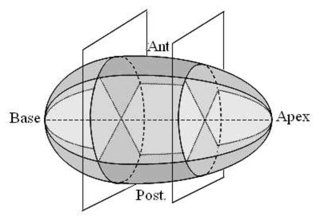
Division of the gland into nine sectors.
This subdivision scheme is clinically motivated by the different consequences of segmentation errors with respect to treatment planning in these regions. For example, because the posterior aspect of the prostate is adjacent to the rectum, overestimating the boundary there can result in high doses to the radiosensitive rectal wall and subsequently higher rates of rectal morbidity. This analysis therefore aims to consider contouring performance in the context of treatment.
4.2.1. Accuracy
This consists of a comparison between 3D shapes generated from: (i) pre-modified semi-automatic contours and post-modified semi-automatic contours (the reference), (ii) manually segmented contours (the reference) and post-modified semi-automatic contours, (iii) manually segmented contours (the reference) and pre-modified semi-automatic contours.
Comparison between pre- and post-modified contours can give a measure of how satisfied the physicians are with the results of the algorithm and which regions of the prostate need the most modifications. It can indicate the degree of which semi-automatic contouring alone is successful in providing reasonable prostate contours for treatment planning. In this analysis, a total of 40 cases were semi-automatically segmented by various radiation therapists and then modified by radiation oncologists.
Modifications of the physicians to the semi-automatic contours may be biased by the initially given contours. To measure this bias, we compare manually created contours for 10 prostate image sets with post-modified semi-automatic contours, generated by three observers (one expert and two trained by experts) for the same image sets.
Finally, to include a commonly used method of evaluation reported in the literature, a comparison between prostate shapes generated by the semi-automatic algorithm and by manual segmentation, is also carried out. For this purpose, 21 cases were manually segmented by an expert and two individuals trained by an expert and the average of their contours were compared to semi-automatic segmentations of an observer experienced with the algorithm and blind to the manual contours.
4.2.2. Repeatability
This analysis is performed to evaluate the consistency of the contours across different observers and at different times. It consists of comparison between (i) manual contours generated by different observers vs. the ‘average’ manual contour (the reference) and semi-automatic contours generated by different observers vs. the ‘average’ semi-automatic contour (the reference) and (ii) initial semi-automatic (the reference) vs. repeated semi-automatic and initial manual (the reference) vs. repeated manual contours. For this aim, 10 cases were segmented by different observers once manually and once using the algorithm. Five of these cases were repeatedly segmented both manually and using the algorithm after approximately two weeks. All observers were blind to each others contours, their previous segmentations and patient data. (i) gives a measure of inter-observer variability and in (ii) intra-observer variability is quantified. Manual intra-observer and inter-observer variability also provide means of evaluating the accuracy obtained in the previous analysis.
The ‘average’ manual/semi-automatic contours are the average of the manually/semi-automatically delineated gland, by each observer, on each slice.
5. Results
The results of each evaluation study are as follows:
5.1. Accuracy
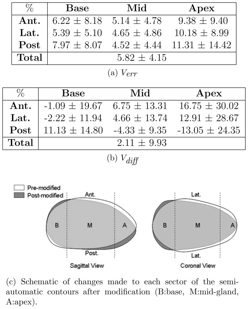
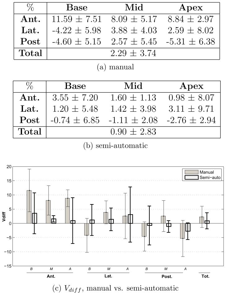
The mean and standard deviation of the absolute percent volume error and volume difference between pre-modified (segmentation algorithm’s results) and post-modified contours (expert approved contours used for treatment planning) are calculated for the nine sectors and the total gland and presented in Fig. 6a and 6b. Whether these errors are clinically considered large or not will be determined in the following section. Based on these two tables, a schematic of the modifications made in each sector is drawn in Fig. 6c. From the sagittal view it appears that on average, the algorithm over-estimates the mid-anterior, anterior-apex and posterior-base and under-estimates anterior-base, mid-posterior and posterior-apex. This may be a result of the algorithm not entirely capturing the tilt of the prostate. The coronal view shows that laterally, the size of the base is increased and the mid and apex are reduced in size after modifications.
Figure 6.
Comparison of pre- and post-modified semi-automatic prostate sectors.
The average MAD and MAXD between pre- and post-modified semi-automatic contours for the 40 cases on the mid-gland slice is 0.71±0.75 mm and 2.00±1.87 mm with 11 out of the 40 mid-gland contours requiring absolutely no modifications.
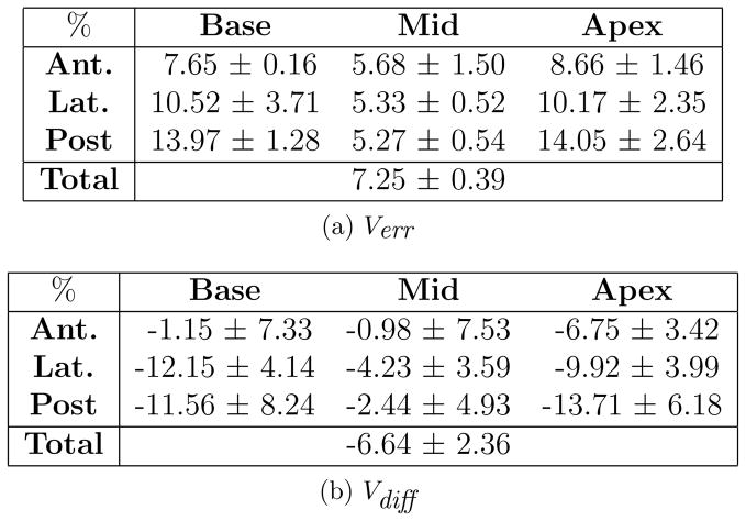
Fig. 7a and 7b show the average and inter-observer standard deviation of the absolute percent volume error and volume difference between manual and post-modified semi-automatic contours of 10 cases created by three observers. This comparison measures the amount of bias in the physicians’ contouring when segmentation is done entirely manually as opposed to when initial semi-automatic contours are given to be approved. Most of the difference between manual and post-modified segmentation is seen in the base and apex where visibility of the gland is low or absent. In these regions, the observer tends to rely more on the given semi-automatic contours. In the mid-gland region (which consists of over 50% of the prostate volume) the bias is lower and similar to the other computed errors for this region (pre- vs. post-modified semi-automatic and pre-modified semi-automatic vs. manual contours). A negative Vdiff in all regions indicates that the prostate volume created from manual contours tends to be larger than that of post-modified semi-automatic.
Figure 7.
Comparison of post-modified semi-automatic and manual prostate sectors.
Fig. 8a and 8b show the absolute percent volume error and volume difference between manual and pre-modified semi-automatic contours created on 21 cases. The average MAD and MAXD between the manual and semi-automatic contours on the mid-gland slice are respectively 1.38±0.61 mm and 3.49±1.10 mm.
Figure 8.
Comparison of pre-modified semi-automatic and manual prostate sectors.
Since the initial boundary points are selected on the mid-gland slice, and the mid-gland choice is not unique, we measured the sensitivity of the algorithm to the mid-gland slice selection. For this aim, 11 randomly selected cases were semi-automatically segmented twice by an experienced individual. In the first round, the mid-gland slice was chosen as the first candidate, i.e. the largest and most visible image of the gland. In the second round it was selected as the next best candidate, one slice above or below the selection in the first round. The whole gland volume error between manually created surfaces and surfaces created using the best mid-gland candidate was 5.56±1.21% and between manually created surfaces and surfaces created using the next best mid-gland candidate was 6.96±1.81%. Finally, the whole gland volume error between the two semi-automatic surfaces with different mid-gland slices was 6.16± 2.16%.
5.2. Repeatability
The following four figures show the inter- and intra-observer variability for manual and semi-automatic segmentation. In the presented tables, the mean and standard deviation (shown by the bars and error bars respectively) of Verr and Vdiff are derived from the average performance of each observer over all cases (i.e. from the mean value of Verr and Vdiff for each observer over all cases). It is the standard deviation that determines the observer variability in segmenting the prostate. Details of Verr and Vdiff for each observer are displayed in the appendix.
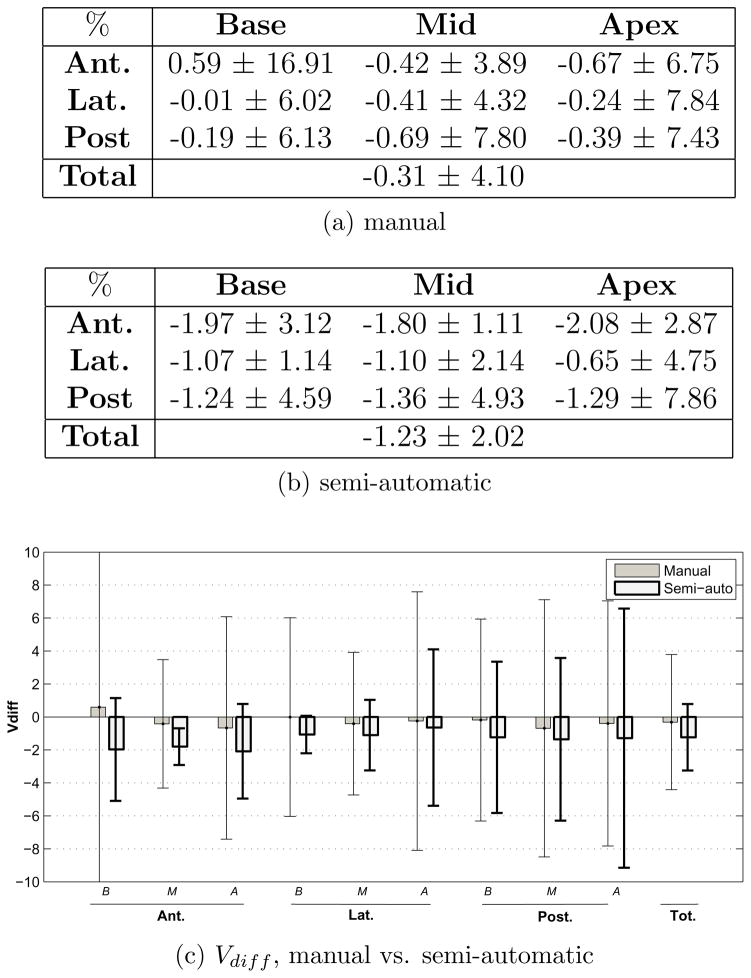
As shown in Fig. 9c and Fig. 10c, the inter-observer variability of semi-automatic contouring is less than that of manual in most of the sectors. The only sector in which manual inter-observer variability is less (as seen in both the Verr and the Vdiff bar graphs) is the posterior-apex sector. Additionally, the relatively small manual Vdiff mean values along with the large standard deviation values (Fig. 10c) compared to that of semi-automatic, indicates that most regions of the prostate can be simultaneously over-estimated by some observers while under-estimated by the others in manual segmentation. Whereas in semi-automatic segmentation, there is more agreement between observers in under-estimating or over-estimating different regions of the gland.
Figure 9.
Inter-observer variability in manual and semi-automatic contouring - as characterized by the volume error Verr.
Figure 10.
Inter-observer variability in manual and semi-automatic contouring - as characterized by the volume difference Vdiff.
Fig. 11c and Fig. 12c show the intra-observer variability in manual and semi-automatic contouring. As in inter-observer variability, in most sectors, intra-observer variability is less in semi-automatic contouring compared to that of manual. The sectors in which manual intra-observer variability is noticeably better are the anterior-apex and lateral-apex. However, similar to inter-observer variability, intra-observer variability is less on the entire gland in semi-automatic segmentation.
Figure 11.
Intra-observer variability in manual and semi-automatic contouring - as characterized by the volume error Verr.
Figure 12.
Intra-observer variability in manual and semi-automatic contouring - as characterized by the volume difference Vdiff.
A comparison of manual Verr values in Fig. 9c and Fig. 11c with Fig. 6a shows that the error between the semi-automatic contours and those modified for treatment planning is in the order of the difference in the segmentations done by different observers or by an individual at different times. Therefore, based on the above results, it is reasonable to claim that if the semi-automatic contours were not to be modified by physicians and were to be used directly for treatment planning, they are just as likely to provide adequate results as manual or modified contours.
5.3. Performance
The graphical interface used at the Vancouver Cancer Centre for semi-automatic segmentation gives the opportunity to the user to modify the initial points to best fit a 2D contour to the mid-gland image. After approval of this contour, the algorithm proceeds to the 3D shape fitting. This can be repeated until a satisfactory delineation is achieved. The contours are then exported for further brachytherapy planning to the VariSeed software (Varian Medical Systems, Palo Alto, CA).
The average duration of the semi-automatic segmentation per case (calculated for the 40 cases used in the accuracy study), from after initialization until the final contours are created is 14.36 ± 1.39s on a standard PC (Intel Xeon, 2.27 GHz, 3.23 GB RAM). Of this duration, the most time-consuming sections are the 3D tapered ellipsoid fitting, being an iterative process (2.72± 0.27s), and the image un-warping of all TRUS images(4.23±0.38s). However, with further code optimization, these durations can be reduced. The selection of the initial slices and the 7 initial points requires 32.3 ± 14.0s for one familiar to TRUS images of the prostate. The physicians using the results of this algorithm have reported an average modification time of 1–3 minutes. Their modifications are reported to mainly consist of shifting or changing the overall size of the contour (specially the base and apex) which is done with ease in the VariSeed software. Based on the above, the total segmentation duration, including initialization, is less than 1 minute and including contour modifications for prostate brachytherapy purposes, is expected to fall within the range of 2–4 minutes.
The time required for manual segmentation varies between users, and depends on their experience. An experienced radiation oncologist requires approximately 5–10 minutes per case to perform manual segmentation. Clinical fellows, during training, require up to 30 minutes for manual segmentation, but reach the 5 to 15 minute range after 1–3 months of brachytherapy training. However, a study to measure manual prostate segmentation time has not been performed
By visual observation of the pre- and post-modified contours, it was seen that out of the 369 segmented images of the 40 patients, 28% needed absolutely no modification (26%) or very little modification (2% - contour displacement of 1mm or less).
6. Conclusion
In this paper, we presented a semi-automatic prostate segmentation algorithm on TRUS images and performed various clinical studies to evaluate the algorithm. Clinical results show that the inter-observer and intra-observer variability of the semi-automatic contours are less than that of manual contours in most sectors. The regions in which the variability is higher in semi-automatic segmentation is mainly the apical region of the gland. Comparison of pre- and post-modified contours shows a percent volume error of 5.82±4.15 on the entire gland which is comparable to both the manual inter-observer (4.65 ± 0.77) and manual intra-observer (5.95 ± 1.59) variability. Comparison of post-modified semi-automatic and manual contours, a measure of physician bias when modifying the contours, shows a percent volume error of 7.25±0.39 for the whole gland. The duration of segmentation after initialization has been reduced from a few minutes (as seen in the literature) to less than 15 seconds (14.36 ± 1.39s). By including the initialization and possible modification time, the total segmentation time is less than 4 minutes. With the above results, we conclude that the proposed semi-automatic prostate segmentation method is accurate and consistent enough to replace manual segmentation of the gland. By applying slight modifications, such as removing the need for manual initialization, this method has the potential to be used as a real-time intra-operative segmentation method in the near future. This will be done in our future work.
The region-based volume measure of physicians’ modifications applied to our semi-automatic contours (Fig. 6c) suggests that our tapered ellipsoid shape assumption is reasonable. Other models based on priors, could also be implemented, and may improve segmentation in terms of accuracy. For example, a statistically obtained prostate model, which includes possible prostate shape abnormalities (e.g. due to tumors), would be a good choice. However, in addition to possibly increasing the segmentation time, such a model will complicate the process of treatment planning and treatment modification, as the plans may be assumed to change continuously with the parameters describing the prostate shape. A tapered ellipsoid parameterizes the shape with only a few parameters that are intuitive and easy to understand.
Since the semi-automatic segmentation algorithm is currently being used in practice (to this date, more than 150 patients have been treated based on our segmentation method), we will continue to analyze the growing collection of segmented prostate images. We will specify if any pattern or bias exists in the modifications and make the appropriate changes to the algorithm. Finally, we suggest the formation of a complete, randomly selected standard clinical data set. A comparison of the available segmentation methods on such a data set may be a suitable topic for further work.
Appendix
This appendix provides the manual and semi-automatic statistics of Verr and Vdiff for each observer and each sector calculated over all cases (Tables 1,2,3,4). In all tables, each row of each sector represents the values obtained from an observer.
Table 1.
Verr and Vdiff statistics for each observer over 10 cases in manual contours (inter-observer variability analysis).
| (a) Verr | |||
|---|---|---|---|
| % | Base | Mid | Apex |
| Ant. | 6.35 ± 4.92 | 3.46 ± 1.91 | 5.11 ± 2.41 |
| 10.35 ± 6.28 | 4.99 ± 2.83 | 6.99 ± 5.60 | |
| 12.17 ± 13.49 | 4.76 ± 5.86 | 4.30 ± 1.99 | |
| Lat. | 5.52 ± 1.97 | 3.34 ± 1.21 | 5.06 ± 2.60 |
| 6.87 ± 2.48 | 4.39 ± 1.65 | 6.44 ± 3.65 | |
| 4.92 ± 3.18 | 3.09 ± 0.73 | 4.58 ± 2.07 | |
| Post | 7.13 ± 4.11 | 2.89 ± 0.97 | 5.44 ± 2.40 |
| 7.62 ± 6.03 | 5.50 ± 2.82 | 3.91 ± 2.92 | |
| 5.43 ± 2.93 | 3.31 ± 1.27 | 5.44 ± 2.41 | |
| Total | 4.19 ± 0.72 | ||
| 5.54 ± 0.95 | |||
| 4.23 ± 1.64 | |||
| (b) Vdiff | |||
|---|---|---|---|
| % | Base | Mid | Apex |
| Ant. | 7.40 ± 16.18 | 3.61 ± 6.71 | 4.09 ± 10.77 |
| 13.04 ± 24.50 | −0.70 ± 11.60 | −8.39 ± 13.19 | |
| −18.66 ± 19.49 | −4.16 ± 11.66 | 2.30 ± 8.86 | |
| Lat. | 6.77 ± 9.09 | 2.13 ± 5.47 | 4.83 ± 9.74 |
| −4.74 ± 10.82 | −5.40 ± 5.87 | −9.28 ± 8.95 | |
| −2.05 ± 8.29 | 2.04 ± 3.46 | 3.72 ± 8.26 | |
| Post | 2.40 ± 15.89 | 4.08 ± 3.28 | −5.55 ± 8.42 |
| −7.18 ± 14.80 | −9.69 ± 5.22 | −3.76 ± 6.60 | |
| 4.21 ± 11.95 | 3.55 ± 4.38 | 8.13 ± 9.15 | |
| Total | 3.42 ± 4.67 | ||
| −4.71 ± 6.64 | |||
| 0.35 ± 4.54 | |||
Table 2.
Verr and Vdiff statistics for each observer over 5 cases in manual contours (intra-observer variability analysis).
| (a) Verr | |||
|---|---|---|---|
| % | Base | Mid | Apex |
| Ant. | 3.40 ± 0.99 | 2.86 ± 1.17 | 6.45 ± 3.99 |
| 17.32 ± 14.30 | 9.23 ± 6.73 | 9.74 ± 6.50 | |
| 8.59 ± 5.64 | 5.94 ± 2.01 | 7.77 ± 3.31 | |
| Lat. | 4.20 ± 1.97 | 2.98 ± 1.00 | 7.01 ± 3.00 |
| 6.66 ± 3.98 | 5.29 ± 1.93 | 8.39 ± 5.58 | |
| 9.10 ± 4.21 | 5.38 ± 0.89 | 7.78 ± 0.93 | |
| Post | 7.94 ± 6.72 | 3.29 ± 1.05 | 11.92 ± 8.77 |
| 7.47 ± 6.17 | 5.53 ± 3.25 | 8.38 ± 5.67 | |
| 6.18 ± 1.56 | 2.88 ± 1.05 | 8.93 ± 4.16 | |
| Total | 4.24 ± 1.49 | ||
| 7.39 ± 2.98 | |||
| 6.21 ± 0.48 | |||
| (b) Vdiff | |||
|---|---|---|---|
| % | Base | Mid | Apex |
| Ant. | 3.12 ± 5.37 | 2.18 ± 5.00 | 10.53 ± 11.09 |
| 17.47 ± 51.09 | 11.78 ± 25.01 | 10.58 ± 25.22 | |
| 14.18 ± 17.24 | 10.30 ± 6.20 | 5.42 ± 17.36 | |
| Lat. | −2.33 ± 4.88 | −0.76 ± 3.57 | −5.07 ± 9.98 |
| 0.59 ± 11.43 | 6.42 ± 6.93 | 10.93 ± 18.29 | |
| −10.91 ± 11.03 | 5.98 ± 9.05 | 1.91 ± 12.28 | |
| Post | 1.27 ± 23.31 | −2.59 ± 4.07 | −10.13 ± 23.58 |
| −6.71 ± 15.43 | 8.28 ± 10.57 | 1.92 ± 22.38 | |
| −8.35 ± 4.43 | 2.03 ± 4.54 | −7.74 ± 16.14 | |
| Total | −1.00 ± 2.20 | ||
| 6.35 ± 8.96 | |||
| 1.54 ± 6.65 | |||
Table 3.
Verr and Vdiff statistics for each observer over 10 cases in semi-automatic contours (inter-observer variability analysis).
| (a) Verr | |||
|---|---|---|---|
| % | Base | Mid | Apex |
| Ant. | 3.39 ± 2.28 | 1.46 ± 0.57 | 3.58 ± 2.96 |
| 2.57 ± 1.48 | 2.05 ± 0.86 | 3.11 ± 1.93 | |
| 4.08 ± 2.45 | 2.12 ± 1.11 | 3.16 ± 2.03 | |
| 3.24 ± 1.77 | 1.83 ± 1.04 | 4.49 ± 4.66 | |
| Lat. | 3.29 ± 1.76 | 1.73 ± 0.46 | 4.22 ± 3.30 |
| 2.86 ± 1.29 | 2.61 ± 1.21 | 4.59 ± 2.50 | |
| 3.57 ± 1.55 | 2.72 ± 1.52 | 4.44 ± 2.66 | |
| 3.33 ± 0.97 | 2.72 ± 2.59 | 5.33 ± 5.93 | |
| Post | 4.63 ± 2.97 | 3.31 ± 1.82 | 5.13 ± 3.75 |
| 5.62 ± 4.72 | 5.46 ± 4.53 | 8.24 ± 8.84 | |
| 4.96 ± 3.07 | 3.76 ± 2.13 | 5.76 ± 4.29 | |
| 4.61 ± 3.17 | 3.33 ± 2.64 | 5.72 ± 3.60 | |
| Total | 2.59 ± 0.86 | ||
| 3.22 ± 1.57 | |||
| 3.23 ± 1.22 | |||
| 3.11 ± 1.91 | |||
| (b) Vdiff | |||
|---|---|---|---|
| % | Base | Mid | Apex |
| Ant. | 0.59 ± 7.51 | −0.14 ± 1.96 | 0.39 ± 9.40 |
| −0.58 ± 5.18 | −2.55 ± 2.88 | −1.92 ± 6.35 | |
| −6.48 ± 5.60 | −2.26 ± 3.22 | −0.65 ± 6.06 | |
| −1.41 ± 6.51 | −2.25 ± 2.75 | −6.15 ± 9.11 | |
| Lat. | 0.37 ± 7.08 | −0.81 ± 1.70 | −1.32 ± 10.16 |
| −0.86 ± 4.68 | −2.65 ± 3.34 | −3.52 ± 8.39 | |
| −1.44 ± 6.45 | 1.82 ± 5.36 | 6.26 ± 7.04 | |
| −2.34 ± 5.55 | −2.76 ± 5.61 | −4.00 ± 12.34 | |
| Post | −4.16 ± 9.16 | −4.26 ± 5.40 | −3.53 ± 11.34 |
| −5.97 ± 11.43 | −6.22 ± 10.69 | −8.86 ± 17.73 | |
| 3.80 ± 11.26 | 4.84 ± 7.28 | 9.74 ± 11.30 | |
| 1.38 ± 10.82 | 0.22 ± 8.42 | −2.49 ± 12.89 | |
| Total | −1.10 ± 2.52 | ||
| −3.02 ± 3.46 | |||
| 1.55 ± 4.12 | |||
| −2.36 ± 4.76 | |||
Table 4.
Verr and Vdiff statistics for each observer over 5 cases in semi-automatic contours (intra-observer variability analysis).
| (a) Verr | |||
|---|---|---|---|
| % | Base | Mid | Apex |
| Ant. | 6.93 ± 5.52 | 2.14 ± 1.35 | 6.91 ± 6.35 |
| 2.05 ± 0.98 | 1.63 ± 0.31 | 2.50 ± 0.98 | |
| 4.22 ± 3.23 | 2.29 ± 0.90 | 3.86 ± 2.03 | |
| 4.00 ± 1.60 | 2.60 ± 1.32 | 7.52 ± 7.47 | |
| Lat. | 4.55 ± 2.95 | 2.56 ± 1.60 | 6.15 ± 5.18 |
| 2.73 ± 0.68 | 2.40 ± 0.46 | 3.55 ± 1.50 | |
| 5.20 ± 2.49 | 3.71 ± 2.41 | 5.35 ± 2.96 | |
| 3.81 ± 1.69 | 4.15 ± 3.51 | 9.68 ± 11.66 | |
| Post | 4.26 ± 3.12 | 1.84 ± 0.79 | 6.45 ± 4.39 |
| 2.76 ± 2.06 | 1.56 ± 0.77 | 3.48 ± 0.34 | |
| 5.18 ± 4.63 | 2.97 ± 1.61 | 5.40 ± 2.97 | |
| 4.72 ± 3.01 | 3.46 ± 2.15 | 8.82 ± 4.70 | |
| Total | 3.39 ± 1.83 | ||
| 2.24 ± 0.42 | |||
| 3.76 ± 1.85 | |||
| 4.52 ± 2.96 | |||
| (b) Vdiff | |||
|---|---|---|---|
| % | Base | Mid | Apex |
| Ant. | 14.11 ± 13.81 | 2.17 ± 3.70 | −8.75 ± 13.90 |
| −2.03 ± 3.20 | 0.97 ± 1.71 | 1.13 ± 4.62 | |
| 1.44 ± 10.46 | 0.36 ± 4.34 | 0.52 ± 5.71 | |
| 0.68 ± 6.73 | 2.87 ± 3.82 | 10.99 ± 24.11 | |
| Lat. | 7.65 ± 7.41 | 3.18 ± 2.80 | −2.76 ± 10.20 |
| −0.19 ± 5.16 | −0.68 ± 3.38 | −3.62 ± 5.29 | |
| −5.42 ± 7.72 | −2.89 ± 7.99 | 1.54 ± 9.62 | |
| 2.74 ± 3.52 | 6.06 ± 8.65 | 17.28 ± 38.72 | |
| Post | 8.49 ± 7.24 | 0.09 ± 3.95 | −7.17 ± 12.41 |
| −0.10 ± 7.04 | 1.18 ± 3.06 | −1.29 ± 7.19 | |
| −7.44 ± 9.70 | −3.09 ± 5.32 | −1.42 ± 9.82 | |
| −3.92 ± 8.56 | −2.64 ± 6.87 | −1.17 ± 21.99 | |
| Total | 2.58 ± 2.39 | ||
| −0.53 ± 2.96 | |||
| −2.31 ± 4.34 | |||
| 3.87 ± 7.94 | |||
Footnotes
Publisher's Disclaimer: This is a PDF file of an unedited manuscript that has been accepted for publication. As a service to our customers we are providing this early version of the manuscript. The manuscript will undergo copyediting, typesetting, and review of the resulting proof before it is published in its final citable form. Please note that during the production process errors may be discovered which could affect the content, and all legal disclaimers that apply to the journal pertain.
References
- Abolmaesumi P, Sirouspour MR. An interacting multiple model probabilistic data association filter for cavity boundary extraction from ultrasound images. IEEE Trans Med Imaging. 2004 Jun;23 (6):772–784. doi: 10.1109/tmi.2004.826954. [DOI] [PubMed] [Google Scholar]
- Badiei S, Salcudean SE, Varah J, Morris WJ. Prostate segmentation in 2D ultrasound images using image warping and ellipse fitting. Int Conf Med Image Comput Comput Assist Interv LNCS. 2006;4191:17–24. doi: 10.1007/11866763_3. [DOI] [PubMed] [Google Scholar]
- Bazaraa M, Sherali H, Shetty C. Nonlinear programming: theory and algorithms. Wiley-Interscience; 2006. [Google Scholar]
- Boukerroui D, Baskurt A, Noble J, Basset O. Segmentation of ultrasound images–multiresolution 2D and 3D algorithm based on global and local statistics. Pattern Recognition Letters. 2003;24 (4–5):779–790. [Google Scholar]
- Cootes T, Taylor C, Cooper D, Graham J. Active shape models-their training and application. Comput Vis Image Underst. 1995;61:38–59. [Google Scholar]
- Ecabert O, Peters J, Schramm H, Lorenz C, von Berg J, Walker MJ, Vembar M, Olszewski ME, Subramanyan K, Lavi G, Weese J. Automatic model-based segmentation of the heart in CT images. IEEE Trans Med Imaging. 2008 Sep;27 (9):1189–1201. doi: 10.1109/TMI.2008.918330. [DOI] [PubMed] [Google Scholar]
- Gong L, Pathak SD, Haynor DR, Cho PS, Kim Y. Parametric shape modeling using deformable superellipses for prostate segmentation. IEEE Trans Med Imaging. 2004 Mar;23 (3):340–349. doi: 10.1109/TMI.2004.824237. [DOI] [PubMed] [Google Scholar]
- Halpern EJ, Cochlin DL, Goldberg BB. Imaging of the Prostate. Martin Dunitz 2002 [Google Scholar]
- Hodge AC, Fenster A, Downey DB, Ladak HM. Prostate boundary segmentation from ultrasound images using 2D active shape models: optimisation and extension to 3D. Comput Methods Programs Biomed. 2006 Dec;84 (2–3):99–113. doi: 10.1016/j.cmpb.2006.07.001. [DOI] [PubMed] [Google Scholar]
- Hu N, Downey DB, Fenster A, Ladak HM. Prostate boundary segmentation from 3D ultrasound images. Med Phys. 2003 Jul;30 (7):1648–1659. doi: 10.1118/1.1586267. [DOI] [PubMed] [Google Scholar]
- Huang X, Metaxas DN. Metamorphs: deformable shape and appearance models. IEEE Trans Pattern Anal Mach Intell. 2008 Aug;30 (8):1444–1459. doi: 10.1109/TPAMI.2007.70795. [DOI] [PubMed] [Google Scholar]
- Jendoubi A, Zeng J, Chouikha M. Top-down approach to segmentation of prostate boundaries in ultrasound images. Applied Imagery Pattern Recognition Workshop, 2004. Proceedings. 33rd; 2004. pp. 145–149. [Google Scholar]
- Kachouie NN, Fieguth P, Rahnamayan S. An elliptical level set method for automatic TRUS prostate image segmentation. Proc. IEEE International Symposium on Signal Processing and Information Technology; Aug, 2006. pp. 191–196. [Google Scholar]
- Ladak HM, Mao F, Wang Y, Downey DB, Steinman DA, Fenster A. Prostate boundary segmentation from 2D ultrasound images. Med Phys. 2000 Aug;27 (8):1777–1788. doi: 10.1118/1.1286722. [DOI] [PubMed] [Google Scholar]
- Mahdavi S, Salcudean SE. 3D prostate segmentation based on ellipsoid fitting, image tapering and warping. Conf Proc IEEE Eng Med Biol Soc. 2008;1:2988–2991. doi: 10.1109/IEMBS.2008.4649831. [DOI] [PubMed] [Google Scholar]
- Mahdavi SS, Morris WJ, Spadinger I, Chng N, Goksel O, Salcudean SE. 3D prostate segmentation in ultrasound images based on tapered and deformed ellipsoids. Med Image Comput Comput Assist Interv LNCS. 2009;5762 (Pt 2):960–967. doi: 10.1007/978-3-642-04271-3_116. [DOI] [PubMed] [Google Scholar]
- Morris WJ, Keyes M, Palma D, Spadinger I, McKenzie MR, Agranovich A, Pickles T, Liu M, Kwan W, Wu J, Berthelet E, Pai H. Population-based study of biochemical and survival outcomes after permanent 125I brachytherapy for low- and intermediate-risk prostate cancer. Urology. 2009 Apr;73(4):860–5. doi: 10.1016/j.urology.2008.07.064. discussion 865–7. [DOI] [PubMed] [Google Scholar]
- Nag S, Ciezki JP, Cormack R, Doggett S, DeWyngaert K, Edmundson GK, Stock RG, Stone NN, Yu Y, Zelefsky MJ Clinical Research Committe, A. B. S. Intraoperative planning and evaluation of permanent prostate brachytherapy: report of the american brachytherapy society. Int J Radiat Oncol Biol Phys. 2001 Dec;51 (5):1422–1430. doi: 10.1016/s0360-3016(01)01616-9. [DOI] [PubMed] [Google Scholar]
- Nanayakkara ND, Samarabandu J, Fenster A. Prostate segmentation by feature enhancement using domain knowledge and adaptive region based operations. Phys Med Biol. 2006 Apr;51 (7):1831–1848. doi: 10.1088/0031-9155/51/7/014. [DOI] [PubMed] [Google Scholar]
- Nascimento JC, Marques JS. Robust shape tracking with multiple models in ultrasound images. IEEE Trans Image Process. 2008 Mar;17 (3):392–406. doi: 10.1109/TIP.2007.915552. [DOI] [PubMed] [Google Scholar]
- Noble JA, Boukerroui D. Ultrasound image segmentation: a survey. IEEE Trans Med Imaging. 2006 Aug;25 (8):987–1010. doi: 10.1109/tmi.2006.877092. [DOI] [PubMed] [Google Scholar]
- Pathak SD, Haynor DR, Kim Y. Edge-guided boundary delineation in prostate ultrasound images. IEEE Trans Med Imaging. 2000 Dec;19 (12):1211–1219. doi: 10.1109/42.897813. [DOI] [PubMed] [Google Scholar]
- Penna MA, Dines KA, Seip R, Carlson RF, Sanghvi NT. Modeling prostate anatomy from multiple view TRUS images for image-guided HIFU therapy. IEEE Trans Ultrason Ferroelectr Freq Control. 2007 Jan;54 (1):52–69. doi: 10.1109/tuffc.2007.211. [DOI] [PubMed] [Google Scholar]
- Pluempitiwiriyawej C, Moura JMF, Fellow, Wu Y-JL, Ho C. STACS: new active contour scheme for cardiac MR image segmentation. IEEE Trans Med Imaging. 2005 May;24 (5):593–603. doi: 10.1109/TMI.2005.843740. [DOI] [PubMed] [Google Scholar]
- Shen D, Zhan Y, Davatzikos C. Segmentation of prostate boundaries from ultrasound images using statistical shape model. IEEE Trans Med Imaging. 2003 Apr;22 (4):539–551. doi: 10.1109/TMI.2003.809057. [DOI] [PubMed] [Google Scholar]
- Thevenaz P, Unser M. Snakuscules. IEEE Trans Image Process. 2008 Apr;17 (4):585–593. doi: 10.1109/TIP.2007.914742. [DOI] [PubMed] [Google Scholar]
- Tutar IB, Pathak SD, Gong L, Cho PS, Wallner K, Kim Y. Semiautomatic 3-D prostate segmentation from TRUS images using spherical harmonics. IEEE Trans Med Imaging. 2006 Dec;25 (12):1645–1654. doi: 10.1109/tmi.2006.884630. [DOI] [PubMed] [Google Scholar]
- Varah JM. Least squares data fitting with implicit functions. BIT. 1996;36 (4):842–854. [Google Scholar]
- Yezzi A, Kichenassamy S, Kumar A, Olver P, Tannenbaum A. A geometric snake model for segmentation of medical imagery. IEEE Trans Med Imaging. 1997 Apr;16 (2):199–209. doi: 10.1109/42.563665. [DOI] [PubMed] [Google Scholar]
- Zaim A. An edge-based approach for segmentation of prostate ultra-sound images using phase symmetry. ISCCSP 2008. 2008:10–13. [Google Scholar]
- Zhan Y, Shen D. Deformable segmentation of 3-D ultrasound prostate images using statistical texture matching method. IEEE Trans Med Imaging. 2006 Mar;25 (3):256–272. doi: 10.1109/TMI.2005.862744. [DOI] [PubMed] [Google Scholar]
- Zhan Y, Shen D, Zeng J, Sun L, Fichtinger G, Moul J, Davatzikos C. Targeted prostate biopsy using statistical image analysis. IEEE Trans Med Imaging. 2007 Jun;26 (6):779–788. doi: 10.1109/TMI.2006.891497. [DOI] [PubMed] [Google Scholar]


