Abstract
A detailed protocol for crystallizing membrane proteins by using lipidic mesophases is described. This method has variously been referred to as the lipidic cubic phase or in meso method. The method has been shown to be quite versatile in that it has been used to solve X-ray crystallographic structures of prokaryotic and eukaryotic proteins, proteins that are monomeric, homo- and hetero-multimeric, chromophore-containing and chromophore-free, and alpha-helical and beta-barrel proteins. Recent successes using in meso crystallization are the human engineered beta2-adrenergic and adenosine A2a G protein-coupled receptors. Protocols are presented for reconstituting the membrane protein into the monoolein-based mesophase, and for setting up crystallizations in the manual mode. Additional steps in the overall process, such as crystal harvesting, are to be addressed in future video articles. The time required to prepare the protein-loaded mesophase and to set up a crystallization plate manually is about one hour.
Keywords: Biochemistry, Issue 45, membrane protein, in meso, membrane, crystallization, lipidic mesophases, manual
Protocol
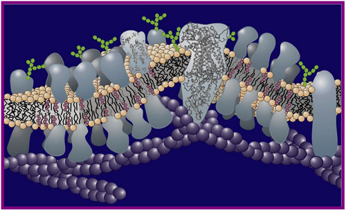
An important focus in the area of structural and functional biology is the biological membrane (Figure 1). The membrane, which surrounds the cell and sub-cellular organelles when present, is a molecularly thin structure just two lipid molecules across and is studded with proteins. Structure and function as applied to both lipid and proteins are of interest. However, the focus of this article is restricted to membrane proteins.
A better understanding of how membrane proteins function at a molecular level is sought for two reasons. Firstly, there is the intellectual satisfaction in knowing how they work. Secondly, by knowing how a protein works, there is always the prospect of being able to fix it should it malfunction or of improving or even modifying it for particular applications. Drug design is an obvious outcome of this type of work. One approach to figuring how a membrane protein works at a molecular level is to determine its structure. This involves establishing the location in 3-dimensional space of all atoms, or at least all non-hydrogen atoms, that make up the protein. The method we use for this purpose is macromolecular X-ray crystallography (MX). Figure 2 shows an example of a membrane protein whose structure was determined using MX. A diffraction quality crystal of the protein is required to do MX.
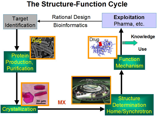
Clearly, there are many steps involved in structure determination using macromolecular crystallography. This is illustrated in Figure 3. Typically, these include identifying a membrane protein target, and then producing, purifying and crystallizing it. Diffraction measurements are performed on the crystal using a home or a synchrotron X-ray source. The diffraction data are processed yielding an electron density map that is then fitted with a molecular model. The model, when refined, can be used to explore the mechanism of action of the protein and for structure-based drug design.
The focus of this article is to show how we produce diffraction quality crystals of membrane proteins using lipidic mesophases, by the so-called in meso method. A recent review of the method and its scope is available in Reference 1 (Caffrey, 2009). The step-by-step protocol we will follow here is described in Reference 2 (Caffrey and Cherezov, 2009).
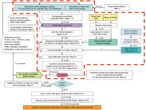
A flowchart summarizing the steps involved in and time required for setting up an in meso membrane protein crystallization trial is shown in Figure 4. This article covers those steps enclosed by dashed red lines.
Part 1: Preparing the Crystallization Plates
Position a silanized microscope slide on the work bench.
Remove the protective paper cover from one surface of a strip of perforated double stick spacer tape (commercially available, see Table of Specific Reagents and Equipment below).
Place the tape, sticky side down, in contact with the surface of the slide.
Pressure-seal the tape to the slide using a brayer or roller. Aluminum foil can be placed between the tape and the roller to protect the base of the wells.
Remove the second paper cover from the tape to expose its upper sticky surface.
Place individual silanized coverslips in close proximity to the plate for fast and efficient sealing of wells as soon as loading is complete.
Part 2: Preparing the Lipid Syringe
Place the lipid (often monoolein) in a temperature-controlled block at 45 °C for 3 minutes to render it molten.
While the lipid is melting prepare two 100-μL gas-tight Hamilton syringes for use in the lipid-protein mixing step. Remove the Teflon ferrule from the syringe that will contain the protein solution. Place the syringe that will hold the lipid next to it (leaving its ferrule in place).
Connect the coupler (see Table of Specific Reagents and Equipment below and Reference 3 (Cheng et al., 1998)) to the lipid syringe. Finger-tighten the coupler to the syringe but do not over-tighten. Remove the plunger from the barrel of the lipid syringe.
Note that the lipid must be molten before proceeding. Set the pipette to 30 μL and slowly take up approximately 30 μL of molten lipid. Slowly deliver as much of the molten lipid as you can into the open end of the syringe taking care not to introduce air gaps.
Place the plunger into the barrel in contact with the molten lipid and slowly advance the plunger up the barrel with the syringe held vertically as demonstrated in the video. Air bubbles that may be trapped inadvertently should rise in the process and be released.
Carefully determine the volume of lipid in the syringe by reading the markings on the syringe barrel.
Slide the ferrule onto the needle extending from the coupler. Use the plunger to force the molten lipid up the barrel and slowly and gently into the needle at the core of the coupler.
Part 3: Preparing the Protein Syringe
The protein solution should be spun at 14,000 g for 5 to 10 minutes at 4 °C to remove large aggregates before setting up crystallization trials. Remove the protein solution from the ice and allow it to equilibrate at room temperature.
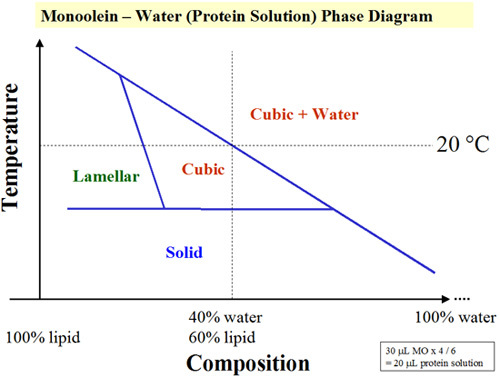
Calculate the volume of protein solution to use to form the cubic phase at or close to full hydration. For monoolein at 20 °C, full hydration with water occurs at close to 40 % water (by mass) as in the phase diagram5 (Figure 5).
With a 25 or 50 μL Hamilton syringe take up the required volume of protein solution. Transfer the solution onto the Teflon tip of the plunger in the barrel of the protein syringe taking care to avoid air bubbles.
Carefully withdraw the needle and measure the volume of protein solution in the syringe. It should match the value delivered in the previous step.
Slowly inch the protein solution up the barrel to end up flush with its open end.
Screw the protein syringe into the open end of the coupler attached to the lipid syringe. It is critical that the device not be excessively tightened. Over-tightening the assembled mixing device at this stage will damage the ferrules and cause leaking. Under-tightening will also lead to leaking.
Part 4: Mixing Protein Solution and Lipid: Making the Mesophase
To effect mixing, advance the plunger on the protein side of the assembled mixing unit to its limit, with the thumb or index finger driving the protein solution out of the protein syringe, through the coupler and into the lipid syringe.
The plunger on the lipid side is now used to drive the contents of the lipid syringe back through the coupler and into the protein syringe.
The process is repeated many times; occasionally, a hundred passages or more are required to produce a homogenous mesophase. At the start of mixing, movement of material back and forth through the coupler can be uneven and, at times, extra force is needed to effect mixing. Initial mixing is usually accompanied by the development of a non-uniform cloudiness in the sample. As homogenization progresses, the texture becomes more uniform and characteristic of the viscous cubic phase, as does the visual appearance of the emerging cubic mesophase.
If conditions are appropriate and the cubic phase forms, the dispersion should appear optically transparent in the syringe barrel. Thus, the markings on the syringe barrel should be clearly legible through the mesophase in the barrel.
Very slight cooling of the sample during mixing by placing the syringe mixer for a short time on ice can accelerate homogenization and the achievement of transparency. However, it is important not to overcool the sample.
Care should be taken to avoid extremely vigorous mixing, as this can cause sample temperature to rise due to frictional heating3.
Part 5: Loading the Dispenser
Remove the needle and the plunger from a 10-μL Hamilton syringe. Leave the Teflon ferrule in place.
Remove the retaining nut from the dispenser with the aid of a small coin.
With the ratchet arm fully withdrawn, insert the syringe - without its plunger and needle - through the holding ring of the dispenser.
Replace the retaining nut, gasket side facing the syringe, and screw it in tightly on the open end of the syringe. Care should be taken to ensure the syringe is properly centered in the holding ring and that the barrel is aligned parallel to the ratchet arm. Both can be judged by eye. These two requirements are critical to avoid leakage.
Pass the plunger through the gripping ring with the gripper nut unscrewed a few turns and guide the plunger into the open end of the syringe. Depress the ratchet arm fully. Move the plunger into the barrel and check that it travels freely and true in the barrel. It may help to loosen the screw on the guide bar to facilitate the plunger moving freely. Make sure that it does. Depress the plunger until its Teflon tip aligns with the zero μL graduation mark on the barrel. If the screw on the guide bar was loosened, retighten it and recheck that the plunger moves freely.
Move the plunger on one side of the assembled mixing unit to the zero μL graduation mark to transfer the mesophase to the other syringe and the coupler.
Disconnect the empty syringe (with its ferrule in place) from the mixing unit and immediately connect the loaded syringe - with the coupler attached - to the threaded termination of the 10-μL dispensing syringe. The degree of tightness with which coupling is done is critical, as already noted.
Load the dispensing syringe by depressing the plunger of the 100-μL syringe so that the mesophase transfers through the coupler.
Secure a short, flat-tipped needle to the steel termination of the dispensing syringe and carefully tighten it in place.
Clamp the plunger to the ratchet arm by tightening the nut in the gripping ring. Care should be taken not to over-tighten the nut, as this can score and deform the plunger rendering it unusable. It is important that the travel range provided to the ratchet arm in the clamped condition be limited to no more than an inch, as demonstrated in the video. Beyond this, the plunger will have a tendency to buckle and delivery can fail.
Depress the ratchet drum several times to advance the plunger in the barrel, thereby filling the void volume of the needle and loading the needle. This step should be repeated (up to ten times) until a continuous string of the mesophase emerges from the tip of the needle.
Crystallization trials should commence immediately, as some proteins are unstable in the cubic phase without added precipitant.
Part 6: Setting up Crystallization Plates
Place a multi-well crystallization plate and coverslip on a surface raised a few inches above the work bench for ease of loading. Optimal contrast and enhanced visibility are achieved when the surface is slightly dark.
Homogenize the precipitant solutions and uncap the vials. Set the precipitant dispensing pipet to 1 μL.
With the dispensing syringe held vertically in one hand, use the free hand to position the needle tip in the center and directly above the base of well number 1. Press the button on the repeating dispenser to expel a bolus of mesophase onto the glass surface. The bolus volume is 200 nL when the standard repeating dispenser is used with a 10-μL syringe. The tip of the needle should be no more than a few hundred micrometers above the base of the well to ensure proper delivery.
After 4 adjacent wells are loaded with mesophase, place 1 μL of precipitant solution on top of each mesophase bolus using a 2-μL pipet and standard disposable tips.
As quickly as possible, place a coverslip squarely over the filled wells to cover them uniformly. To effect a water-tight seal, use a spatula to apply pressure to the coverslip where it makes contact with the exposed sticky surface of the spacer tape.
The mesophase and precipitant dispensing process can be repeated until all wells on the plate are loaded and sealed.
Label the plate clearly for tracking purposes. Light-sensitive proteins are usually handled by wrapping the plates in aluminum foil before placing them in the incubation chamber.
Place the plates in a temperature-controlled chamber, usually at 20 °C.
On a regular schedule, inspect the wells for crystal growth using a Polarized Light Microscope with a 10 or 20-fold objective. The schedule used in the author's lab is as follows: day 0, 1, 2, 3, 5, 7, 14, 21, 30 and 60 post-setup. Carefully inspect the mesophase bolus adjusting the depth of focus within the 0.14-mm-thick sample. Examination should be done both in normal light and between crossed-polarizers.
Part 7: Representative Results
The appearance of the resulting crystals will vary with the inherent color of the membrane protein, the polarization of the light used for inspection (or lack thereof) and the method and quality of illumination. Figure 6 shows several possible crystal appearances. Naturally colored membrane proteins growing in meso when viewed with normal light can look like those shown in Figure 6 (Panels b and d). Colorless membrane protein crystals growing in the cubic phase when viewed with normal light can look like those shown in Figure 6 (Panel e). Finally, colorless membrane protein crystals growing in meso when viewed with polarized light can look like Figure 6 (Panels a and c).
The next steps in the overall process of structure determination are to harvest and cryo-cool the crystals and to record and analyze X-ray diffraction from them. These topics are to be covered in separate JoVE articles.
 Figure 1. Schematic representation of a biological membrane showing the lipid bilayer in and on which are situated a variety of proteins.
 Figure 2. The structure of the vitamin B12 transporting protein, BtuB, solved using MX and crystals grown by the in meso method6 illustrated in this JoVE article.
 Figure 3. The structure-function cycle illustrates many of the steps involved in obtaining and utilizing complete structural information about a protein.
 Figure 4. The flowchart summarizes the steps involved in the production of membrane protein crystals by the in meso method. Only those steps surrounded by the dashed red line are covered in this JoVE article. From Reference 2.
 Figure 5. A simplified temperature-composition phase diagram for the lipid (monoolein)/water system. Crystallization trials are set up at 20 °C where the lipid saturates with water at 40 % hydration. The detailed phase diagram is available in Reference 5.
 Figure 6. Crystals of membrane proteins growing in the lipidic mesophase. (a) vitamin B12 transporting protein, BtuB6, (b) light-harvesting complex II7, (c) the adhesin/invasin OpcA8, (d) bacteriorhodopsin9, (e) a carbohydrate transporter from Pseudomonas. Images recorded with normal light (b,d,e) and between crossed polarizers (a,c).
Discussion
The cubic phase is a delicate and dynamic environment that can change drastically with the alteration of a number of variables. It is not possible to give a description of the setup of in meso crystallization trials in the manual mode that describes all potential pitfalls. However, many difficulties can be avoided by practicing the technique before applying it to expensive protein solutions and by using moderation in pressure applied to syringes during mixing. Done correctly, the in meso method can yield crystals of a wide variety of proteins, the number of which is constantly increasing.
The description given here of the setup of in meso crystallization trials is focused on the manual mode. The process can be, and often is modified to facilitate automated setup of the crystallization plates in those cases that require large-scale screening of crystallization conditions.
Acknowledgments
There are many who contributed to this work and most are from the Caffrey Membrane Structural and Functional Biology Group, both past and present members. To all we extend our warmest thanks and appreciation. This work was supported in part by grants from Science Foundation Ireland (07/IN.1/B1836), the National Institutes of Health (GM75915), and the University of Limerick.
References
- Caffrey M. Crystallizing membrane proteins for structure determination. Use of lipidic mesophases. Annu. Rev. Biophys. 2009;38:29–51. doi: 10.1146/annurev.biophys.050708.133655. [DOI] [PubMed] [Google Scholar]
- Caffrey M, Cherezov V. Crystallising membrane proteins in lipidic mesophases. Nat. Protoc. 2009;4:706–731. doi: 10.1038/nprot.2009.31. [DOI] [PMC free article] [PubMed] [Google Scholar]
- Cheng A, Hummel B, Qiu H, Caffrey M. A simple mechanical mixer for small viscous lipid-containing samples. Chem. Phys. Lipids. 1998;95:11–21. doi: 10.1016/s0009-3084(98)00060-7. [DOI] [PubMed] [Google Scholar]
- Cherezov V, Caffrey M. Nano-volume plates with excellent optical properties for fast, inexpensive crystallization screening of membrane proteins. J. Appl. Cryst. 2003;36:1372–1377. [Google Scholar]
- Qiu H, Caffrey M. The phase diagram of the monoolein/water system: metastability and equilibrium aspects. Biomaterials. 2000;21:223–234. doi: 10.1016/s0142-9612(99)00126-x. [DOI] [PubMed] [Google Scholar]
- Cherezov V. In meso structure of the cobalamin transporter, BtuB, at 1.95 A resolution. J. Mol. Biol. 2006;364:716–734. doi: 10.1016/j.jmb.2006.09.022. [DOI] [PMC free article] [PubMed] [Google Scholar]
- Cherezov V, Clogston J, Papiz MZ, Caffrey M. Room to move: crystallizing membrane proteins in swollen lipidic mesophases. J. Mol. Biol. 2006;357:1605–1618. doi: 10.1016/j.jmb.2006.01.049. [DOI] [PubMed] [Google Scholar]
- Cherezov V. In meso crystal structure and docking simulations suggest an alternative proteoglycan binding site in the OpcA outer membrane adhesin. Proteins. 2008;71:24–34. doi: 10.1002/prot.21841. [DOI] [PubMed] [Google Scholar]
- Cherezov V, Peddi A, Muthusubramaniam L, Zheng YF, Caffrey M. A robotic system for crystallizing membrane and soluble proteins in lipidic mesophases. Acta Crystallogr. D Biol. Crystallogr. 2004;60:1795–1807. doi: 10.1107/S0907444904019109. [DOI] [PubMed] [Google Scholar]


