

Abstract
Purpose: Design and validate an efficient dual-slot coaxial microwave ablation antenna that produces an approximately spherical heating pattern to match the shape of most abdominal and pulmonary tumor targets.Methods: A dual-slot antenna geometry was utilized for this study. Permutations of the antenna geometry using proximal and distal slot widths from 1 to 10 mm separated by 1–20 mm were analyzed using finite-element electromagnetic simulations. From this series, the most optimal antenna geometry was selected using a two-term sigmoidal objective function to minimize antenna reflection coefficient and maximize the diameter-to-length aspect ratio of heat generation. Sensitivities to variations in tissue properties and insertion depth were also evaluated in numerical models. The most optimal dual-slot geometry of the parametric analysis was then fabricated from semirigid coaxial cable. Antenna reflection coefficients at various insertion depths were recorded in ex vivo bovine livers and compared to numerical results. Ablation zones were then created by applying 50 W for 2–10 min in simulations and ex vivo livers. Mean zone diameter, length, aspect ratio, and reflection coefficients before and after heating were then compared to a conventional monopole antenna using ANOVA with post-hoc t-tests. Statistical significance was indicated for P < 0.05.Results: Antenna performance was highly sensitive to dual-slot geometry. The best-performing designs utilized a proximal slot width of 1 mm, distal slot width of 4 mm ± 1 mm and separation of 8 mm ± 1 mm. These designs were characterized by an active choking mechanism that focused heating to the distal tip of the antenna. A dual-band resonance was observed in the most optimal design, with a minimum reflection coefficient of −20.9 dB at 2.45 and 1.25 GHz. Total operating bandwidth was greater than 1 GHz, but the desired heating pattern was achieved only near 2.45 GHz. As a result, antenna performance was robust to changes in insertion depth and variations in relative permittivity of the surrounding tissue medium. In both simulations and ex vivo liver, the dual-slot antenna created ablations greater in diameter than a coaxial monopole (35 mm ± 2 mm versus 31 mm ± 2 mm; P < 0.05), while also shorter in length (49 mm ± 2 mm versus 60 mm ± 6 mm; P < 0.001) after 10 min. Similar results were obtained after 2 and 5 min as well.Conclusions: Dual-slot antennas can produce more spherical ablation zones while retaining low reflection coefficients. These benefits are obtained without adding to the antenna diameter. Further evaluation for clinical microwave ablation appears warranted.
Keywords: thermal ablation, microwave ablation, interstitial antenna
INTRODUCTION
Thermal ablation is a promising technique for treating tumors in many organs. It is most commonly associated with the treatment of unresectable benign and malignant tumors in the liver, renal cell carcinomas, and pulmonary nodules.1, 2, 3 Ablative techniques can be applied at open surgery, laparoscopy, or percutaneously using image-guidance and monitoring. Once the thermal ablation applicator is placed into the target site, energy is applied to elevate temperatures in the tissue surrounding the applicator for enough time to cause coagulative necrosis. The time-temperature history, or thermal dose, dictates the likelihood of cell death, with temperatures in excess of approximately 60 °C associate with nearly instantaneous coagulative necrosis.4
When compared to radiofrequency electrical current—the most widely used and researched energy for thermal ablation to date—microwaves offer several important advantages: faster heat generation over a larger treatment volume, increased ability to penetrate charred or desiccated tissue, less susceptibility to local heat sinks, improved multiple applicator options, and no ground pads.5, 6, 7 However, many systems in use today create ablation zones whose length along the antenna axis is substantially greater than the diameter transverse to the antenna axis. These elongated ablations are undesirable in many clinical scenarios. Most tumors of the liver, kidney, and lung indicated for thermal ablation are focal and exhibit a relatively spherical morphology. Therefore, when using a single applicator, the desired ablation zone is more spherical, with relatively equal length and transverse diameter. Matching the ablation zone to the tumor may help prevent complications associated with thermal damage of adjacent normal tissue noted in previous studies.8, 9
Several interstitial antennas have been presented in the literature for microwave ablation and the related field of interstitial microwave hyperthermia, including coaxial monopoles, dipoles, annular slots, and triaxial and looped designs. However, many of these designs are characterized by elongated heating patterns.10, 11, 12, 13, 14, 15, 16 Coaxial sleeve chokes, which may be floating or attached to the outer conductor of the coaxial cable, can help confine the heating pattern to the distal aspect of the antenna, thereby reducing backwards heating along the antenna shaft.17, 18, 19 These choked designs are not without drawbacks, as they increase the antenna diameter and potentially increase power reflections from the antenna. Increased antenna diameter may lead to greater incidence of complications when applied percutaneously in some organs.20 In addition, since the choke itself is typically a quarter or half-wavelength, the length of ablations produced with choked designs may not be appreciably shorter than conventional designs.
Coaxial slot antennas, some with multiple slots, have been previously described in the literature for microwave tissue heating.12, 21 To date, these designs have been presented without supporting documentation of the design process or analysis of performance relative to antenna geometry. As a result, the operation of coaxial slot antennas is not well-described, and methods to improve their performance are lacking. Here is presented a coaxial slot antenna with two slots designed to simultaneously minimize both reflected power and ablation length without the addition of chokes. The objective of this study was to analyze the dual-slot antenna using electromagnetic simulations and then to determine the most optimal geometry to produce low reflected power and highly spherical heating pattern. The most optimal design was then validated against a conventional monopole antenna by numerical simulations and ex vivo experiments.
METHODS
Parametric analysis of antenna geometry
The dual-slot antenna structure incorporates two annular slots of widths G1 (proximal slot) and G2 (distal slot) separated by a length, L, which is nominally one-half wavelength of the input frequency in the ambient tissue medium (Fig. 1). The distal slot abuts a cap connected to the inner conductor of the coaxial cable, which creates a reflective interface. An analytical transmission line model can be used to optimize the input impedance of coaxial slot antennas; however, as will be confirmed in the results section, identifying resonant modes is not wholly relevant for microwave ablation applications.22 The spatial pattern of heating produced by the antenna is perhaps more important. Therefore, numerical simulation was used in this study to analyze the influence of slot width size and separation length on both antenna efficiency and spatial heating pattern.
Figure 1.

Schematic of the dual-slot antenna design. Two slots of width G1 and G2 are separated by a length, L. The distal slot abuts a cap at the end of the antenna.
Based on preliminary investigations, we determined that the optimal design should be achievable with slot widths of 1–10 mm and separation lengths of 1–20 mm. Our analysis was limited to 1 mm of these dimensions since fabrication tolerance was estimated to be approximately ±0.5 mm. Analysis was performed using the finite-element method to solve Maxwell’s equations in the transverse magnetic (TM) propagation mode (Comsol Multiphysics 3.5a; Burlington, MA)
| (1) |
where E is the electric field vector (V∕m), ω is angular frequency (rad∕s), ɛr is the relative permittivity (F∕m), and σ is effective conductivity (S∕m). Simulations were performed in a two-dimensional domain by assuming rotational symmetry about the longitudinal axis of the antenna. This assumption allowed faster computation and is valid when the antenna is applied in a region without substantial dielectric heterogeneity. Metallic components were assumed to be perfect electrical conductors, and the coaxial dielectric material was assumed to be lossless polytetrafluoroethylene (PTFE). Liver properties were taken from the available literature at 20 °C for comparison to later room-temperature experiments.23, 24 Perfectly matched layers were assumed for all exterior boundaries. Input power was set to 1 W at 2.45 GHz in all simulations. Adaptive triangular mesh elements were populated using a maximum element size of 2 mm in the liver domain. Total mesh size was approximately 10 000 elements. All simulations were performed on a single workstation with a 2.93 GHz Intel W3540 processor and 12 GB RAM with up to eight permutations computed simultaneously in parallel threads.
To determine the most optimal antenna design, an objective (cost) function, Ψ, was defined using two independent variables for reflection coefficient, G(dB), and aspect ratio of heating pattern, AR
| (2) |
where A1 and A2 represent slopes of the sigmoidal curves at inflection points B1 and B2. The heating aspect ratio was defined as twice the maximum radial dimension (diameter) divided by the longitudinal dimension (length) of the SAR = 30 W∕kg isocontour in simulated SAR maps. Preliminary investigations showed that this SAR isocontour was a good approximation to the actual ablation zone produced after several minutes of heating and, therefore, a reasonable choice for the purposes of antenna analysis and comparison.
The sigmoidal terms in Eq. 2 were used to weight reflection coefficient and heating aspect ratio from a practical perspective; that is, reflection coefficients less than −20 dB or heating aspect ratios greater than 0.9 provide diminishing returns. Similarly, designs with reflection coefficients greater than −10 dB or heating aspect ratios less than 0.5 are either too reflective or too elongated for precise ablation of the approximately spherical tumors found in the abdomen. With these constraints in mind, the coefficient values selected for Eq. 2 were: A1 = 0.5, A2 = −10, B1 = −15, and B2 = 0.7 (Fig. 2). The objective function value was calculated for each permutation in the parametric analysis, with the lowest cost indicating the most optimal designs.
Figure 2.

Cost function terms for reflection coefficient (black line, upper x-axis) and heating aspect ratio (gray line, lower x-axis) reflect the desire to maximize antenna efficiency and heating sphericity with using smooth functions and practical limits.
Characterization of most optimal designs
The most optimal design was then characterized further using numerical simulations and experiments in normal ex vivo bovine liver at 20 °C. Antenna reflection coefficient was numerically analyzed assuming frequency-dependent liver permittivity and compared to those measured from 0.5 to 6.0 GHz using a vector network analyzer (8753ES; Agilent Technologies, Palo Alto, CA).24 Open-short-load calibration and time-domain gating were used so that the experimental measurement plane matched that of numerical simulations. To evaluate the effect of variable insertion depth encountered in clinical percutaneous or surgical procedures, separate measurements were obtained with the antenna tip inserted 2–7 cm into the tissue block in 1 cm increments.
The sensitivity of each antenna to variations in ambient tissue permittivity was also evaluated. The relative permittivity of liver can vary by more than ±20% depending on tissue pathology or temperatures in the ablation zone.25, 26 Such changes affect power delivery and spatial heating pattern; therefore, baseline permittivity was varied by ± 30% in simulations to evaluate the effect on antenna performance. The mean percent difference in reflection coefficient between all variations and changes in heating pattern were noted.
Finally, heating produced by dual-slot and monopole antennas was simulated assuming an input power of 50 W at 2.45 GHz for 600 s. Temperature-dependent dielectric properties were used to improve the agreement between simulation and experiment.25 Reflection coefficients and spatial maps of heat generation and temperature were generated throughout to monitor the effects of changing tissue properties.
Simulations were validated against experimental ablations created in approximately 6 cm × 9 cm × 6 cm blocks of normal ex vivo bovine liver initially at 20 °C. Antennas were fabricated from 0.085′ semirigid coaxial cable (UT-85C; Micro-Coax LLC, Pottstown, PA). The dual-slot design was fabricated to match the dimensions of the optimal geometry, while coaxial monopoles were created with a 14 mm radiating segment.10 Microwave power was provided by a continuous-wave 2.45 GHz magnetron source (MG300; Cober-Muegge, Norwalk, CT) and transferred to the antennas via RG-400 coaxial cables. Generator output power control was employed to offset cable losses and ensure 50 W delivery to the antenna. Heating times of 120, 300, and 600 s were tested.
Each ablation zone was sectioned along the antenna axis to evaluate its maximum dimensions transverse to the antenna (diameter) and along the antenna (length), with the ablation aspect ratio defined as diameter divided by length. Each experiment was replicated six times for statistical analysis. Differences in size metrics, aspect ratio, and reflection coefficients measured before and after the ablation were detected amongst time and antenna design using one-way ANOVA. Tukey’s post-hoc tests were used to compare groups directly. P-values less than 0.05 were considered significant.
RESULTS
Parametric analysis of antenna geometry
Each simulation required approximately 4 s to complete, and the entire parametric space was analyzed in approximately 30 min. The most optimal design based on the objective function in Eq. 2 was realized with G1 = 1 mm, L = 8 mm, and G2 = 4 mm (Fig. 3). The top ten designs are detailed in Table TABLE I.. From these, it was clear that antenna performance was highly sensitive to the proximal slot width, G1, but slightly less sensitive to the distal slot width, G2, or separation distance, L. Therefore, the most optimal design with tolerances accepting nearly equivalent performance metrics was G1 = 1 mm, L = 8 mm ± 1 mm, and G2 = 4 mm ± 1 mm.
Figure 3.

Three-dimensional scatterplot of objective function values for all input permutations. More desirable (lower) values are noted by large dark dots. This plot allows visualization of the influence of each geometric parameter, with the best objective values clustered around the G1 = 1 mm, L = 8 mm, G2 = 4 mm region.
TABLE I.
Top 0.5% of simulated designs by objective function value, with relevant performance data. Diameter, length, and aspect ratio are measured from the SAR = 30 W∕kg isocontour.
| Rank | G1 (mm) | L (mm) | G2 (mm) | Objective | S11 (dB) | Diameter (mm) | Length (mm) | Aspect Ratio |
|---|---|---|---|---|---|---|---|---|
| 1 | 1 | 8 | 4 | 0.520 | −20.9 | 20.4 | 29.2 | 0.70 |
| 2 | 1 | 7 | 5 | 0.552 | −12.9 | 20.1 | 27.3 | 0.74 |
| 3 | 1 | 7 | 4 | 0.612 | −15.7 | 19.9 | 29.1 | 0.68 |
| 4 | 1 | 7 | 6 | 0.614 | −10.7 | 20.5 | 26.0 | 0.79 |
| 5 | 1 | 8 | 3 | 0.644 | −27.8 | 19.9 | 30.1 | 0.66 |
| 6 | 1 | 7 | 3 | 0.710 | −19.8 | 20.1 | 31.2 | 0.64 |
| 7 | 1 | 8 | 5 | 0.734 | −15.8 | 18.9 | 29.1 | 0.65 |
| 8 | 1 | 7 | 7 | 0.793 | −9.0 | 20.4 | 25.3 | 0.80 |
| 9 | 2 | 7 | 3 | 0.800 | −15.9 | 20.8 | 33.1 | 0.63 |
| 10 | 1 | 8 | 2 | 0.826 | −22.6 | 18.9 | 31.7 | 0.60 |
Many designs provided desirable results for either reflection coefficient or SAR aspect ratio, but not both (Fig. 4). A relatively large number of the analyzed designs (412) produced antenna reflection coefficients less than −10 dB, with several (20) less than −20 dB. The minimum reflection coefficient was −30.7 dB for G1 = 8 mm, L = 20 mm, and G2 = 10 mm; however, this design generated an unacceptably elongated heating pattern with a very low SAR aspect ratio of 0.20. Therefore, it was clear that minimizing antenna reflection coefficient cannot be the sole criterion for antenna design.
Figure 4.

Scatterplot of reflection coefficients and aspect ratios generated by all permutations simulated illustrates the large number of possibilities for low reflection coefficient or high SAR aspect ratio. Few points, noted in the upper left corner of this plot, exhibit low reflection coefficients and high SAR aspect ratios.
By contrast, only five designs produced a heating aspect ratio of 0.7 or greater. The maximum aspect ratio of 0.80 was produced when G1 = 1 mm, L = 7 mm, and G2 = 7 mm, but with a suboptimal reflection coefficient of −9.5 dB. Further investigation revealed that many of the most optimal designs included a slight “tail” in the length measurement, which is evident in Figs. 56. Heating aspect ratios increased by 0.2–0.3 when redefining length to lie along a radius 0.5–2 mm peripheral to the antenna surface. However, changing the length measurement technique did not substantially alter the results noted in Table TABLE I., and criteria for selecting the measurement radius were considered arbitrary. Therefore, the measure of heating length was left to its original location, along the outer surface of the antenna. The top ten designs relative to reflection coefficient and heating aspect ratio are included in Appendix for reference.
Figure 5.

Reflection coefficient of the most optimal dual-slot coaxial antenna (black) and coaxial monopole antenna (red) from 0.5–6.0 GHz in normal liver tissue from simulation (dashed line) and experimental measurements (solid line). Note that the most optimal design produces a double resonance: one at 2.45 GHz and one at 1.25 GHz.
Figure 6.

Normalized SAR map of the dual-slot coaxial antenna for G1 = 1 mm, L = 8 mm, and G2 = 4 mm at 2.45 GHz in normal liver tissue demonstrates that heating is relatively confined to the distal end with the most optimal design. Slots are located at 63 and 72 mm. Isocontours are provided from 0 dB to −60 dB below the peak SAR around the tip of the antenna.
Characterization of the most optimal design
Simulated and experimentally measured reflection coefficients for both the most optimal dual-slot and conventional monopole designs were in good agreement from 0.5 to 6 GHz (Fig. 5). The dual-slot design was characterized by two resonant peaks centered around 1.25 and 2.45 GHz, with a simulated reflection coefficient of −20.9 dB at each frequency. Notably, the total bandwidth for reflection coefficients below the acceptable limit of −10 dB was 2.20 GHz for the dual-slot antenna, compared to 0.95 GHz for the coaxial monopole. The spatial heating pattern produced by the dual-slot antenna was focused around the distal tip, with very little heating along the antenna shaft at 2.45 GHz (Fig. 6). By comparison, the heating pattern at the other resonant peak of 1.25 GHz contained significant heating along the antenna shaft with a focal point at the antenna tip, reiterating the fact that low power reflections are not alone indicative of optimal antenna performance (Fig. 7). Other designs in the aforementioned tolerance limits produced similar reflection coefficient and heating pattern results.
Figure 7.
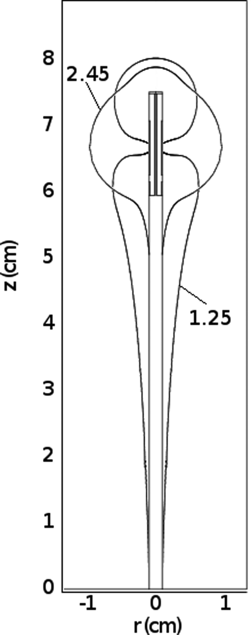
Comparison of heating patterns created by a dual-slot antenna at 1.25 and 2.45 GHz. Despite low reflections of −20 dB at each frequency, the antenna only produces the desired heating pattern at 2.45 GHz.
Antenna insertion depth had little effect on the dual-slot design at 2.45 GHz (Fig. 8). When considering ±30% variations in the relative permittivity of the tissue medium, both dual-slot and monopole reflection coefficients remained below −13 dB at 2.45 GHz (Fig. 9). The mean percent difference in reflection coefficient at baseline and varied permittivities was 1.96% for the dual-slot design and 0.06% for the monopole. In experimental studies, the mean reflection coefficient prior to ablation was similar for both dual-slot and monopole antennas but was slightly higher for the dual-slot design after the ablation. This difference was not statistically or practically significant (Table TABLE II.).
Figure 8.

Comparison of reflection coefficients and normalized SAR for the dual-slot antenna at three depths of insertion: 20, 40, and 60 mm. The air-tissue interface lies at z = 10 mm. Reflections were relatively unaffected by insertion depth at 2.45 GHz due to the truncated heating pattern, but more substantial variations were noted at 0.5–1.5 GHz due to the elongated heating at those frequencies.
Figure 9.

Simulated reflection coefficient of the dual-slot antenna for baseline liver tissue (0%) and changes in relative permittivity of ±10, ±20, and ±30%. At 2.45 GHz the reflection coefficient ranges from −24 dB to −13 dB. There was virtually no change in reflection coefficient at 1.6 GHz.
TABLE II.
Ablation zone dimensions and reflection coefficients created by dual-slot and monopole antennas in ex vivo bovine liver. Data presented as mean ± standard deviation. NS indicates no statistically significant difference.
| Time (min) | Diameter (mm) | Length (mm) | Aspect ratio | G (initial) (dB) | G (final) (dB) | G (Time-average) (dB) | |
|---|---|---|---|---|---|---|---|
| Dual-slot | 2 | 19.1 ± 0.9 | 26.9 ± 1.7 | 0.711 ± 0.01 | −18.9 ± 5.9 | −12.5 ± 2.4 | −15.7 ± 3.4 |
| 5 | 25.7 ± 1.6 | 37.6 ± 1.4 | 0.683 ± 0.05 | −19.1 ± 4.1 | −10.2 ± 2.4 | −14.7 ± 2.8 | |
| 10 | 34.7 ± 2.4 | 49.2 ± 2.1 | 0.706 ± 0.03 | −19.2 ± 9.2 | −09.2 ± 2.1 | −14.2 ± 5.6 | |
| Monopole | 2 | 16.4 ± 1.5 | 31.6 ± 4.3 | 0.528 ± 0.08 | −17.9 ± 5.6 | −21.2 ± 9.8 | −19.6 ± 5.1 |
| 5 | 23.4 ± 2.0 | 46.0 ± 3.9 | 0.513 ± 0.07 | −19.7 ± 1.7 | −14.2 ± 5.4 | −16.9 ± 2.0 | |
| 10 | 31.1 ± 2.1 | 59.6 ± 6.3 | 0.527 ± 0.06 | −20.2 ± 5.4 | −12.1 ± 4.3 | 16.1 ± 2.3 | |
| Dual-slot v. | 2 | NS | NS | <0.001 | NS | NS | NS |
| Monopole | 5 | NS | <0.01 | <0.001 | NS | NS | NS |
| P-values | 10 | <0.05 | <0.001 | <0.001 | NS | NS | NS |
In simulations, the most optimal dual-slot design produced slightly larger ablation diameters and substantially shorter ablation lengths than the monopole. This trend was confirmed experimentally, where ablations produced by the dual-slot design were 2–3 mm greater in diameter, and 5–10 mm shorter, than those produced by the monopole antenna (Fig. 10, Table TABLE II.). As a result, the ablation aspect ratio produced by the dual-slot design was significantly greater (P < 0.001, all times). Dual-slot ablations developed a slight tail along the antenna shaft which was distinguishable from the elongated overall shape observed with monopole ablations (Fig. 11).
Figure 10.

Mean diameters and lengths of ablations created by the optimal dual-slot (black∕square) and monopole (gray∕diamond) antennas. Simulations are represented by dashed lines, experiments by symbols. The 50 °C isotherm defined the ablation boundary in simulations. Bars represent the standard error of the mean in experimental data.
Figure 11.

Ablations created by the optimal dual-slot (left) and monopole (right) antennas in ex vivo bovine liver. Both images presented at equal scale. A total of 50 W at 2.45 GHz was delivered for 10 min in each case. Overall, dual-slot ablations were shorter in length and larger in diameter than monopole ablations.
DISCUSSION
This study presented the design and experimental validation of a dual-slot antenna for microwave ablation. Design was accomplished by numerical simulation and parametric analysis of the antenna geometry. The most optimal design produced a reflection coefficient of −20.9 dB and heating aspect ratio of 0.7 at the operating frequency of 2.45 GHz. Experimental data supported numerical results in demonstrating that the dual-slot design was able to increase ablation zone diameter and decrease ablation zone length when compared to a conventional monopole antenna.
The distal slot and tip identified in the parametric analysis create a loaded quarter-wave monopole without a grounding plane. Alone, this structure would provide reasonably efficient radiation, but also an elongated ablation zone. The proximal slot counteracts this negative result. The phase of currents from the proximal and distal slots destructively interferes at the mid-point of the separation length and along the antenna shaft to create an active choke that truncates the heating pattern. In this way, the separation length may be viewed as a resonant dipole with two separate feed points which are phase adjusted. Removing the end cap or substantially altering the antenna geometry destroyed the beneficial phase relationship, resulting in longer heating patterns or less efficient radiation. The choking effect is accomplished without adding to the antenna diameter, making this design well-suited for either open surgical or percutaneous applications.
The dual-slot design in this paper roughly resembles the morphology of slotted antennas previously presented in the literature.12, 13, 14, 15, 16, 17, 18, 19, 20, 21, 22, 23, 24, 25, 26, 27, 28, 29 However, previous studies have considered a fixed antenna geometry based on a 10 mm short-circuited stub and 1 mm slot width. Little focus has been given to the balance between reflection coefficient and antenna heating pattern. In this study, design criteria reflected a clinical perspective. The clinical goal of a highly spherical ablation zone was weighted equally with electromagnetic considerations such as efficient radiation in the objective function. The resulting antenna geometry is, therefore, functionally unique from previous designs.
Previous studies have also considered design sensitivity to the intended tissue environment.30, 31 While microwave tumor ablation has historically been performed most frequently in the liver, it is emerging as a treatment option for tumors in the kidney, lung, and bone as well. The properties of normal kidney are similar to liver, but normal lung and bone are characterized by very different relative permittivity and effective conductivity values. Similar variability is encountered in tissues with altered pathology, such as diseased organs or tumors. The dual-slot design considered in this work appears to tolerate variations in the tissue properties for which the antenna was originally designed. Design optimization for other organ structures may also be possible, such as tumors in the adrenal glands, pancreas, neck, or brain. It should also be recognized that a spherical ablation zone may not be ideal for all clinical needs. For example, elongated heating patterns might be more preferable in some applications such as cardiac ablation, surgical hemostatis, ablation-assisted organ resection, or endolumenal approaches. More oblate heating patterns may also be beneficial when using multiple applicators in concert to treat spherical tumors. Additional study is needed to define the optimal heating pattern for each clinical scenario.
Single applicators have historically been applied to tumors less than about 2 cm in diameter; those larger than 3 cm typically required multiple applicators or multiple overlapping ablations to cover the tumor plus an ablative margin.32 Devices capable of creating larger ablation zones increase the feasibility of treating tumors 2–4 cm in diameter with a single applicator. The need for effective single-applicator devices is especially true in many centers that are averse to the cost of using multiple applicators. The clinical need for spherical ablation zones also extends into tumors which abut the body wall or which lie near critical structures such as the diaphragm, important vasculature, bile ducts, bronchi, or the renal collecting system. In these cases, an elongated ablation may limit the degree of freedom during applicator placement or preclude the use of a percutaneous approach entirely. A controlled, spherical ablation zone would reduce such constraints on placement.
Certain limitations in this study will need to be addressed in the future. The present design was constrained to allow only two slots, with a distal slot abutting the end cap. A generalized optimization of coaxial slot geometries may reveal other suitable designs. The most optimal design was also identified using parametric analysis, rather than a true optimization approach. Parametric analysis was employed to allow the possibility of multiple cost function minima in the parametric space and analyze the effect of geometry variations more completely. Through this approach, a 1-mm tolerance in distal slot width and separation length was identified. However, optimization with quasi-Newtonian, simplex, genetic, or Bayesian algorithms may be helpful in future studies.
We also acknowledge that experimental results were obtained at only one power level in an ex vivo tissue model. Further studies utilizing in vivo models will be able to more completely evaluate the dual-slot design for clinical microwave ablation. For example, the slight tail noted in ex vivo ablations may be partially due to internal heating in the coaxial cable used to fabricate the experimental antennas. In vivo blood flow or an effective cooling system along the antenna shaft would likely reduce or eliminate this tail completely.33
In conclusion, parametric analysis of a dual-slot antenna revealed that both the antenna reflection coefficient and spatial heating profile are highly sensitive to antenna geometry. A two-term sigmoidal cost function including both reflection coefficient and heating aspect ratio identified the most optimal design. When applied to ex vivo tissue, the dual-slot antenna efficiently coupled energy into the tissue and created ablation zones that were relatively spherical in shape. The feasible operating bandwidth spanned over 1 GHz, indicating the potential to be applied in several tissue environments. However, antenna heating pattern was noted to change with frequency. Focal heating was accomplished without the addition of passive chokes, so the antenna diameter remained small enough for percutaneous applications. Further exploration of this antenna design for clinical microwave ablation appears warranted.
TABLE III.
Top ten simulated designs by reflection coefficient, with relevant performance data. Diameter, length, and aspect ratio are measured from the SAR = 30 W∕kg isocontour. Many of these designs produced very elongated heating patterns that would not be suitable for clinical use.
| Rank | G1 (mm) | L (mm) | G2 (mm) | Objective | S11 (dB) | Diameter (mm) | Length (mm) | Aspect Ratio |
|---|---|---|---|---|---|---|---|---|
| 1 | 8 | 20 | 10 | 0.999 | −30.7 | 14.5 | 71.9 | 0.20 |
| 2 | 1 | 8 | 3 | 0.644 | −27.8 | 19.8 | 30.1 | 0.66 |
| 3 | 2 | 8 | 2 | 0.947 | −27.2 | 19.3 | 38.1 | 0.51 |
| 4 | 7 | 20 | 10 | 1.000 | −25.3 | 14.2 | 72.7 | 0.20 |
| 5 | 1 | 7 | 2 | 0.853 | −25.0 | 19.5 | 33.5 | 0.58 |
| 6 | 8 | 19 | 10 | 1.000 | −24.3 | 14.4 | 71.9 | 0.20 |
| 7 | 9 | 20 | 9 | 1.000 | −24.1 | 14.5 | 71.3 | 0.20 |
| 8 | 9 | 19 | 10 | 1.000 | −23.8 | 14.8 | 71.3 | 0.21 |
| 9 | 8 | 20 | 9 | 1.001 | −22.8 | 14.3 | 72.5 | 0.20 |
| 10 | 1 | 8 | 2 | 0.827 | −22.6 | 18.9 | 31.7 | 0.60 |
TABLE IV.
Top ten simulated designs by heating zone aspect ratio, with relevant performance data. Diameter, length, and aspect ratio are measured from the SAR = 30 W∕kg isocontour. Several of these designs create reflection coefficients that would increase cable shaft heating and degrade performance in tissue.
| Rank | G1 (mm) | L (mm) | G2 (mm) | Objective | S11 (dB) | Diameter (mm) | Length (mm) | Aspect Ratio |
|---|---|---|---|---|---|---|---|---|
| 1 | 1 | 7 | 7 | 0.794 | −9.0 | 20.4 | 25.4 | 0.80 |
| 2 | 1 | 7 | 6 | 0.614 | −10.7 | 20.6 | 26.0 | 0.79 |
| 3 | 1 | 7 | 5 | 0.552 | −12.9 | 20.1 | 27.3 | 0.74 |
| 4 | 1 | 7 | 8 | 1.254 | −7.7 | 18.1 | 25.7 | 0.70 |
| 5 | 1 | 8 | 4 | 0.520 | −20.9 | 20.4 | 29.2 | 0.70 |
| 6 | 1 | 6 | 8 | 1.369 | −6.9 | 18.3 | 26.6 | 0.69 |
| 7 | 1 | 6 | 9 | 1.423 | −6.1 | 17.9 | 26.0 | 0.69 |
| 8 | 1 | 7 | 4 | 0.612 | −15.7 | 19.9 | 29.1 | 0.68 |
| 9 | 1 | 6 | 10 | 1.524 | −5.4 | 17.6 | 26.3 | 0.67 |
| 10 | 1 | 8 | 3 | 0.644 | −27.8 | 19.8 | 30.1 | 0.66 |
ACKNOWLEDGMENTS
This work was supported by the National Institutes of Health 1R01CA14273701. The author wishes to thank Luke Juckett for his assistance with experimental data collection and Jason Chiang for discussions related to this work. The author also wishes to disclose the following potential conflicts of interest: paid consultant, patent author, and shareholder with NeuWave Medical, Inc., Madison, WI.
Appendix: Design permutations ranked by reflection coefficient and heating aspect ratio
References
- Livraghi T., Meloni F., Di Stasi M., Rolle E., Solbiati L., Tinelli C., and Rossi S., “Sustained complete response and complications rates after radiofrequency ablation of very early hepatocellular carcinoma in cirrhosis: Is resection still the treatment of choice?” Hepatology 47, 82–89 (2008). 10.1002/hep.21933 [DOI] [PubMed] [Google Scholar]
- Gervais D. A., McGovern F. J., Arellano R. S., McDougal W. S., and Mueller P. R., “Radiofrequency ablation of renal cell carcinoma: Part 1. Indications, results, and role in patient management over a 6-year period and ablation of 100 tumors,” AJR Am. J. Roentgenol. 185, 64–71 (2005). [DOI] [PubMed] [Google Scholar]
- Abbas G., Pennathur A., Landreneau R. J., and Luketich J. D., “Radiofrequency and microwave ablation of lung tumors,” J. Surg. Oncol, 100, 645–650 (2009). 10.1002/jso.v100:8 [DOI] [PubMed] [Google Scholar]
- Nikfarjam M., Muralidharan V., and Christophi C., “Mechanisms of focal heat destruction of liver tumors,” J. Surg. Res. 127, 208–223 (2005). 10.1016/j.jss.2005.02.009 [DOI] [PubMed] [Google Scholar]
- Andreano A., Huang Y., Meloni M. F., F.Lee T., and Brace C. L., “Microwaves create larger ablations than radiofrequency when controlled for power in ex vivo tissue,” Med. Phys. 37, 2967–2973 (2010). 10.1118/1.3432569 [DOI] [PMC free article] [PubMed] [Google Scholar]
- Wright A. S., L.Sampson A., Warner T. F., Mahvi D. M., and Lee F. T. J., “Radiofrequency versus microwave ablation in a hepatic porcine model,” Radiology 236, 132–139 (2005). 10.1148/radiol.2361031249 [DOI] [PubMed] [Google Scholar]
- Yu N. C., Raman S. S., Kim Y. J., Lassman C., Chang X., and Lu D. S. K., “Microwave liver ablation: influence of hepatic vein size on heat-sink effect in a porcine model,” J. Vasc. Interv. Radiol. 19, 1087–1092 (2008). 10.1016/j.jvir.2008.03.023 [DOI] [PubMed] [Google Scholar]
- Wolf F. J., Grand D. J., Machan J. T., Dipetrillo T. A., Mayo-Smith W. W., and Dupuy D. E., “Microwave ablation of lung malignancies: Effectiveness, CT findings, and safety in 50 patients,” Radiology 247, 871–879 (2008). 10.1148/radiol.2473070996 [DOI] [PubMed] [Google Scholar]
- Liang P., Wang Y., Yu X., and Dong B., “Malignant liver tumors: Treatment with percutaneous microwave ablation–complications among cohort of 1136 patients,” Radiology 251, 933–940 (2009). 10.1148/radiol.2513081740 [DOI] [PubMed] [Google Scholar]
- Labonte S., Blais A., Legault S., Ali H., and Roy L., “Monopole antennas for microwave catheter ablation,” IEEE Trans. Microwave Theory Tech. 44, 1832–1840 (1996). 10.1109/22.539941 [DOI] [Google Scholar]
- Hurter W., Reinbold F., and Lorenz W., “A dipole antenna for interstitial microwave hyperthermia,” IEEE Trans. Microwave Theory Tech. 39, 1048–1054 (1991). 10.1109/22.81680 [DOI] [Google Scholar]
- Ito K., Hyodo M., Shimura M., and Kasai H., “Thin applicator having coaxial ring slots for interstitial microwave hyperthermia,” Ant. Prop. Soc. Int. Sym. 3, 1233–1236 (1990). 10.1109/APS.1990.115335 [DOI] [Google Scholar]
- Brace C. L., Laeseke P. F., Van der Weide D. W., and Lee F. T., “Microwave ablation with a triaxial antenna: results in ex vivo bovine liver ,” IEEE Trans. Microwave Theory Tech. 53, 215–220 (2005). 10.1109/TMTT.2004.839308 [DOI] [PMC free article] [PubMed] [Google Scholar]
- Shock S. A., Meredith K., Warner T. F., Sampson L. A., Wright A. S., T. C.WinterIII, Mahvi D. M., Fine J. P., and Lee F. T. J., “Microwave ablation with loop antenna: In vivo porcine liver model,” Radiology 231, 143–149 (2004). 10.1148/radiol.2311021342 [DOI] [PubMed] [Google Scholar]
- Brace C. L., “Microwave ablation technology: What every user should know,” Curr. Probl. Diagn. Radiol. 38, 61–67 (2009). 10.1067/j.cpradiol.2007.08.011 [DOI] [PMC free article] [PubMed] [Google Scholar]
- Bertram J. M., Yang D., Converse M. C., Webster J. G., and Mahvi D. M., “A review of coaxial-based interstitial antennas for hepatic microwave ablation,” Crit. Rev. Biomed. Eng. 34, 187–213 (2006). [DOI] [PubMed] [Google Scholar]
- Lin J. C. and Wang Y. J., “The cap-choke catheter antenna for microwave ablation treatment,” IEEE Trans. Biomed. Eng. 43, 657–660 (1996). 10.1109/10.495286 [DOI] [PubMed] [Google Scholar]
- Longo I., Gentili G., Cerretelli M., and Tosoratti N., “A coaxial antenna awith miniaturized choke for minimally invasive interstitial heating,” IEEE Trans. Microwave Theory Tech. 50, 82–88 (2003). [DOI] [PubMed] [Google Scholar]
- Yang D., Bertram J. M., Converse M. C., ’Rourke A. P.O, Webster J. G., Hagness S. C., Will J. A., and Mahvi D. M., “A floating sleeve antenna yields localized hepatic microwave ablation,” IEEE Trans. Biomed. Eng. 53, 533–537 (2006). 10.1109/TBME.2005.869794 [DOI] [PubMed] [Google Scholar]
- Geraghty P. R., Kee S. T., McFarlane G., Razavi M. K., Sze D. Y., and Dake M. D., “CT-guided transthoracic needle aspiration biopsy of pulmonary nodules: Needle size and pneumothorax rate,” Radiology 229, 475–481 (2003). 10.1148/radiol.2291020499 [DOI] [PubMed] [Google Scholar]
- Saito K., Yoshimura H., Ito K., Aoyagi Y., and Horita H., “Clinical trials of interstitial microwave hyperthermia by use of coaxial-slot antenna with two slots,” IEEE Trans. Microwave Theory Tech. 52, 1987–1991 (2004). 10.1109/TMTT.2004.832005 [DOI] [Google Scholar]
- Converse M. C., Webster J. G., Mahvi D. M., and Peng Wang, “Improved calculation of reflection coefficient for coaxial antennas with feed gap effect,” Antennas and Propagation, IEEE Trans. 57, 559–563 (2009). 10.1109/TAP.2008.2011411 [DOI] [Google Scholar]
- Duck F. A., Physical Properties of Tissue: A Comprehensive Reference Book (Academic, London, 1990). [Google Scholar]
- Gabriel S., Lau R. W., and Gabriel C., “The dielectric properties of biological tissues: II. Measurements in the frequency range 10 Hz to 20 GHz,” Phys. Med. Biol. 41, 2251–2269 (1996). 10.1088/0031-9155/41/11/002 [DOI] [PubMed] [Google Scholar]
- Brace C. L., “Temperature-dependent dielectric properties of liver tissue measured during thermal ablation: Toward an improved numerical model,” Conf. Proc. IEEE Eng. Med. Biol. Soc. 2008, 230–233. 10.1109/IEMBS.2008.4649132 [DOI] [PubMed]
- ’Rourke A. P.O, Lazebnik M., Bertram J. M., Converse M. C., Hagness S. C., Webster J. G., and Mahvi D. M., “Dielectric properties of human normal, malignant and cirrhotic liver tissue: In vivo and ex vivo measurements from 0.5 to 20 GHz using a precision open-ended coaxial probe,” Phys. Med. Biol. 52, 4707–4719 (2007). 10.1088/0031-9155/52/15/022 [DOI] [PubMed] [Google Scholar]
- Saito K., Hayashi Y., Yoshimura H., and Ito K., “Heating characteristics of array applicator composed of two coaxial-slot antennas for microwave coagulation therapy,” IEEE Trans. Microwave Theory Tech. 48, 1800–1806 (2000). 10.1109/22.883857 [DOI] [Google Scholar]
- Saito K., Kikuchi S., Hiroe A., Takahashi M., and Ito K., “Numerical calculations of heating patterns around a coaxial-slot antenna for microwave hyperthermia - aiming at treatment of brain tumor and bile duct carcinoma,” Conf. Proc. IEEE Eng. Med. Biol. Soc. 1, 478–481 (2005). 10.1109/IEMBS.2005.1616451 [DOI] [PubMed] [Google Scholar]
- Hamada L., Saito K., Yoshimura H., and Ito K., “Dielectric-loaded coaxial-slot antenna for interstitial microwave hyperthermia: Longitudinal control of heating patterns,” Int. J. Hyperthermia 16, 219–229 (2000). 10.1080/026567300285240 [DOI] [PubMed] [Google Scholar]
- Durick N. A., Laeseke P. F., Broderick L. S., Lee F. T., Sampson L. A., Frey T. M., Warner T. F., Fine J. P., Van der Weide D. W., and Brace C. L., “Microwave ablation with triaxial antennas tuned for lung: results in an in vivo porcine model,” Radiology 247, 80–87 (2008). 10.1148/radiol.2471062123 [DOI] [PubMed] [Google Scholar]
- Prakash P., Deng G., Converse M. C., Webster J. G., Mahvi D. M., and Ferris M. C., “Design optimization of a robust sleeve antenna for hepatic microwave ablation,” Phys. Med. Biol. 53, 1057–1069 (2008). 10.1088/0031-9155/53/4/016 [DOI] [PubMed] [Google Scholar]
- G. D.DoddIII, Frank M. S., Aribandi M., Chopra S., and Chintapalli K. N., “Radiofrequency thermal ablation: computer analysis of the size of the thermal injury created by overlapping ablations,” AJR Am. J. Roentgenol. 177, 777–782 (2001). [DOI] [PubMed] [Google Scholar]
- Kuang M., Lu M. D., Xie X. Y., Xu H. X., Mo L. Q., Liu G. J., Xu Z. F., Zheng Y. L., and Liang J. Y., “Liver cancer: Increased microwave delivery to ablation zone with cooled-shaft antenna–experimental and clinical studies,” Radiology 242, 914–924 (2007). 10.1148/radiol.2423052028 [DOI] [PubMed] [Google Scholar]