Abstract
A novel neutron microbeam is being developed at the Radiological Research Accelerator Facility (RARAF) of Columbia University. The RARAF microbeam facility has been used for studies of radiation bystander effects in mammalian cells for many years. Now a prototype neutron microbeam is being developed that can be used for bystander effect studies. The neutron microbeam design here is based on the existing charged particle microbeam technology at the RARAF. The principle of the neutron microbeam is to use the proton beam with a micrometre-sized diameter impinging on a very thin lithium fluoride target system. From the kinematics of the 7Li(p,n)7Be reaction near the threshold of 1.881 MeV, the neutron beam is confined within a narrow, forward solid angle. Calculations show that the neutron spot using a target with a 17-µm thick gold backing foil will be <20 µm in diameter for cells attached to a 3.8-µm thick propylene-bottomed cell dish in contact with the target backing. The neutron flux will roughly be 2000 per second based on the current beam setup at the RARAF singleton accelerator. The dose rate will be about 200 mGy min−1. The principle of this neutron microbeam system has been preliminarily tested at the RARAF using a collimated proton beam. The imaging of the neutron beam was performed using novel fluorescent nuclear track detector technology based on Mg-doped luminescent aluminum oxide single crystals and confocal laser scanning fluorescent microscopy.
INTRODUCTION
Among the many compelling reasons to study radiation effects due to low-energy neutron radiation, a primary reason is because a significant number of individuals are occupationally exposed to low doses of neutrons, mostly low-energy neutrons (<50 keV). For example, about 4000 individuals obtained measurable neutron doses at the US Department of Energy facilities during 2003(1). In addition, about 6000 Nuclear Regulatory Commission-monitored workers per year (research workers, well loggers and reactor workers) receive measurable neutron doses(2). The neutron energy spectrum to which such individuals will be exposed varies widely, depending on the neutron source and the degree of moderation applied to the neutrons. Considering the kerma-weighted fluences at a location where personnel are potentially exposed in a commercial nuclear reactor, the important neutron energy range in terms of dose deposition is, on average, from about 10–100 keV(3). Additionally, neutron-induced radiation bystander effects may well dominate the extrapolation of measured radiation risk to very low doses. Because the primary energy damage patterns are so different, there is no a priori way of knowing whether the bystander mechanisms that have been extensively studied with charged particles and photons will be similar, quantitatively or qualitatively, to those for neutrons. To study human exposure to low-energy neutrons (especially those with energies 10–100 keV) and to explore the mechanism of neutron-induced bystander effects, a neutron microbeam system is being developed based on existing microbeam techniques at the Radiological Research Accelerator Facility (RARAF) of Columbia University.
NEUTRON MICROBEAM DESIGN
The principle of the neutron microbeam
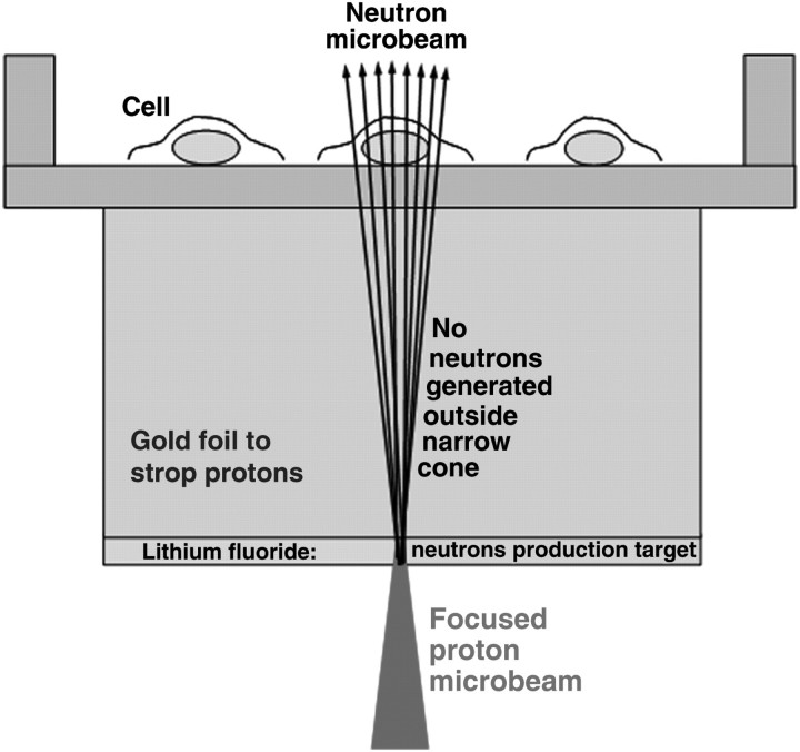
The 7Li(p,n)7Be nuclear reaction, which has a threshold at 1.881 MeV, is a well-known source for generating neutrons. The near-threshold reaction provides a relatively high neutron yield, as well as a very narrow forwardly peaked angular distribution for the outgoing neutrons(4). The narrow forward-peaked neutron microbeam results from the fact that the velocity of the centre of mass is greater than the outgoing velocity of the neutrons. As shown, this ‘kinematic collimation’ enables one to produce neutron microbeams with diameters of <20 µm, starting with a proton microbeam with a diameter of 5 µm. A schematic of the neutron microbeam single-cell irradiation experiment setup is shown in Figure 1. An electrostatic double-triplet lens system is used to focus the incoming proton beam onto a lithium fluoride layer on a thin gold backing foil. The proton beam will be stopped by the backing foil, but the forward neutron beam will pass through the backing foil and irradiate the cells. The backing foil will also serve as the system vacuum window. The geometry of the microbeam system requires the source-to-sample distance to be very small. Assuming a 1-µm thick LiF target layer with a 17-µm thick backing foil (Figure 1) and an additional 3 µm for the thickness of the cell dish bottom, the total distance from the target to the cells is about 20 µm.
Figure 1.
A schematic of the neutron microbeam experiment.
Table 1 lists the calculated neutron yields and dose rates near the reaction threshold. The calculations are based on a 10 nA proton beam, which is typically obtained. Maintaining the neutron microbeam spot size generated from a 5-µm diameter proton beam in the range from 8 to 18 µm will require a proton beam energy between 1.882 and 1.886 MeV. It is clear that the key to the neutron microbeam design is the extremely high-energy stability of the new Singletron accelerator (∼1 keV) here.
Table 1.
Calculated neutron microbeam performance parameters.
| Proton energy (MeV) | Neutron yield (per nC) | Maximum neutron angle (degrees) | Neutron beam diameter (µm) | Mean neutron energy (keV) | Dose rate (mGy min−1) |
|---|---|---|---|---|---|
| 1.882 | 270 | 9 | 8.1 | 30.0 | 80 |
| 1.883 | 800 | 13 | 10.5 | 30.2 | 140 |
| 1.884 | 1440 | 16 | 12.5 | 30.5 | 180 |
| 1.885 | 2230 | 19 | 14.7 | 30.7 | 200 |
| 1.886 | 3170 | 21 | 16.2 | 31.0 | 230 |
Within a 20° forward angle, the generated neutrons have an energy range of 10–50 keV. The neutron yield from protons impinging on the lithium fluoride target design is about 2000 per nC. In this case, the flux is about 5 neutrons µm−2 s−1. Based on kerma factors from Bach and Caswell(5), the predicted dose rates for the different diameter neutron microbeams are shown in Table 1 and also discussed in a later section.
Backing foil of neutron microbeam
The lithium fluoride-plated backing foil is critical because it must stop all the protons. As well, significant temperature increases in the backing foil material will compromise the target coating as well as damage the cells to be irradiated. The Monte Carlo code SRIM was used to simulate the proton transport and ionisation process in the LiF/Au layer. To satisfy the microbeam requirement and to absorb all of the protons, a 17-µm thick gold foil is required. Need to note, for keV energy neutrons, the scattering in this thin gold foil is negligible (about 10−4). Based on the specific heat capacity and the thermal conductivity of the target backing, the rate of temperature change in the target can simply be calculated. Gold is the best candidate for the backing foil because it has high thermal conductivity. From the calculations, the temperature differential on the gold backing foil is only 0.50° K for a 1 nA, 1.9 MeV proton beam, when the diameter of the backing foil.increases from 5 µm to 10 mm,
Dose rate of neutron microbeam
The generated neutrons have an energy range from 10 keV to 50 keV which is based on the near-threshold proton energy. The neutron yield from protons impinging on a lithium fluoride target is about 100–200 per second per nA of proton current (3–6 neutrons µm−2 s−1) and, when using a pure lithium target, the yield is increased to about three times that amount. But a pure lithium target is not easy for practical application.
The kerma factors for 10 keV and 50 keV neutrons from Bach and Caswell(5) are 0.096 and 0.394×10⁻¹¹ Gy cm2. So, if one assumes a beam with 50 % 10 keV-energy neutrons and 50 % 5-keV energy neutrons, the dose rate will be in the range of 80–230 mGy min−1 for a 10-nA proton beam impinging on an LiF target. For the low-energy proton-induced X-rays of gold, The L shell X-ray is about 13 keV(6), which is negligible on the far side of the gold backing foil. The K shell X-rays are with energies about 60–80 keV have much lower production cross section than the L shell X-rays(7, 8) and can be ignored also. The major background dose from an LiF target is due to 478 keV gamma rays from the 7Li(p,p′γ) reaction, 109- and 197-keV gamma rays from the 19F(p,p′γ) reaction and 6-MeV gamma rays from 19F(p,αγ)16O reaction. The kerma factor for 478-keV photons is about 0.2×10⁻¹¹ Gy cm2(9). It is about a factor of 2 larger than for 10-keV neutrons and about one-half that for 50-keV neutrons. The overall ratio is about 1. The 478-keV gamma ray yield from 1.89-MeV protons is about 25 times higher than the neutron yield(10), however, neutrons are produced within a very small solid angle, which is about one-hundredth that for the photons (4π). Considering the geometry, the 478-keV gamma ray dose is only about 25 % of the neutron dose. And it is much less in terms of equivalent dose (∼1.6 %)(11). For the 19F(p,p′γ) reaction, the total cross sections of 110 and 197 keV gamma ray are about same as the cross section of the 478-keV gamma ray from 7Li(p,p′γ) reaction(12, 13). But the kerma factors for the two gamma rays are roughly about 25 % of that for the 478-keV gamma ray. So the total contribution of gamma background from 19F(p,p′γ) reaction will be half the contribution from the 7Li(p,p′γ) reaction, which is about 12.5 % of the neutron dose and 0.8 % of the neutron equivalent dose.
The 19F(p,αγ) reaction, which produces ∼6-MeV gamma rays, has a relatively lower cross section (∼1/6 of 197-keV gamma ray cross section of the 19F(p,p′γ) reaction)(14) and even with a kerma factor eight times higher, it will only give about 60 % of total contribution from 19F(p,p′γ) reaction. By controlling the target thickness to the minimum necessary, the production of resonance gamma rays in the thin target will be limited.
THE CONCEPT TEST
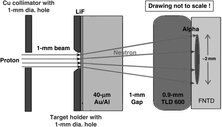
The first concept measurement was conducted using a beam collimator system at the RARAF (Figure 2). To implement the setup on the proton microbeam system here, a lithium fluoride target was custom designed and installed. The system included a target holder with a 1-mm diameter hole and a thin LiF foil on a 40-µm thick Au/Al backing foil. As mentioned earlier, the LiF foil will only produce about on-third of the neutron yield as a pure lithium target will. However, LiF is significantly easier to handle during the development work here. The gold backing foil was glued onto a brass holder with a 1-mm diameter centre hole in it and mounted onto a microbeam port. The LiF coating was evaporated on the gold film positioned behind the 1-mm diameter hole in the mask.
Figure 2.
A schematic of measurement setup for mapping of neutron field.
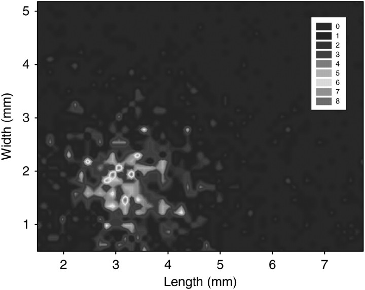
The proton beam was collimated by a copper disc with a 1-mm diameter aperture in the middle. The initial proton beam was stopped in the gold backing foil but the neutron beam, with more penetration ability, passed through. The imaging of the neutron beam was performed using novel fluorescent nuclear track detector technology (FNTD)(15, 16). The technology is based on Mg-doped aluminum oxide single crystal plates and confocal laser scanning fluorescent microscopy. Aluminum oxide detectors are not directly sensitive to neutrons and have to be covered by a converter material. For low-energy neutrons produced in the described experiments, converters made of 0.9-mm thick LiF chips enriched with 6Li isotope (TLD600) were used. Nuclear reaction 6Li(n,α) generates an alpha particle and a tritium ion which in turn produce fluorescent tracks in aluminum oxide FNTD detector. High-resolution imaging technique allows imaging, identification, counting of individual tracks and mapping of the neutron field through the calculated track densities (Figure 3). The intensity of each pixel on the map of Figure 3 corresponds to a track density obtained from one 100×100 μm fluorescent image. To increase the resolution of neutron field mapping one can use thinner 6Li converters and fluorescent images as small as 5×5 μm. Based on the geometry of the described system, the 1.5 mm diameter of the beam size was predicted and measured.
Figure 3.
Map of a neutron microbeam obtained by measuring track densities in aluminum oxide fluorescent nuclear track detector.
FUNDING
This work was supported by the National Institute of Biomedical Imaging and Bioengineering (NIBIB grant #8P41EB002033).
REFERENCES
- 1.The U.S. Department of Energy (DOE) Office of Corporate Performance Assessment (EH-3) 2004. DOE Occupational Radiation Exposure—2003 Report. DOE/EH-0688, Science Applications International Corporation.
- 2.Endres G. W. R., Aldrich J. M., Brackenbush L. W., Faust L. G., Griffith R. V., Hankins D. E. Neutron Dosimetry at Commercial Nuclear Plants. 1981. US Nuclear Regulatory Commission Report NUREG/CR-1769 (Pacific Northwest Laboratory PNL-3585), Science Applications International Corporation.
- 3.Nuclear Regulatory Commission. Occupational Radiation Exposure at Commercial Nuclear Power Reactors and Other Facilities 1985. 1988. Eighteenth Annual Report, US Nuclear Regulatory Commission NUREG-0713, Science Applications International Corporation.
- 4.Lee C. L., Zhou X. L. Thick target neutron yields for the Li-7(p,n)Be-7 reaction near threshold. Nucl. Instrum. Methods B. 1999;152(1):1–11. [Google Scholar]
- 5.Bach R. L., Caswell R. S. Energy transfer to matter by neutrons. Radiat. Res. 1968;35(1):1–25. [PubMed] [Google Scholar]
- 6.Shafroth S. M., Bissinger G. A. Gold L x-ray production by 0.5-30 MeV protons. Phys. Rev. A. 1973;7(2):566–571. [Google Scholar]
- 7.Hyun J. C., Hyoung C. B., Baik-Nung S., Jong C. K. K-shell ionization cross sections for proton induced x-ray emissions. J. Korean Phys. Soc. 1988;21(1):130–138. [Google Scholar]
- 8.Hansteen J. M., Huseby O. K., Kocbach L. K-shell, ‘ionization induced by slow proton and antiproton impact. J. Phys. B At. Mol. Opt. Phys. 1993;26:L607. [Google Scholar]
- 9.Egbert S. D., Kerr G. D., Cullings H. M. DS02 fluence spectra for neutrons and gamma rays at Hiroshima and Nagasaki with fluence-to-kerma coefficients and transmission factors for sample measurements. Radiat. Environ. Biophys. 2007;46(4):311–325. doi: 10.1007/s00411-007-0120-5. [DOI] [PubMed] [Google Scholar]
- 10.Lee C. L., Zhou X. L., Kudchadker R. J., Harmon F., Harker Y. D. A Monte Carlo dosimetry-based evaluation of the 7Li(p,n)7Be reaction near threshold for accelerator boron neutron capture therapy. Med. Phys. 2000;27(1):192–202. doi: 10.1118/1.598884. [DOI] [PubMed] [Google Scholar]
- 11.Schmid E., Schlegel D., Guldbakke S., Kapsch R. P., Regulla D. RBE of nearly monoenergetic neutrons at energies of 36 keV-14.6 MeV for induction of dicentrics in human lymphocytes. Radiat. Environ. Biophys. 2003;42(2):87–94. doi: 10.1007/s00411-003-0200-0. [DOI] [PubMed] [Google Scholar]
- 12.Jesus A. P., Braizinha B., Ribeiro J. P. Excitation function and cross-sections of the reaction 19F(p,p0c)19F. Nucl. Instrum. Methods B. 2000;161–163:186. [Google Scholar]
- 13.Boni C., Cereda E., Braga-Marcazzan G. M., De Tomasi V. Prompt gamma emission excitation functions for PIGE analysis of Li, B, F, Mg, Al, Si and P in thin samples. Nucl. Instrum. Methods B. 1988;35:80. [Google Scholar]
- 14.Ranken W. A., Bonner T. W., McCrary J. H. Energy dependence of F19+p reactions. Phys. Rev. 1958;109:1646–1651. [Google Scholar]
- 15.Akselrod G. M., Akselrod M. S., Benton E. R., Yasuda N. A novel Al2O3 fluorescent nuclear track detector for heavy charged particles and neutrons. Nucl. Instrum. Methods B. 2006;247:296–306. [Google Scholar]
- 16.Sykora G. J., Salasky M., Akselrod M. S. Properties of novel fluorescent nuclear track detectors for use in passive neutron dosimetry. Radiat. Meas. 2008;43:1017–1023. doi: 10.1093/rpd/ncm058. [DOI] [PubMed] [Google Scholar]


