Abstract
A bi-directional neural interface (NI) system was designed and built by incorporating a novel neural recording and processing subsystem into a commercially approved neural stimulator. The NI system prototype leverages the system infrastructure from a market-approved neurostimulator to ensure reliable operation in a chronic implantation environment. In addition to providing approved therapy capabilities, the device adds key elements to facilitate chronic clinical research, such as four channels of ECoG/LFP amplification and spectral analysis, a three axis accelerometer, algorithm processing, event-based data logging, and wireless telemetry for data uploads and algorithm/configuration updates. The custom integrated micropower sensor and interface circuits facilitate extended operation in a power-limited device. The prototype underwent significant verification testing to ensure reliability, and meets the requirements for a class CF instrument per IEC-60601 protocols. The ability of the device system to process and aid in classifying brain states was preclinically validated using an in-vivo non-human primate model for brain control of a computer cursor (i.e., brain machine interface or BMI). The primate BMI model was chosen for its ability to quantitatively measure signal decoding performance from brain activity that is similar in both amplitude and spectral content to other biomarkers used to detect disease states (e.g. Parkinson’s). A key goal of this research prototype is to help broaden the clinical scope and acceptance of NI techniques, particularly real-time brain state detection. These techniques can be generalized beyond motor prosthesis, to include significant unmet needs in other neurological conditions such as movement disorders, stroke, and epilepsy.
I. Introduction
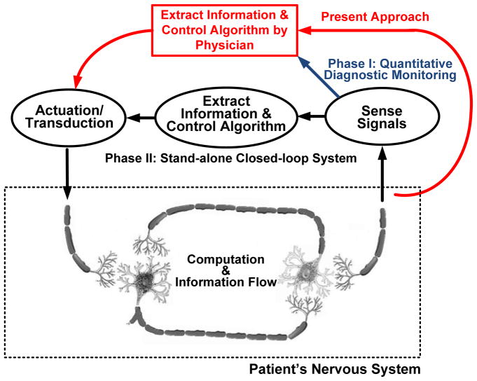
A fundamental problem in the treatment of neurological disease is determining when and how the disease is affecting the patient. This issue is demonstrated by existing treatments such as deep brain stimulation for Parkinson’s disease, essential tremor, and dystonia, which operate without sensing or interpreting a patient’s state (i.e., in “open-loop” mode). As illustrated in Fig. 1, in the absence of this embedded capability the sensing and titration algorithms are essentially performed through either direct observation and programming by a clinician or by limited patient intervention. Visibility into potentially useful neurological information derived from the electrodes is limited to an acute setting in which leads are externalized. This restricted access limits the observation of biomarkers that might be useful for therapy optimization [1][2][3].
Fig. 1.
Abstracted therapy control loops in a bi-directional neural interface.
The ability to chronically sense, process, and telemeter signals from the nervous system might help address these unmet needs and create new clinical applications in the future. This could lead to improved monitoring of disease progression and therapy efficacy in applications as diverse as movement disorders, epilepsy, and psychological disorders [10]. As understanding of neural dynamics improves, embedded sensors and chronic signal classification might also help optimize and deliver therapy in real-time (i.e., in a closed-loop mode). This could result in a decrease in the effort required from the clinician and patient to optimize the therapy, improved longevity of implantable devices with adaptive titration, and improved patient outcomes with therapy tied to quantitative physiological markers. Significant unmet needs of current interest include:
sensing the on and off states of Parkinson’s disease for potential stimulation therapy titration and using biomarker localization to guide optimal electrode selection[1][2][3],
burden monitors that can detect or predict the onset of seizures[4][5][6], and
assistive interfaces that could allow for direct translation of motor intentions to drive externalized controllers for physically impaired patients [7][8][9] or provide internal control signals for an implantable system.
The neural interface technology (NIT) required for deriving brain state information directly from neural signals is embodied in brain-machine interfacing (BMI). BMI is typically defined as a system that senses and decodes a subject’s intentions, usually in the context of motor control. Bidirectional BMI includes a means to provide feedback to the nervous system, such as stimulation of sensory afferents to provide bi-directional information flow in the nervous system. It has been explored for the last several decades, but has yet to be clinically adopted.
While the clinical opportunities for sensing and processing with NIT, like BMI, are relatively clear, significant practical hurdles have kept this technology from translating into a clinical setting. These include both the hurdles of deploying BMI as a standalone technology for applications like motor prosthesis, as well as adoption of closed-loop methodologies with sensing capabilities for existing therapy systems.
Foremost among the hurdles for stand-alone BMI deployment are the substantial development and clinical trial costs of developing such a device for human use. Medical devices require design innovation and verification overhead, substantial manufacturing infrastructure, regulatory oversight, and a clinical deployment strategy. For instance, while BMI prosthesis systems have shown promising results in small preclinical experiments [11] the practical issues associated with chronic deployment such as implantation technique, reliability of components, chronic signal integrity, and power consumption remain largely unaddressed [14]. In addition, clinical translation to the field requires rigorous use validation, not only to ensure that the device solves relevant clinical problems and does not interfere with existing therapy delivery, but also that it functions reliably in a diverse set of real-world environments such as surgical electrocautery, passing through metal detectors, and electrostatic discharge.
The hurdle of adding neural sensing technologies to existing therapy devices arise largely from the fact that the biomarkers of disease states are not currently well established and algorithms to appropriately titrate stimulation are therefore still being defined. Further exacerbating this is the fact that many neurological diseases are chronic and do not have adequate animal models so that chronic human data is needed to obtain the data to perform research and improve treatments. In addition, neural-sensing interfaces might not be sufficient to achieve adequate specificity. The monitoring of complementary information such as movement and posture might be required. Some promising discoveries related to deep brain stimulation (DBS) have been made in an acute setting [1][2][3][11][12][13]. But in order to fully understand the opportunity and limitations of sensor-based systems, a chronic method of collecting data must be provided to clinical researchers to help clarify the signals correlated with disease dynamics. This information can then serve to bridge the clinical translation of BMI technologies into broader applications.
This paper provides an overview of a bi-directional, NI prototype’s preclinical hardware design, verification, and validation. The design is meant to provide a bridge for exploring bidirectional BMI technologies in the broader scope of treating neurological disease, while at the same time providing a practical pathway for clinical BMI deployment by building on the capabilities of an existing therapy device. Section II provides the device requirements and describes the design of the system, with an emphasis on the sensing and algorithmic infrastructure’s generalization to a broad class of neurological applications. Section III presents a summary of the design and bench verification used to test the device for safety and functionality. Section IV provides details on the validation of the recording subsystem using a real-time BMI derived from epidural ECoG in a non-human primate. The intent is to demonstrate the device’s feasibility for clinically relevant applications, both for prosthesis and broader neurological applications. The validation methodology provides quantitative metrics for comparing our device’s performance against typical laboratory instrumentation that serves as the control. Section V provides a discussion of the design and results within a broader clinical perspective. Section VI provides this paper’s conclusion.
II. Implantable Bi-directional Neural Interface System Design
A. Motivation for and Overview of Design Requirements
1) Stimulation Requirements for the Interface Equivalency to Predicate Designs
A core motivation for the design of this system is to provide a strong predicate of clinically-relevant functionality and reliability in order to increase clinical acceptance. To achieve this goal, we established a requirement that the existing therapy stimulation capability of the ActivaPC™, which includes using approved electrodes in specific neural targets with the appropriate stimulation parameters for providing effective therapy, was fully replicated in this design. In addition to maintenance of stimulation circuitry and control, this requirement forced us to carefully design the microvolt neural interface to be compatible with active stimulation, including minimized cross-channel coupling. We also required that the hardware and firmware architecture use a multi-core partition that allows for the BMI-interface and accelerometer to run independently of the primary stimulation controller. This partition provides a firewall to prevent inadvertent malfunction of the predicate neurostimulator due to the addition of sensor processing. Longevity and reliability requirements for previous-generation designs also were transferred to this design, which motivated the creation of custom interface circuitry to meet requirements. Additional details on the effects of these design requirements will be discussed in the next sections.
2) Sensing Requirements of the Interface: Local Field Potentials and ECoG
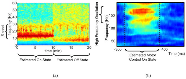
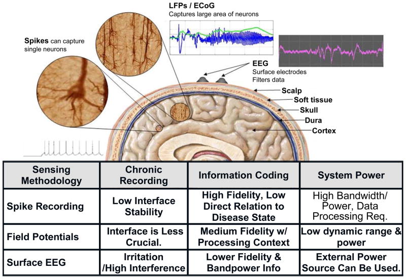
One of the critical design questions in determining brain state from neural activity is to find the appropriate scale to measure the neural activity. Neural activity can be measured using a number of techniques, ranging in resolution from single cell recording to the measurement of gross cortical activity with the electroencephalogram (EEG). LFPs and ECoG are intermediate resolution techniques that represent the ensemble activity of functional cellular networks in an in vivo neural population. From a scientific and clinical perspective, LFPs and ECoG appear to encode the key information on the functional neuronal networks that are correlated with disease symptoms [1]. This signal reflects neural network problems of many diseases, which yields different information than observing only single-cell signals. A common theme for several neurological disorders is that biomarkers are believed to be encoded in local field potentials (LFPs) as distinct fluctuations in the spectral content of the signal [1][18]. For example, Fig. 2a shows a spectrogram of LFP data collected from a Parkinson’s patient’s deep brain stimulation (DBS) leads recorded in an acute clinical setting [1]. The spectrogram demonstrates a high correlation between energy in the beta band and the pathological symptoms associated with the disorder as well as with changes in treatment. Similar spectral signatures are seen for standard cortical-thalamic processing in processes like motor planning[19][20], olfaction[21][22] and visual processing [23][24]. Abnormal spectral fluctuations can also serve as a marker for pathological states as seen in epilepsy[25][26][27], essential tremor [28], Parkinson’s disease [1][28][2], and potentially depression [10]. Interestingly, the motor intention tuning signals for BMI prosthesis control exhibit similar spectral band fluctuations as shown in Fig. 2 [29]. The spectral characteristics of these signals are quite diverse, ranging from low frequency theta waves of a few Hz to high frequency oscillations of more than 100 Hz. A summary of our design considerations motivating the use of LFP and ECoG is provided by Fig. 3.
Fig. 2.
Spectral band fluctuations for (a) a typical LFP of a patient with Parkinson’s disease in on and off states, (b) motor intention tuning signals for BMI prosthesis control. The red color illustrates power increases in the high gamma for neural prosthesis control.
Fig. 3.
Trade-offs of different sensing modalities for the BMI system.
Another design requirement driven by the neural signals is the detection floor of the system. The biomarker signals from neural diseases as well as motor intention tuning are in the order of microvolt range [1][2]. For example, typical beta band LFPs for Parkinson’s disease range from 1.1 μVRMS to 7.2 μVRMS [31]. MicroECoG-based BMIs use high-gamma control signals as low as 1 μVRMS, while the signal amplitude for epilepsy exhibits increased amplitudes from 10 μVRMS to hundreds of μVRMS. A minimum 1 μVRMS detection floor based on noise and digitizer resolution is required to cover most diseases and prosthesis control applications while maintaining reasonable circuit power consumption. Adjustable gain settings are also required based on the wide dynamic range encountered across disease paradigms.
A final design consideration is the power budget, which should be less than 10 percent of existing therapy stimulation to minimize longevity trade-offs and the physical size of the device. The result of this technical requirement is to cap the power usage on the order of 10 μ W/sensing channel for up to four channels. The requirements for the brain activity sensing IC (BASIC) circuit are summarized in Table 1.
Table 1.
System performance summary.
| LFP/ECoG Sensing | Inertial Sensor | |||
|---|---|---|---|---|
| Supply Voltage | 1.7–2.2V | Supply Voltage | 1.7–2.2V | |
| Supply Current | 2.5μA/channel | Supply Current | 1μA | |
| Function mode | Time domain/Bandpower | Sensitivity | 125mV/g | |
| Number of Channels | 4 | Dynamic Range | +/−5g | |
| Minimal Detectable Signal | <1μVrms | Noise (X,Y axis) | 3.5 mgRMS (0.1–10Hz) | |
| Noise Spectral Density |
|
Noise (Z axis) | 5 mg RMS (0.1–10Hz) | |
| Bandpower Center Frequency | dc to 500Hz | Nonlinearity | <1% | |
| Bandwidth of Spectral Estimate | 1–20Hz | Shock Survival | >10,000g | |
| CMRR/PSRR | >80dB | Telemetry | ||
| High Pass Corners | 0.5–8Hz | Real-time Uplink | 11.7kbps@175kHz (ISM) | |
| Input Voltage Range | +/−10V | Memory Size | ||
| Algorithm Power | 5μW/channel (typical) | SRAM | 8Mb | |
3) Supplemental Sensing Requirements: Inertial Measurements
While LFP activity is important for detecting a neural state, additional information available about a patient’s disease state improves the specificity of disease state estimation. This information is particularly important when the neurons in proximity to the lead do not provide sufficient information about the disease state, or technical limitations place constraints on the signal fidelity. For example, the beta band biomarker illustrated in Fig. 2 is correlated with akinesia and bradykinesia, but appears poorly correlated with resting tremor [36]. In addition, the measurement of depression state is not yet clearly defined from LFP targets, but is showing promising correlations with the activities of daily living [37][38]. To capture this additional information, a custom three-axis accelerometer is also incorporated in the system to provide additional sensing for posture, tremor, and activity.
The design requirements of the accelerometer are driven by two use cases. The first is the measurement of posture, which focuses on constructing a stable sensor that minimizes the variation in measurements of parameters like sensitivity and offset over time. Maintaining an absolute accuracy of <20 mg/axis over the lifetime of the sensor allows for the estimation of posture within roughly 10 degrees. The other use case is the measurement of activity, which sets the requirements for the detection floor of the system to sense activities of daily living and potential tremor. Considering the coupling of the mechanical interface from the body to the microelectromechanical (MEMS) sensor element, tremor detection is limited to axial projections at the location of the implantable pulse generator (IPG). This drives a low detection level of to maximize the capability of measuring low-level signals like tremor.
In addition to measurement characteristics, technical constraints also drive sensor requirements. A total power budget of 20 μW is allowed for the three-axis accelerometer and algorithm, to limit impact on longevity of the battery in the implantable device. From a reliability perspective, a high shock rejection is desirable to withstand drops in the field. This suggests using a MEMS structure with a high resonance frequency. High resonance frequency mechanical elements, however, result in decreased sensitivity. This leads to a trade-off that must be addressed in the interface circuit design.
4) Algorithm Constraints
A key element of the bi-directional neural interface is the design of an algorithm that integrates all physiologically-relevant sensor information to estimate the patient’s disease state. This estimate is the signal that will ultimately drive a researcher-clinician’s decision to perform further diagnostic testing, modify therapy, or provide other treatment options[32]. The algorithm has several constraints that need to be simultaneously addressed. For our application, these constraints include keeping the power consumption on the order of 10 μW/channel, maintaining programming flexibility, and achieving acceptable performance for sensitivity and specificity of biomarkers. In addition, the algorithm should be intuitive to a physician to program and be consistent with existing clinical practice. Finally, the algorithm should be amenable to patient personalization to maximize the opportunities for learning and therapy optimization.
B. Design Implementation of the Prototype BMI
1) Architectural Overview
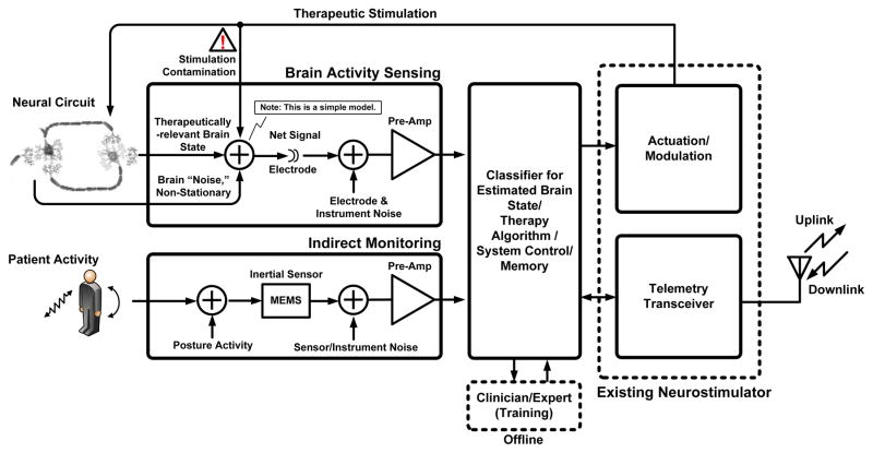
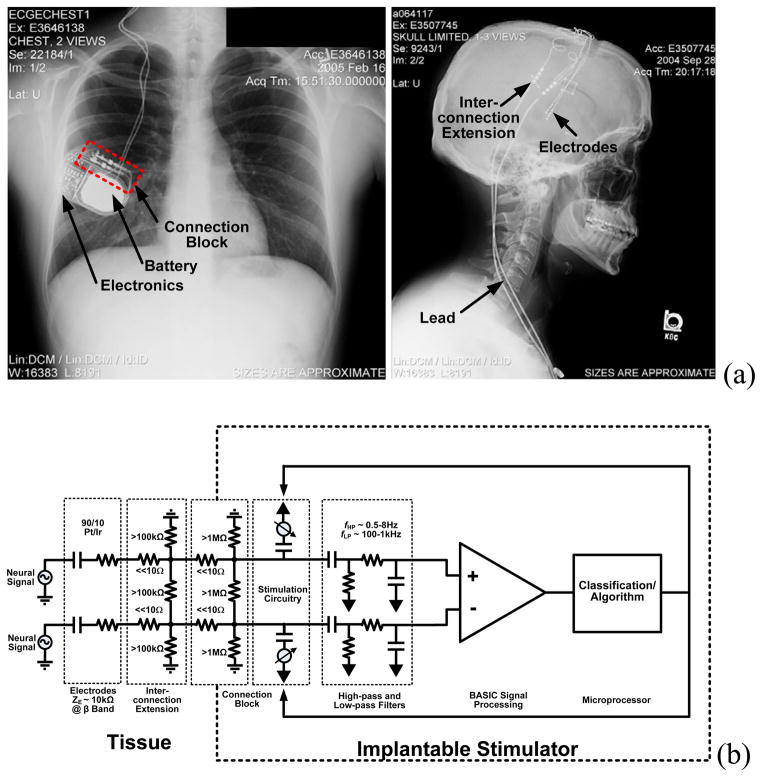
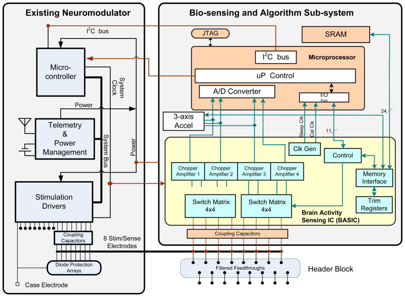
To address the challenges associated with deploying neural interface technology, we designed and built an implantable research tool for chronic use, to discriminate disease state across a broad range of neurological diseases. This is accomplished by using the device to record and identify biomarkers relevant to a broad class of therapies. These new functionalities were added to the existing technology and clinical infrastructure of existing DBS systems. As illustrated in the functional block diagram of Fig. 4, the NIT core is the existing stimulator and telemetry system found in released neurostimulators (ActivaPC™). This design model allows us to take advantage of an implant base of approximately 75,000 devices. A typical DBS implant system is depicted in-vivo with the X-ray in Fig. 5a. The stimulator system provides the core therapy system approved by regulatory bodies and accepted by patients, clinicians, and reimbursement agencies. Furthermore, the architecture is designed to operate in three modes.
Fig. 4.
Functional block diagram for bi-directional neural interface system.
Fig. 5.
(a) General device architecture for a bi-directional neural interface system using existing technology. (b) Equivalent electrical circuit.
In diagnostic mode, signals are recorded, classified and telemetered from the device, without changing therapy. Clinician-researchers can use this mode to collect data and test hypotheses about the relationships between measured signals and disease state.
As biomarker and algorithm research matures, the device has the built-in capability to make therapy adjustments in closed-loop mode for real-time therapy.
Finally, in the standby mode, the sensing capabilities become inert so that the device reverts back to the functionality and power usage of existing devices.
The prototype builds on this architecture with the addition of three major hardware subsystems:
a biopotential (ECoG/LFP) sensing module that amplifies and processes field potentials from the electrodes,
a three axis accelerometer for measuring activity and posture, and
an algorithmic micro-processor for signal classification, telemetry streaming, and system control.
A supplemental recording memory is also included within the algorithmic processor block for logging event-based waveforms for later upload from the implant. The hardware system is controlled with embedded firmware that can be downloaded via telemetry, which facilitates research into classification algorithms.
Referencing Fig. 6, the sensor hardware, algorithm processor, and firmware partition are inserted into the existing infrastructure with well-defined signal pathways in the physical and algorithmic domains. The interface to the neural circuitry is made via a 90–10 Pt-Ir electrode array consisting of four cylindrical electrodes per hemisphere, spaced roughly 1.5 mm apart down a cylindrical lead. The electrode dimensions of these circuits is determined by the anatomy of the neural circuit of interest, and can be adjusted based on the application [15][16]. A model for the electrical pathway is shown in Fig. 5b. Bioelectrical sensing is achieved by measuring bipolar vectors across electrodes contained within one hemisphere using the existing electrode systems for stimulation therapy. Use of low impedance DBS or ECoG electrodes minimizes leakage currents between connection points that may degrade the signal. Typical impedance values are included in Fig. 5b. Stimulation therapy is delivered between electrodes (bipolar) or from electrodes to device case (unipolar). Both the stimulation and sensing electronics are isolated from the tissue through coupling capacitors that eliminate leakage pathways from the device through the electrodes. Connections from the BASIC electronics to the electrode-connector are made through a set of switch matrices and isolation-protection circuitry. In parallel, a custom three-axis accelerometer provides continuous sensing of posture, tremor, and activity. The signals from both the BASIC and the accelerometer can be time-interleaved and passed within the new partition to an ultra-low-power microprocessor. This processor controls the biomarker extraction and event-logging, telemetry uplink, and in restricted modes the therapy delivery. The system uses an 8 Mb SRAM for long-term recording of detected events and storing raw waveforms.
Fig. 6.
Electrical device architecture and system partition for the prototype.
Interfaces to external programming and analysis instruments utilize the existing wireless inductive telemetry link. The sensor configuration and the algorithm firmware can be reconfigured through telemetry for system flexibility and extensibility, and the data stored in SRAM and real-time data can be uplinked for analysis.
Additional infrastructure is placed inside the IPG as well. For example, the telemetry coil to pass information between the implant and external instrument is also embedded within the IPG’s titanium enclosure. Referencing both Figures 5 and 6, the majority of existing DBS infrastructure is used to prototype a viable BMI system. The major change is to the existing IPG through addition of a new sensing and algorithmic sub-system.
2) Custom-Integrated Circuit for Brain Sensing (BASIC)
The BASIC integrated circuit is designed for efficient processing of LFP/ECoG signals. This allows the sensing BMI to meet the combined requirements of microvolt-level signal extraction while drawing minimal power. This is accomplished by taking advantage of the properties of the neural coding in LFP/ECoG signals. The spectral power fluctuations in LFPs, which are the essential biomarkers, have a bandwidth that is one to two orders of magnitude slower than the frequency of the oscillation itself. This suggests a sensing architecture that directly extracts energy in key frequency bands and tracks the relatively slow power fluctuations prior to digitization and algorithmic analysis, similar to the spectral processing paradigm of AM demodulation to extract the audio signal from a high-frequency carrier signal prior to complex processing [30][32][33]. Adopting this strategy reduces overall system power consumption, especially in the digital signal processing and algorithm blocks. As described in [30], the BASIC implements a short-time Fourier transform (STFT) estimation by using a modified chopper-amplification scheme to extract power over a given frequency band. The power band of interest is programmable and can be tuned by programming I/O registers on the BASIC for different applications. Table I outlines the settings. The output power signal has a bandwidth of less than 5 Hz, which greatly reduces the processing rate requirements of downstream digital signal processing and algorithms to keep the power constrained (the algorithm partitioning will be discussed in greater detail in Section II-A-4). For generalized recording in the time-domain, the BASIC acts as a regular linear amplifier [30][34]. The direct extraction of spectral power does impose a noise floor penalty of roughly 2.5x for the same power in the preamplifier due to harmonic sampling properties in the computation of the Fourier transform [30]. For our architecture, however, the total power savings by computing the STFT on-chip, and not in the microprocessor, more than offsets the power penalty of on-chip computation from a total system perspective. This STFT processing approach can be generalized, and has been reported for ECG signal processing and arrhythmia detection [35].
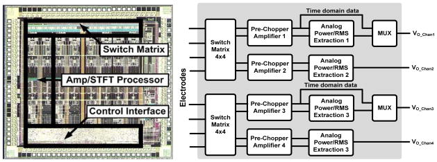
The BASIC can be configured in a flexible manner depending on the needs of the specific algorithm or application protocol. Referring to the die photo in Fig. 7, the BASIC has four independent signal processing channels, with a budget of 5 μW/channel to achieve sub-microvolt resolution; in the time domain, <1 μVRMS resolution in STFT processing mode. These channels can be independently configured to optimize the algorithm or protocol, including using a mixture of time-domain and spectral processing. The trade-off of this configuration is power consumption and memory, particularly for the telemetering and storage of multiple time-domain signals. While the telemetering of RMS or spectral power at a few Hz draws roughly 10 μW, real-time uplinking of time domain data can draw more than 100 times this amount due to telemetry overhead, dominating the system power. This is a common tradeoff with implantable designs, and the clinician researcher must determine the optimal trade-off between signal fidelity, maximal information, storage time, and power consumption for their application. Another degree of freedom that the BASIC provides for the clinician researcher is the switch montage, which allows for sampling of different electrode dipoles in the neural circuit within each array. This allows for sampling multiple dipoles to help guide programming of devices or to focus on the most informative pair for chronic sensing [1][3]. For example, we can simultaneously measure beta and gamma band signals from any pair of electrodes for the life of the implant while sacrificing less than 10% of battery life.
Fig. 7.
Brain activity sensing interface IC (BASIC) die photo with simplified block diagram.
3) Custom-Integrated Inertial Sensor for Activity, Posture, and Tremor Monitoring
The accelerometer is designed to make posture and activity measurements. As described in [39] and illustrated in Fig. 8, the accelerometer consists of a MEMS polysilicon sensor that transduces acceleration to a differential capacitance measurement on the order of 1 fF/g. The sensor can survive shocks in excess of 10 kG, which is possible in a 1 m drop of an IPG. A custom micropower application-specific integrated circuit (ASIC) is designed to convert the capacitance change to a voltage signal that is digitized by the algorithm processor. The sensor can measure +/−5 g, and through extended life testing has demonstrated stabilities of +/−5 mg (one sigma) and a noise floor of while drawing < 1 μW/axis. This is suitable for both the chronic measurement of posture and potentially for activities of daily living. A detailed circuit design overview can be found in [39], and the specifications are summarized in Table 1.
Fig. 8.
MEMS acceleration sensor with capacitance-to-voltage interface (C/V) integrated circuit. The final sensor is encapsulated for manufacturing.
4) Algorithm Architecture Strategy and Canonical Design
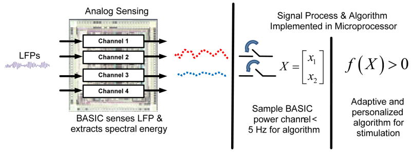
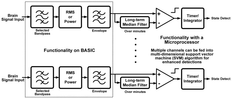
The algorithmic architectural partitioning was designed to balance these constraints and meet the needs of several potential applications. This partitioning leverages the capability of the overall system architecture and the neural coding of many biomarkers. As shown in Fig. 9, the algorithm is split between the spectral estimation circuit on the BASIC IC and digital signal processing firmware running on the microcontroller. The fixed hardware functionality of time domain and spectral processing are efficiently embodied on the BASIC. The more flexible and complex algorithms, such as median filtering and support vector machines, are embodied in firmware where they can be re-configured in downloadable updates through telemetry. The boundary for digitization was chosen at a point where the dynamic range and bandwidth requirements are largely minimized. This helps to keep power to a minimum while balancing flexibility in the digital processing in a manner similar to neuromorphic processors introduced for other biomedical applications [18].
Fig. 9.
Partitioning for signal processing and algorithms.
The algorithm architecture was applied to a canonical design that is applicable to a variety of neurologically-based applications. As illustrated in Fig. 10, the general principle is to track fluctuations in spectral power or RMS within discrete bands against a long-term average and/or other bands’ characteristics. This spectral tracking mode has already found application for motor prosthesis [7], epilepsy detection [40][32], and Parkinson’s on/off state estimation [29]. The algorithm can also be scaled to observe multiple channels for additional specificity, including data from other sensors like the accelerometer, and is amenable to machine learning techniques within the power constraints [32]. A detailed algorithm design for a seizure burden monitor using this algorithm scheme with support vector machines and the BASIC can be found in [32]. From this design example we can estimate that a typical linear support vector machine processing four channels of spectral data from the BASIC draws 20 μW (5 μW/channel) of power for digital computation. Including additional sensor information such as the accelerometer creates a linear increase in power usage as the data rate increases. At this power consumption, updates on a subject’s neurological state can be estimated at the rate of 1 Hz, which is suitable for many applications. Increasing the rate of estimation for applications like BMI is achieved at the proportional power increase.
Fig. 10.
General detection scheme.
III. Physical Implementation and Characterization of the Prototype Implantable System
A. Physical Prototype
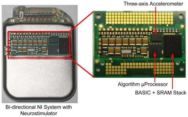
The complete implantable system prototyped using state-of-the-art medical device technology previously approved for chronic human use is shown with a cutaway window in Fig. 11. The BASIC and accelerometer interface were fabricated using a 0.8 μm CMOS process. The BASIC was stacked on the 8 Mb SRAM to provide a module with small form-factor, and the accelerometer interface was packaged with the MEMS die to allow for reflow in a standard manufacturing process. The electrode-interconnect, BASIC, accelerometer, and algorithm processor are in close proximity on the electronic hybrid and shielded to maintain signal integrity by preventing coupling to the stimulation circuits. The right side of Fig. 11 is a close-up of the side of the hybrid board containing the sensing and algorithm electronics. The other side of the hybrid (not pictured) contains the existing stimulator and telemetry electronics. This device has complete bi-directional functionality and is suitable for chronic preclinical research.
Fig. 11.
Physical prototype of the implantable bi-directional BMI system.
B. General System Characterization and Verification
The prototype system, including implantable circuits, electrodes, and telemetry, was tested both on the bench and in a saline tank with recorded subject data. The core therapeutic functionality of the existing stimulator was maintained by the architecture, demonstrated through design verification testing using the production test suite from the predicate device, the ActivaPC™. We also verified that the hardware and firmware in the sensing partition did not impact the stimulation circuitry in the core neurostimulator. In particular, cross-channel isolation was verified to meet existing therapy requirements. This ensured that the additional shunt impedance added to the electrode array would not impact stimulation current flow and deviate therapy settings and efficacy from established norms.
The new components were also verified to operate as expected. The BASIC was verified to consume 2.5 μA/channel from a 2V supply, achieving a signal resolution of 1 μVRMS for a 5 Hz spectral estimation for four channels of operation. The accelerometer was confirmed to draw 1.0 μA and resolve measurements of posture and activity with a minimum resolution of approximately 10 mg (20 Hz bandwidth) and a dynamic range of +/−5 g. The linear support vector machine (SVM) classification algorithm drew an additional 10 μW to classify signals in real-time with one second estimation updates that can adaptively drive the stimulation circuitry and/or log detection events in the memory record.
In addition to demonstrating operational functionality, the system was also verified to pass the design assurance reliability testing expected from an implantable system. These tests included the ability to withstand electrosurgery with a maximum power up to 300 W applied to the LFP/ECoG inputs, defibrillation test with maximum energy up to 360 joules across the electrodes to IPG case, and ESD CDM-model to 500 V. The system has been also verified to maintain a normal performance after X-ray exposure with a total dose of approximately 500 rads. The prototype underwent significant verification to ensure safety for leakage currents and meets all requirements for a class CF instrument per IEC-60601 protocols. Additional testing included CENELEC EMI testing. The performance is summarized in Table 1.
IV. Validation of Sensing Functionality
A. Validation of Posture and Activity-Based Signal Processing
The inertial sensing and algorithmic subsystem was tested for nominal baseline resolution, noise floor, and accuracy, per the specifications of Table 1. The accelerometer hardware and algorithm architecture are similar to that implemented on the RestoreSensor™, a posture responsive spinal cord stimulation system for the treatment of chronic pain. RestoreSensor™ is CE-marked and undergoing U.S. clinical trials at the time of writing. Given the maturity of the inertial measurement subsystem in predicate device architectures, we focused on validation of the novel brain-interface electronics.
B. Applying Motor-Intention Servo Control for Validating Bioelectrical Signal Processing
The relationships between neural information and disease state is poorly understood, making technology validation a significant challenge. To overcome this, we chose to validate a behavioral response in a trained non-human primate performing a one-dimensional motor control task. In contrast to disease state models, this validation paradigm makes it possible to quantify system performance since the neurological state is relatively well known. In addition, this paradigm mimics several key features of the disease state. Both signals have two states with signal level of approximately 1 μVRMS for biomarker discrimination, require spectral analysis to determine the neurological state, and can utilize canonical detection algorithms (see section II-A-4).
A series of tests were performed to highlight the capabilities and trade-offs of the BMI system using an in-vivo model. Particular emphasis was placed on evaluating the trade-offs of different levels of IPG-based signal processing and telemetry rates versus device performance and power usage. Referring to the equivalent electrical model of the device shown in Fig. 5b, the in-vivo protocol was also designed to address the most challenging interfaces in the model as they relate to sensing brain activity. These include the chronic interface between the electrode and the brain, the processing of signals on the IPG hardware and firmware, and the ability to run a feedback control algorithm in real-time.
1) Protocol Overview
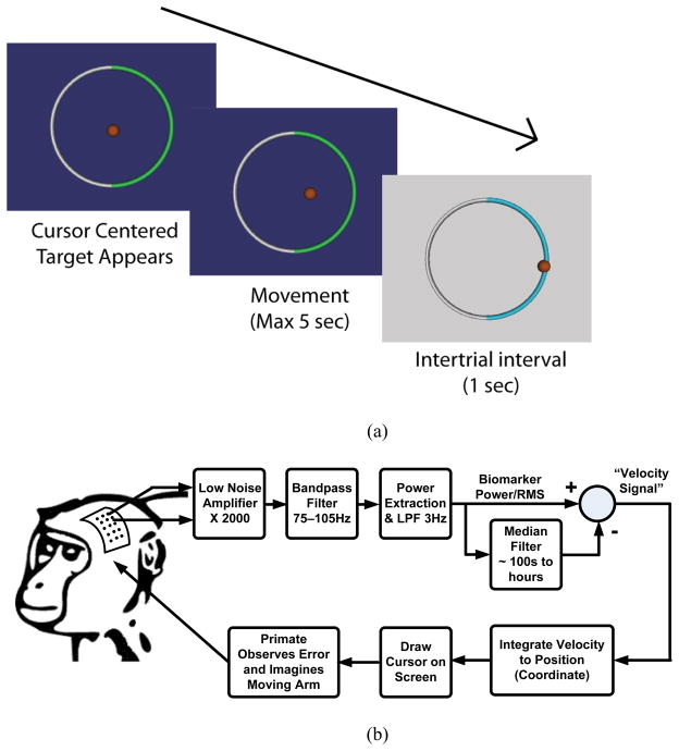
A micro-electrocorticography (μECoG) grid was implanted in a non-human primate (macaca fascicularis) over one hemisphere of primary motor cortex (Area M1). The electrode impedances of the ECoG array were nominally 200 kΩ at the center of the measurement band. This represents a 20x increase in impedance over a typical DBS electrode [34], providing good margin for testing interactions and coupling between the electrodes and the IPG sensing interface. Referencing Fig. 12a, the non-human primate was trained to perform a one-dimensional, two-target selection task using cortical activation, normally associated with motor commands, to control a cursor on a computer screen. At the beginning of each trial a cursor would appear at the center of the video monitor. Next, one of two targets would change colors to indicate the desired target for the trial. Following a 500 ms delay, the cursor would be controlled by the recorded μECoG brain signals. The subject had five seconds to move the cursor to one of the two targets. If neither target was selected within five seconds, the trial ended and was repeated in a pseudo-random order. If the subject selected the correct target, he was given a liquid reward. Fig. 13a illustrates the basic timing of the task.
Fig. 12.
One dimensional motor neuroprosthetic control test. (a) Temporal illustration of target selection task. The cursor is centered, desired target appears, subject moves the cursor using its brain signal, and rests during an inter-trial interval (with possible reward), (b) signal path illustration.
Fig. 13.
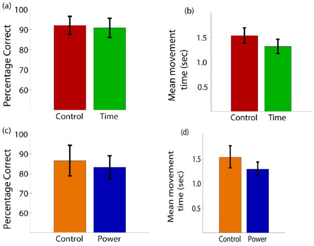
a) The percentage of correct trials for the two conditions of laboratory control (75–105 Hz) and time-domain sampling. Percentages are the total correct targets out of the number of trials where one of the two targets was selected. b) Mean movement time to select one of the targets for the same two conditions. c) Percentage correct for control (80–96 Hz) and on-board power estimation. d) Mean movement time for the two conditions.
The same task was performed by the subject using three different recording setups:
Control mode
Time domain mode
Power mode
The intent was to compare our implantable instrumentation against typical laboratory instrumentation as well as different signal processing modalities, to understand the trade-off between power dissipation and performance. The control setup (control mode) was a wired, externally-powered laboratory recording system (Tucker-Davis Technologies, Alachua, FL) that the non-human primate had been trained to use and had been using to perform brain-control tasks for approximately three months. Signal processing was performed using the digital signal processors of the recording system base station.
The IPG prototype device was tested in two conditions against the control. In time-domain mode the signal was sampled at 200 Hz and transmitted to a receiving computer where the spectral estimation was performed in software (LabView, National Instruments, Austin, TX) to generate a control signal. In the second mode, a spectral power detection mode (power mode) was used, where the spectral energy was estimated directly on the BASIC electronics and transmitted to the receiving computer. In all three cases, the resulting amplitude estimate was normalized in the same way and used to control cursor velocity as the non-human primate performed the two-target selection task.
The control mode was first performed. As illustrated in Fig. 12b, the amplitude of the μECoG signals between 75–105 Hz was used for control. An envelope detection method of bandpass filtering, rectifying, and low-pass filtering was used for the signal. The band-pass filtering was done using a standard 16th order Butterworth filter to limit the signal to the 75–105 Hz frequency band. The resulting signal was then full-wave rectified by taking the absolute value of the signal. Finally, the signal was low-pass filtered at 3 Hz to smooth the spectral envelope and estimate the amplitude. The amplitude estimate was then normalized by subtracting the running mean for the previous 100 seconds and dividing by the root-mean-square of this signal for the past 100 seconds. This signal was then mapped to the velocity of the cursor. In the experiments described here, electrodes for the two channels were spaced 15 mm apart to provide cursor control in a push-pull decoding scheme. A large amplitude signal between 75–105 Hz moves the cursor to the left while a small amplitude control signal relative to the running average causes the cursor to move to the right. An amplitude increase on one electrode caused the cursor to move to the left while an increase on the other moved the cursor to the right. The use of a push-pull scheme serves as a first-order control against actuation from far-field sources such as muscle EMG or EMI coupling. For this particular subject, the cortical activity was modulated much more under one electrode while the other electrode remained relatively constant. Thus, all recorded signal amplitudes reported here are for the electrode showing the modulated activity. Time-domain mode was then performed using the prototype device with similar settings.
For the power estimation mode, the amplitude of the signal was limited to the frequency band of 80–96 Hz. As a control comparison, the decoding for the wired laboratory recording system for one block of trials was altered to use the same sized band-pass filter between 80–96 Hz for amplitude estimation. Using the 80–96 Hz band was a novel change for the non-human primate over the two days of testing with the BASIC device (the animal had used 75–105 Hz band for months prior to this study).
2) Validation Results
The closed-loop control experiments were performed over a period of two days. For the time domain and corresponding control setup, the subject completed 64 correct trials each day with 32 correct movements to the right and 32 correct movements to the left. Thus, the analysis includes a total of 128 correct trials as well as all incorrect trials across two days. The target for each trial was pseudo-randomly chosen in blocks of eight such that the non-human primate was required to complete four right targets and four left targets before moving to the next block. Performance was measured as a percentage of the number of correct targets selected to the total number of targets presented. Trials where neither the left or right target were selected within 5 seconds were not included in the percentage or mean movement time (<8 percent of trials in all conditions). Fig. 13a shows the percentage correct for the control (75–105 Hz) and time mode. The subject hit over 90 percent of the targets correctly in both cases and there was no statistical difference (using 95 percent confidence intervals) in performance between the control setup and the prototype device when transmitting data in the time domain. In addition, the mean movement time required to select a correct target was calculated and is shown in Fig. 13b. The mean movement time to select a target was between 1.31 seconds for the prototype device, while it was 1.53 seconds for the control condition.. Regardless, when transmitting signals in the time domain, the prototype device performance in terms of percentage correct and speed was essentially equivalent to the control system designed for recording neural signals in the laboratory setting.
The performance metrics (percentage correct and mean movement time) were also compared between device-estimated power and the control condition between 80–96 Hz. Fig. 13c shows that the percentage correct dropped to 86 percent for the control condition when only 80–96 Hz was used for control. Likewise, control with power estimation on the BASIC device resulted in 83 percent correct target hit rate. Once again, the mean movement times (Fig. 13d) were comparable with the prototype being slightly faster than the control condition and similar to what was observed during the time domain setup. These results suggest that the performance of the device’s power estimation was very similar to the control system when the equivalent control frequency band of 80–96 Hz was used.
3) Analysis of Results using Detection Theory
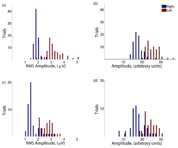
A more rigorous validation method involves the use of binary classification information theory. To better evaluate the discriminability of the recorded signals during the different conditions, the signals were examined in a signal detection framework. Fig. 14 shows the histograms of the signal amplitude within the control frequency band for each trial for the different recording setups. The control condition (Fig. 14) shows the signal amplitudes between 75–105 Hz in the control channel for both the left and right targets. For this channel, the non-human primate needed to increase the amplitude to move the cursor to the left or decrease it to move to the right to successfully complete the trial. All trials (correct, incorrect, and timed out) are included in the plot. There is a clear separation between the trials depending on which target was presented, as one expects for a subject achieving a high percentage correct. During trials where the right target appeared, the mean amplitude of the signal on the recording electrode was 1.83 μVRMS. For left trials, the mean amplitude increased to 3.13 μVRMS. Thus, in a simple two target task, successful state classification depends on a given device’s ability to detect this difference of 1.30 μVRMS. The separation between the two conditions can further be quantified by the sensitivity index (d′):
Fig. 14.
Histograms of the signal amplitudes for trials where the desired target was left (red) and right (blue). The four conditions are a) control (75–105 Hz), b) time-domain mode, c) control (80–96 Hz), and d) power mode.
Here, μ represents the mean RMS signals and σ is the standard deviation of the signal. The d′ statistic provides a mean difference between the two target conditions in units of standard deviations. The d′ for the control condition was 2.88. Fig. 14b shows the histogram for when the time domain signal from the prototype device was used to estimate the amplitude of the signal between 75–105 Hz. Once again, there is a clear separation between the two target conditions. The corresponding d′ was 2.73 standard deviations of separation between the two means. This modest decrease in separation is likely caused by the high electrode impedance, which attenuates the signal prior to entering the BASIC.
In Fig. 14c and 14d, the amplitude of the signal between 80–96 Hz is shown. There is clearly less separation and more overlap between the two target conditions when only the 80–96 Hz control band was used. During the control condition (Fig. 14c), the mean amplitude between 80–96 Hz was 2.58 μVRMS and 1.59 μVRMS for the left and right targets, respectively. This difference of 0.99 μVRMS resulted in a d′ of 2.00 standard deviations. Finally, Fig. 14d shows the amplitude difference between targets when the on-board BASIC electronics were used for power estimation. The left versus right separation had a d′ of 1.41 standard deviations, suggesting that the noise contribution of the spectral processing IC is now on par with the background variance of the brain state.
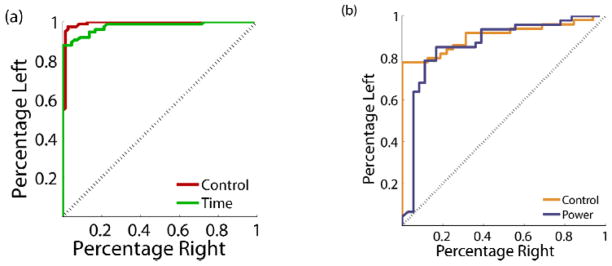
Signal detection for the three conditions can be visualized using the receiver operating characteristic (ROC) curve, a standard method of evaluating binary classifiers. The ROC curve plots the percent of left targets correctly classified versus the percentage of right targets that would be incorrectly classified for various threshold levels. A plot along the diagonal indicates only chance performance while a curve along the far upper-left indicates perfect discriminability. Fig. 15a shows the ROC curves for the control condition (75–105 Hz) compared to the time-domain condition and illustrates their similar level of performance. This can be quantified by the area under the curve (AUC) and represents the probability that the amplitude of a randomly selected left trial will be greater than a randomly selected right trial. The control and time domain conditions had AUC values of 0.98 and 0.96, respectively. Once again, the control and time-domain conditions using the full 75–105 Hz band were significantly better than the power estimation and control conditions using 80–96 Hz (Fig. 15b) which were in turn significantly better than chance. An AUC of 0.87 was calculated for the control condition between 80–96 Hz while 0.84 was the AUC in the power estimate condition.
Fig. 15.
Receiver operating characteristic (ROC) curve for the different conditions. For a series of thresholds, the curve traces out the percentage of left target trials above the threshold versus the number of right target trials above the same threshold. a) Control and time-domain. b) Control and power estimation.
From this data, we conclude that the nominal ROC curves in both modes of operation are essentially equivalent between off-the-shelf research equipment and our custom integrated circuitry, with the time-domain data streaming providing the highest fidelity signal as expected. The performance degradation observed while running in the prototype’s power mode was predominately caused by the shift in control bandwidth; the prototype essentially matched the control performance when the bandwidths of the two systems were adjusted to the same value. The d′ metric does demonstrate that for this bandwidth of spectral power, approximately 1 μVRMS resolution is our approximate floor for accurate signal processing and detection. The performance of the system for all use cases is summarized in Table 2. All range estimates represent the 95 percent confidence intervals. The power-sensitivity/specificity trade-offs will be summarized in the Discussion section.
Table 2.
Performance summary of system validation with a one dimensional motor neuroprosthetic control (95 percent confidence intervals in parenthesis)
| Number Correct | Number Incorrect | Percentage (%) | Mean Movement Time (sec) | d′ | Area under ROC curve | |
|---|---|---|---|---|---|---|
| Control (75–105 Hz) | 128 | 11 | 92.1 (+/− 4.5) | 1.53 (0.96–2.45) | 2.88 | 0.98 |
| Time | 128 | 13 | 90.8 (+/−4.8) | 1.31 (0.83–2.09) | 2.73 | 0.96 |
| Control (80–96 Hz) | 64 | 10 | 86.5 (+/− 7.8) | 1.53 (0.81–2.90) | 2.00 | 0.87 |
| Power | 128 | 26 | 83.1 (+/− 5.9) | 1.29 (0.83–2.00) | 1.41 | 0.84 |
C. Characterization of Sense-Stimulation Interactions and Constraints
Ultimately, the goal of the bi-directional neural interface is to allow information to pass to and from the device with minimal interactions or constraints. A significant challenge in combining sensing and stimulation in a bi-directional system is dealing with signal cross-contamination as illustrated in Fig. 4. The signals we want to sense are on the order of microvolts, while the signals we are injecting (the stimulation) are on the order of volts. The implementation of a practical bi-directional system is important for many therapies where we do not want to impose overly restrictive constraints such as simply disallowing coincident sensing and stimulation, which would limit both detection diagnostics and potential closed-loop strategies.
To overcome this challenge, several methods are employed in the prototype system. Reducing the differential signal relies upon careful placement of the electrodes and sense-stimulation configuration. The strategy is to reduce the differential signal seen by the preamplifier and to filter it out by separating the stimulation frequency from the sensing frequency of interest. Sensing electrode dipoles can be configured to be orthogonal with respect to the stimulation electrode dipole [32]. The residual stimulation signal seen across the sensing dipole, therefore, becomes common-mode signal for the sensing channel. With orthogonal dipoles, the net stimulation artifact seen by the sensing dipole and amplifier is zero. The amplifier must only reject the common-mode stimulation artifact, and our chances for extracting a signal are greatly increased given the high-common-mode rejection ratio of the preamplifier. The other key method employed in all electrode configurations is to take advantage of the spectral filtering properties of the BASIC. In particular, the architecture of the BASIC is capable of rejecting signals that are out of its tuned band. Saturation is avoided by filtering the signal before significant gain is applied as part of the STFT processing, and the BASIC includes an additional 100 Hz input low-pass filter versus the design in [30]. This allows for the possibility of delivering stimulation therapy in one spectral band and sensing in another at the same time, off of the same lead, but not the same electrode.
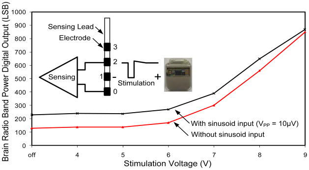
The ability of the system to perform sensing during the delivery of stimulation was tested in a saline tank. Fig. 16 shows the results from a test where 145 Hz stimulation was delivered between electrode 1 and the IPG. A 24 Hz signal, representing typical β band biomarkers like those found in epilepsy and Parkinson’s disease, with 10 μVPP (3 μVRMS) amplitude was injected into the tank and sensed across electrodes 0 and 2 using the BASIC. It was compared to results obtained using the same stimulation but no test signal. The separation of the two curves indicates a promising ability to sense during delivery of stimulation, especially since most clinical therapy is delivered using 5V of amplitude or less. The limitations of the current test include the relative symmetry of the saline tank, which provides almost optimal common-mode rejection ratio (CMRR) performance. In an actual in-vivo setting, discrepancies in tissue impedance will likely make the system more susceptible to cross-contamination. This motivates the next generation of testing in chronic implantable models of disease states.
Fig. 16.
Sensing capability in the presence of 145Hz stimulation.
V. Discussion
The prototype architecture validated in this protocol addresses several of the major challenges to the development of an implantable bi-directional BMI device. In our view, the adoption of BMI methods is limited by a combination of practical, technical issues and the alignment of available technology to address significant unmet clinical needs. This includes striking an acceptable balance between invasiveness and risks with patient benefits and outcomes [7].
The architecture was designed to address both of these issues. To address the technical challenges we designed and manufactured custom-integrated sensing and processing capability in two paradigms relevant for a broad range of applications. Based on early acute data, both the custom integrated inertial sensing and spectral processing circuits have the required resolution to detect clinically-relevant physiological activity at power levels suitable for chronic implantable applications [31]. While the inertial hardware and algorithm has already undergone CE-marking, the brain state detection circuitry is still novel. To provide greater confidence in its capabilities, the signal chain was validated by the acute motor prosthesis. Using this validation paradigm, we demonstrated similar ROC curve performance compared to off-the-shelf research hardware in a protocol reflecting the lower signal levels reported in therapy applications [31]. The differences in the d′ metric does indicate that we are approaching the ultimate resolution capability of the device at approximately 1 μVRMS, the lower limit of expected signals from DBS applications, but we can still maintain meaningful algorithm performance. In addition, the system input impedance is designed to be approximately 1 MΩ at the center of the measurement band, which is sufficient for DBS-like electrodes with normal impedance of 10 kΩ However, with the 200 kΩ micro-electrocorticography (μECoG) grid impedance from this protocol, a 20 percent signal attenuation penalty is expected and external interference is exacerbated. Therefore, this preclinical validation activity truly represented a worst case situation.
The choice of sensing methodology also represents a pragmatic approach to BMI implementation. The restriction of technology to materials and components proven within existing implant devices greatly increases the viability of translation. The use of field potentials, which is predominantly motivated by the applications in neurological disease treated by existing stimulation therapies, also provides some degree of confidence in more stable measurements. Recent work has established the viability of recording from basal ganglia targets beyond the operating room, and suggests that impedance and field potential stabilize in the weeks following surgery [3][28]. Similarly, the preclinical validation work performed as part of this work used epidural electrodes in place for several months, which have demonstrated stable recordings. Others have shown signal stability in subdural implants for over a year [41]. With the technical issues appearing to be resolved, we can now focus on translational challenges.
In parallel with technical issues, significant challenges remain prior to deployment of BMI methodologies to a clinical setting. To attempt to address these issues we designed the system to address existing unmet needs in established therapies that already have clinical acceptance, reimbursement structures, and a patient care continuum, such as Parkinson’s disease, epilepsy (CE-marked) and future indications under investigation such as depression or stroke. In addition to motivating our technical choice of using spectral processing of field potentials as sensing methodology, this broader application requires flexibility in the system partitioning for adjusting the algorithms and sensor characteristics as needed. Through telemetry, the device can be tailored for specific applications in-vivo. In principle, this allows the same core device to be used to guide programming in Parkinson’s disease based on detected signals from the electrodes, to keep a seizure burden log and/or dynamically respond to seizures in epilepsy, or to operate as a bi-directional interface for a motor prosthesis. This flexibility is provided by firmware updates, which also allow the same device to evolve from a data collection tool to a diagnostic/monitoring instrument to a closed-loop system for various applications. These updates will ultimately be gated by regulatory approval as the performance at each stage is verified and validated, but the infrastructure for discovery is now in place. The system was also designed and verified for performance within the usual care continuum of implantable devices. This includes the ability to withstand the body’s harsh environment, ESD, electrosurgery, defibrillation, and other medical device assurance testing. The device also uses implantation methods demonstrated with over 75,000 procedures to date, increasing the expected reliability of the system. We believe that the unique combination of performance, flexibility, and reliability make this architecture a practical milestone on the roadmap toward translation of BMI concepts into a chronic clinical setting.
Building on the architecture of an existing device and clinical infrastructure does put constraints on the design and perhaps its achievable system performance. This is particularly the case for the bioelectrical sensing capability of the device. The limited channels and the restriction to local field potential/ECoG sensing do limit the ultimate information throughput compared to spike-based systems with large numbers of channels [14][17]. Along similar lines, recent work in seizure detection suggests that there will be potential motivation to scale field potential measurements down further, as microseizures at higher spatiotemporal frequencies might be a better seizure predictor than large scale ECoG [44]. We feel that this design choice balances the limitations of current BMI technology and the required degrees of freedom for detection of neurological states in our initial applications. For the first generation of systems, our fidelity of field potentials at the square millimeter level does address several unmet needs for programming guidance and an accurate two-state monitor with a bias for reliability. Ultimately the clinical solution might be biased to simple but robust methods such as those found in cardiac closed-loop systems. Supporting this view, recent research has suggested an approximate equivalency of LFPs and single-unit activity in prosthesis applications [42][7][43].
The results of the one-dimensional BMI protocol highlight a fundamental trade-off in the design partition of a BMI system. The key issue is how to balance the embedded processing and its power efficiency against potential performance limitations; essentially, does one run the algorithm inside the device or external to it? The advantage of performing computations external to the device is flexibility and maintenance of maximal information, but this comes at the expense of greater power dissipation in high-rate signal processing and telemetry. Alternatively, one can partition the system to compute algorithms internal to the device with the advantage of better power efficiency, but at the potential cost of limited flexibility that might impact detection accuracy.
We partitioned our system to optimize for spectral processing applications of LFP and ECoG applications to minimize power utilization. This design approach was validated in the protocol. The ROC curves are essentially identical between the device and off-the-shelf instrumentation for both time-domain and low-power spectral processing. The prototype device did show modest performance degradation in the spectral power estimation mode, but the majority of performance degradation is suggested to result from the shift in the bandwidth as opposed to fundamental device capability. The constraints of the signal processing chain impact our performance compared to raw data streaming, as we could not precisely replicate the control paradigm in-silico. This degradation is balanced by more than a 20x improvement in power dissipation, largely enabled by a reduction in telemetry processing, data sampling, and data processing overhead, which translates directly into device longevity. While the sensing device running in time-domain mode with streaming telemetry real-time might run for approximately two years in the prototype, it would last for several decades running in the spectral processing domain. Although the limitations are modest in impact, both within our laboratory and in several other research groups, a new generation of custom integrated circuits is being developed that reduce the impact of embedded processing with more powerful algorithmic capability and a larger number of amplifier channels. This should help to mitigate the current trade-offs of the presented device in the future [45][46].
VI. Conclusion
This paper presented a prototype bi-directional neural interface system. The new device added sensing capabilities and algorithm processing to an approved neurostimulator architecture. The device was verified on the bench to provide chronic measurement capabilities while still being robust to electrostatic discharge, electrosurgery, defibrillation, and other medical device requirements per standard design assurance testing. The demonstrated ability to sense microvolt signals in the presence of therapeutic stimulation levels in a saline tank was demonstrated as a key feature to potentially enable continuous closed-loop control in the future. Although the concurrent bi-directionality of the device was not tested in the non-human primate model, the newly implemented recording and processing elements of the device were preclinically validated using a BMI paradigm, providing quantitative validation of the architecture’s ability to detect brain signals with acceptable sensitivity while operating at microwatt levels. Future experiments will validate concurrent bi-directionality in closed loop BMI experiments for prosthesis and broader disease state applications. The ECoG-based prosthesis test was used as an effective technology validation method for a broad range of neuromodulation therapy applications, including epilepsy and Parkinson’s detection, given the similar signal encoding properties and signal levels. By leveraging existing technology and clinical practice, and expanding the scope of applications to include accepted implant devices today, the device prototype represents a key initial milestone towards practical BMI and its translation to chronic clinical research.
Acknowledgments
The authors wish to acknowledge Dave Carlson, Dave Linde, Kelly Wei, Rahul Gupta from Medtronic Neuromodulation, Jordan Williams from Washington University, and Dr. Peter Brown for technical support related to this paper. Parts of this work were supported by NIH R01EB009103.
Footnotes
Disclosures
Dan Moran owns stock in the company, Neurolutions.
References
- 1.Kuhn AA, et al. High-frequency stimulation of the subthalamic nucleus suppresses oscillatory Beta activity in patients with Parkinson’s disease in parallel with improvement in motor performance. Journal of Neuroscience. 2008;28(24):6165. doi: 10.1523/JNEUROSCI.0282-08.2008. [DOI] [PMC free article] [PubMed] [Google Scholar]
- 2.Rossi L, et al. Subthalamic local field potential oscillations during ongoing deep brain stimulation in Parkinson’s disease. Brain research bulletin. 2008;76(5):512–521. doi: 10.1016/j.brainresbull.2008.01.023. [DOI] [PubMed] [Google Scholar]
- 3.Ince NF, et al. Selection of Optimal Programming Contacts Based on Local Field Potential Recordings From Subthalamic Nucleus in Patients With Parkinson_s Disease. Neurosurgery. 2010;67(2):390–397. doi: 10.1227/01.NEU.0000372091.64824.63. [DOI] [PMC free article] [PubMed] [Google Scholar]
- 4.Litt B, Echauz J. Prediction of epileptic seizures. The Lancet Neurology. 2002;1(1):22–30. doi: 10.1016/s1474-4422(02)00003-0. [DOI] [PubMed] [Google Scholar]
- 5.Mormann F, Elger CE, Lehnertz K. Seizure anticipation: from algorithms to clinical practice. Current Opinion in Neurology. 2006;19(2):187–193. doi: 10.1097/01.wco.0000218237.52593.bc. [DOI] [PubMed] [Google Scholar]
- 6.Mormann F, Andrzejak RG, Elger CE, Lehnertz K. Seizure prediction: the long and winding road. Brain. 2007;130(2):314. doi: 10.1093/brain/awl241. [DOI] [PubMed] [Google Scholar]
- 7.Schwartz AB, Cui XT, Weber DJ, Moran DW. Brain-controlled interfaces: movement restoration with neural prosthetics. Neuron. 2006;52(1):205–220. doi: 10.1016/j.neuron.2006.09.019. [DOI] [PubMed] [Google Scholar]
- 8.Leuthardt EC, Schalk G, Moran D, Ojemann JG. The emerging world of motor neuroprosthetics: a neurosurgical perspective. Neurosurgery. 2006;59(1):1. doi: 10.1227/01.NEU.0000221506.06947.AC. [DOI] [PubMed] [Google Scholar]
- 9.Hatsopoulos NG, Donoghue JP. The science of neural interface systems. Annu Rev Neurosci. 2009;32:249–66. doi: 10.1146/annurev.neuro.051508.135241. [DOI] [PMC free article] [PubMed] [Google Scholar]
- 10.Debener S, Beauducel A, Nessler D, Brocke B, Heilemann H, Kayser J. Is Resting Anterior EEG Alpha Asymmetry a Trait Marker for Depression? Neuropsychobiology. 2000;41(1):31–37. doi: 10.1159/000026630. [DOI] [PubMed] [Google Scholar]
- 11.Hochberg LR, et al. Neuronal ensemble control of prosthetic devices by a human with tetraplegia. Nature. 2006;442(7099):164–171. doi: 10.1038/nature04970. [DOI] [PubMed] [Google Scholar]
- 12.Kennedy PR, Bakay RA. Restoration of neural output from a paralyzed patient by a direct brain connection. Neuroreport. 1998;9(8):1707–11. doi: 10.1097/00001756-199806010-00007. [DOI] [PubMed] [Google Scholar]
- 13.Kempf F, et al. Premovement activities in the subthalamic area of patients with Parkinson’s disease and their dependence on task. European Journal of Neuroscience. 2007;25(10):3137–3145. doi: 10.1111/j.1460-9568.2007.05536.x. [DOI] [PubMed] [Google Scholar]
- 14.Ryu SI, Shenoy KV. Human cortical prostheses: lost in translation? Neurosurg Focus. 2009;27(1):E5. doi: 10.3171/2009.4.FOCUS0987. [DOI] [PMC free article] [PubMed] [Google Scholar]
- 15.Nolte J. The Human Brain: An Introduction to its Functional Anatomy. 6. Mosby; 2008. [Google Scholar]
- 16.Butson CR, McIntyre CC. Role of electrode design on the volume of tissue activated during deep brain stimulation. Journal of Neural Engineering. 2006;3:1. doi: 10.1088/1741-2560/3/1/001. [DOI] [PMC free article] [PubMed] [Google Scholar]
- 17.Harrison RR, et al. A Low-Power Integrated Circuit for a Wireless 100-Electrode Neural Recording System. Solid-State Circuits, IEEE Journal of. 2007;42(1):123–133. [Google Scholar]
- 18.Sarpeshkar R. Brain power - borrowing from biology makes for low power computing [bionic ear] Spectrum, IEEE. 2006;43(5):24–29. [Google Scholar]
- 19.Krusienski D, Schalk G, McFarland D, Wolpaw J. A Mu-Rhythm Matched Filter for Continuous Control of a Brain-Computer Interface. Biomedical Engineering, IEEE Transactions on. 2007;54(2):273–280. doi: 10.1109/TBME.2006.886661. [DOI] [PubMed] [Google Scholar]
- 20.Fabiani G, McFarland D, Wolpaw J, Pfurtscheller G. Conversion of EEG activity into cursor movement by a brain-computer interface. 2004. [DOI] [PubMed] [Google Scholar]
- 21.Beshel J, Kopell N, Kay LM. Olfactory Bulb Gamma Oscillations Are Enhanced with Task Demands. J Neurosci. 2007 Aug;27(31):8358–8365. doi: 10.1523/JNEUROSCI.1199-07.2007. [DOI] [PMC free article] [PubMed] [Google Scholar]
- 22.Kay LM, Stopfer M. Information processing in the olfactory systems of insects and vertebrates. Seminars in Cell & Developmental Biology. 2006 Aug;17(4):433–442. doi: 10.1016/j.semcdb.2006.04.012. [DOI] [PubMed] [Google Scholar]
- 23.Womelsdorf T, Fries P, Mitra PP, Desimone R. Gamma-band synchronization in visual cortex predicts speed of change detection. Nature. 2006 Feb;439(7077):733–736. doi: 10.1038/nature04258. [DOI] [PubMed] [Google Scholar]
- 24.Siegel M, Donner TH, Oostenveld R, Fries P, Engel AK. Neuronal Synchronization along the Dorsal Visual Pathway Reflects the Focus of Spatial Attention. Neuron. 2008 Nov;60(4):709–719. doi: 10.1016/j.neuron.2008.09.010. [DOI] [PubMed] [Google Scholar]
- 25.Firpi H, Smart O, Worrell G, Marsh E, Dlugos D, Litt B. High-Frequency Oscillations Detected in Epileptic Networks Using Swarmed Neural-Network Features. Annals of Biomedical Engineering. 2007;35(9):1573–1584. doi: 10.1007/s10439-007-9333-7. [DOI] [PubMed] [Google Scholar]
- 26.Smart O, Worrell G, Vachtsevanos G, Litt B. Automatic detection of high frequency epileptiform oscillations from intracranial EEG recordings of patients with neocortical epilepsy. Technical, Professional and Student Development Workshop, 2005 IEEE Region 5 and IEEE Denver Section; 2005. pp. 53–58. [Google Scholar]
- 27.Worrell GA, Parish L, Cranstoun SD, Jonas R, Baltuch G, Litt B. High-frequency oscillations and seizure generation in neocortical epilepsy. Brain. 2004 Jul;127(7):1496–1506. doi: 10.1093/brain/awh149. [DOI] [PubMed] [Google Scholar]
- 28.Marceglia S, Rossi L, Foffani G, Bianchi A, Cerutti S, Priori A. Basal ganglia local field potentials: applications in the development of new deep brain stimulation devices for movement disorders. Expert Review of Medical Devices. 2007;4(5):605–614. doi: 10.1586/17434440.4.5.605. [DOI] [PubMed] [Google Scholar]
- 29.Loukas C, Brown P. Online prediction of self-paced hand-movements from subthalamic activity using neural networks in Parkinson’s disease. Journal of Neuroscience Methods. 2004 Aug;137(2):193–205. doi: 10.1016/j.jneumeth.2004.02.017. [DOI] [PubMed] [Google Scholar]
- 30.Avestruz A, et al. A 5 μW/Channel Spectral Analysis IC for Chronic Bidirectional Brain Machine Interfaces. IEEE Journal of Solid-State Circuits. 2008;43(12):3006–3024. [Google Scholar]
- 31.Yoshida F, et al. Value of subthalamic nucleus local field potentials recordings in predicting stimulation parameters for deep brain stimulation in Parkinson’s disease. Journal of Neurology, Neurosurgery & Psychiatry. 2010;81(8):885–889. doi: 10.1136/jnnp.2009.190918. [DOI] [PubMed] [Google Scholar]
- 32.Shoeb A, Carlson D, Panken E, Denison T. A micropower support vector machine based seizure detection architecture for embedded medical devices. Conference Proceedings: … Annual International Conference of the IEEE Engineering in Medicine and Biology Society. IEEE Engineering in Medicine and Biology Society. Conference; 2009; 2009. pp. 4202–4205. [DOI] [PubMed] [Google Scholar]
- 33.Jochum T, Denison T, Wolf P. Integrated circuit amplifiers for multi-electrode intracortical recording. Journal of Neural Engineering. 2009;6(1):012001. doi: 10.1088/1741-2560/6/1/012001. [DOI] [PubMed] [Google Scholar]
- 34.Denison T, Consoer K, Kelly A, Hachenburg A, Santa W. A 2.2 μW 94nV/√Hz, Chopper-Stabilized Instrumentation Amplifier for EEG Detection in Chronic Implants. Solid-State Circuits Conference, 2007. ISSCC 2007. Digest of Technical Papers. IEEE International; 2007. pp. 162–594. [Google Scholar]
- 35.Yazicioglu R, Kim Sunyoung, Torfs T, Merken P, Van Hoof C. A 30μW Analog Signal Processor ASIC for biomedical signal monitoring. Solid-State Circuits Conference Digest of Technical Papers (ISSCC), 2010 IEEE International; 2010. pp. 124–125. [Google Scholar]
- 36.Weinberger M, et al. Beta Oscillatory Activity in the Subthalamic Nucleus and Its Relation to Dopaminergic Response in Parkinson’s Disease. J Neurophysiol. 2006 Dec;96(6):3248–3256. doi: 10.1152/jn.00697.2006. [DOI] [PubMed] [Google Scholar]
- 37.Starkstein SE, Mayberg HS, Leiguarda R, Preziosi TJ, Robinson RG. A prospective longitudinal study of depression, cognitive decline, and physical impairments in patients with Parkinson’s disease. Journal of Neurology, Neurosurgery & Psychiatry. 1992 May;55(5):377 –382. doi: 10.1136/jnnp.55.5.377. [DOI] [PMC free article] [PubMed] [Google Scholar]
- 38.Parikh RM, Robinson RG, Lipsey JR, Starkstein SE, Fedoroff JP, Price TR. The Impact of Poststroke Depression on Recovery in Activities of Daily Living Over a 2-Year Follow-up. Arch Neurol. 1990 Jul;47(7):785–789. doi: 10.1001/archneur.1990.00530070083014. [DOI] [PubMed] [Google Scholar]
- 39.Denison T, Consoer K, Santa W, Hutt M, Mieser K. A 2 μW Three-Axis MEMS-based Accelerometer. Instrumentation and Measurement Technology Conference Proceedings, 2007. IMTC 2007. IEEE; 2007. pp. 1–6. [Google Scholar]
- 40.Osorio I, Frei MG, Wilkinson SB. Real-Time Automated Detection and Quantitative Analysis of Seizures and Short-Term Prediction of Clinical Onset. Epilepsia. 1998;39(6):615–627. doi: 10.1111/j.1528-1157.1998.tb01430.x. [DOI] [PubMed] [Google Scholar]
- 41.Chao ZC, Nagasaka Y, Fujii N. Long-term asynchronous decoding of arm motion using electrocorticographic signals in monkeys. Front Neuroengineering. 2010;3:3. doi: 10.3389/fneng.2010.00003. [DOI] [PMC free article] [PubMed] [Google Scholar]
- 42.Heldman D, Wang W, Chan S, Moran D. Local Field Potential Spectral Tuning in Motor Cortex During Reaching. IEEE Transactions on Neural Systems and Rehabilitation Engineering. 2006;14(2):180–183. doi: 10.1109/TNSRE.2006.875549. [DOI] [PubMed] [Google Scholar]
- 43.Ray S, Crone NE, Niebur E, Franaszczuk PJ, Hsiao SS. Neural correlates of high-gamma oscillations (60–200 Hz) in macaque local field potentials and their potential implications in electrocorticography. J Neurosci. 2008;28(45):11526–36. doi: 10.1523/JNEUROSCI.2848-08.2008. [DOI] [PMC free article] [PubMed] [Google Scholar]
- 44.Stead M, et al. Microseizures and the spatiotemporal scales of human partial epilepsy. Brain. 2010 Sep;133(9):2789–2797. doi: 10.1093/brain/awq190. [DOI] [PMC free article] [PubMed] [Google Scholar]
- 45.Chae Moo Sung, Liu Wentai, Sivaprakasam M. Design Optimization for Integrated Neural Recording Systems. Solid-State Circuits, IEEE Journal of. 2008;43(9):1931–1939. [Google Scholar]
- 46.Rapoport BI, Wattanapanitch W, Penagos HL, Musallam S, Andersen RA, Sarpeshkar R. A biomimetic adaptive algorithm and low-power architecture for implantable neural decoders. Conference Proceedings: … Annual International Conference of the IEEE Engineering in Medicine and Biology Society. IEEE Engineering in Medicine and Biology Society. Conference; 2009. pp. 4214–4217. [DOI] [PMC free article] [PubMed] [Google Scholar]


