Abstract
In an effort to develop an implantable optical perfusion and oxygenation sensor, based on multiwavelength reflectance pulse oximetry, we investigate the effect of source–detector separation and other source-detector characteristics to optimize the sensor’s signal to background ratio using Monte Carlo (MC) based simulations and in vitro phantom studies. Separations in the range 0.45 to 1.25 mm were found to be optimal in the case of a point source. The numerical aperture (NA) of the source had no effect on the collected signal while the widening of the source spatial profile caused a shift in the optimal source-detector separation. Specifically, for a 4.5 mm flat beam and a 2.4 mm × 2.5 mm photodetector, the optimal performance was found to be when the source and detector are adjacent to each other. These modeling results were confirmed by data collected from in vitro experiments on a liver phantom perfused with dye solutions mimicking the absorption properties of hemoglobin for different oxygenation states.
OCIS codes: (170.1470) Blood or tissue constituent monitoring; (170.3660) Light propagation in tissues; (280.1415) Biological sensing and sensors; (300.6340) Spectroscopy, infrared; (290.1990) Diffusion
1. Introduction
According to the Organ Procurement and Transplantation Network (OPTN) and the Scientific Registry of Transplant Recipients (SRTR), in their 2009 OPTN/SRTR report (Table 1.3), between the years 1999 and 2008 the number of registrations on the waitlist for liver transplant in the United States at the end of each year ranged between 14,165 and 18,243. In this same period, the number of transplant recipients per year ranged between 4,498 and 6,363 (their Table 9.4a) [1]. These numbers show a clear need to minimize graft loss, increase chances of transplant success, and maximize transplant rates. Graft loss is mainly due to ischemia and an implantable sensor that monitors the graft status in the 7 to 14 days period post-surgery to ensure adequate perfusion and oxygenation are available to the liver can help prevent organ failure.
Some of the prevailing perfusion monitoring techniques are Doppler based such as laser Doppler flowmetry (LDF) [2] and Doppler ultrasound [3]. These techniques measure the Doppler shift caused by any moving objects to deduce flow. This leads to high motion artifacts making them not suitable for implantable sensors [2]. Another technique widely used in the clinical setting is thermal diffusion [4,5]. This technique, originally introduced by Bowman et al. [6], measures tissue perfusion based on thermal convection. A thermal diffusion probe consists of two thermistors, the proximal thermistor is passive and measures the baseline temperature of the surrounding tissue while the distal thermistor is active and is powered to cause a local increase in temperature (of about 2°C). The power needed to cause and sustain this temperature elevation is used to measure blood perfusion to the tissue. A typical thermal diffusion probe is around 1 mm in diameter [4,5]. These probes have been used in multiple microvascular applications ranging from cerebral blood flow [4] to pedicle flaps [5]. They also showed success in ex vivo hepatic perfusion monitoring [7,8]. However, although very suitable to measure tissue perfusion, the principle of thermal diffusion is difficult to apply directly on blood vessels. Another problem with both aforementioned techniques is the lack of oxygenation information that is essential in judging the wellbeing of the graft. Pulse oximetry is the standard for measuring oxygenation in clinics [9,10]. It is based on investigating the difference in the optical properties of oxygenated hemoglobin (HbO2) and deoxygenated hemoglobin (HbO) using two wavelengths of light on both sides of the hemoglobin isobestic point (805 nm). Reichelt et al. reported an implantable pulse oximeter system [11] for monitoring blood oxygenation and pulse rate in vessels. This sensor operates in transmission mode and it was found that this mode, with the two selected wavelengths (660 and 940 nm) is not suitable for vessels larger than 5 mm in diameter. The portal vein, the main blood supplier to the liver [12], is 7.8 +/− 1.5 mm in diameter [13] and thus, such a sensor is not suitable for monitoring blood supply through the portal vein. Moreover, this system does not detect changes in perfusion and is suitable only for monitoring blood oxygenation in blood vessels and not in tissue.
Our sensor employs a modified version of reflectance pulse oximetry with an added wavelength at the hemoglobin isobestic point (805 nm) to be used to separate the perfusion and oxygenation signals [14–16]. Since the sensor operates on diffuse reflection, it can be used to monitor perfusion and oxygenation on both blood vessels and parenchymal tissue. Multiple sensors at the input vessels and the parenchymal tissue will help identify oxygen consumption, blood perfusion and perfusion homogeneity in the liver which are the three parameters needed to detect ischemia. The sensor employs three, time multiplexed, light emitting diodes (735, 805 and 940 nm) modulated to increase the signal to noise ratio. Although our focus is to use this sensor to monitor perfusion and oxygenation to the liver post-transplant, this sensor can be used to monitor perfusion and oxygenation to most visceral organs.
The performance of sensors based on diffuse reflection has been shown to be highly dependent on the probe design and especially on the source to detector separation [17–21]. In this work, we investigate the effect of the source to detector separation on the performance of the previously mentioned sensor through Monte Carlo modeling and in vitro phantom studies.
2. Materials and methods
2.1. Monte Carlo simulations
A multilayer photon propagation Monte Carlo simulation program based on the algorithm developed by Wang et al. [22] was developed in MATLAB. The placement of the sensor on the portal vein, the main blood supplier to the liver [12], and the hepatic artery were modeled as three layer structures (Fig. 1 ). The first and third layer have the optical properties of liver tissue [23] and the middle layer has the optical properties of whole blood and the dimensions of the vessel under investigation (Table 1 ). The optical properties of blood were changed to mimic different oxygenation states [24,25]. Table 2 shows the optical properties of the two oxygenation states of blood at the three wavelengths of interest [25,26].
Fig. 1.
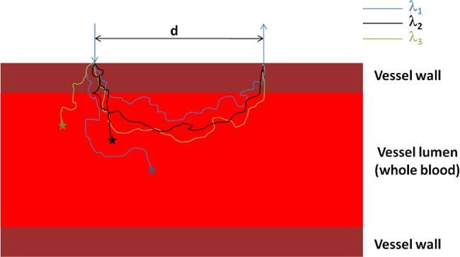
A schematic of the multilayer model mimicking a blood vessel.
Table 1. Diameter and wall thickness of the portal vein [13,27] and hepatic artery [13,28].
| Portal Vein (PV) | Hepatic Artery (HA) | |
|---|---|---|
| Vessel wall thickness (mm) | 0.61 | 0.49 |
| Vessel lumen diameter (mm) | 7.8 | 3.8 |
Table 2. Blood optical properties for two oxygenation states [24,25].
| Oxygenated | Deoxygenated | ||||||
|---|---|---|---|---|---|---|---|
| λ (nm) | µa (1/mm) | µs (1/mm) | g | µa (1/mm) | µs (1/mm) | g | |
| 735 nm | 0.2408 | 80.5 | 0.9790 | 0.6025 | 80.5 | 0.9790 | |
| 805 nm | 0.4557 | 76.7 | 0.9786 | 0.3943 | 76.7 | 0.9786 | |
| 940 nm | 0.6555 | 67.7 | 0.9760 | 0.3744 | 67.7 | 0.9760 | |
For each run, 1 million photon packets were launched in different directions, with equal probability, within the Numerical Aperture (NA) of the source. The program recorded the collected intensity at the tissue surface and the corresponding penetration depth of each photon collected, producing a photon distribution map indicating at every point of the surface how many photons were collected and the penetration depth of each photon. This feature was used to find the probing depth for every source to detector separation and to separate the background intensity collected from photons that are probing the blood.
To study the effect of the source spatial distribution, the collected intensity was convoluted with the source spatial profile as discussed by Wang et al. [29]. All the modeling results were verified by comparison to MCML and CONV developed by Wang et al. [22,29].
2.2. In vitro setup
To verify the modeling results, an in vitro system was constructed to measure perfusion and oxygenation in a liver phantom at different source - detector separations. The phantoms were designed to imitate the case where the sensor is placed on a blood vessel (PV or HA) at the entrance of the liver to monitor the blood supply.
The polydimethylsiloxane (PDMS) based phantom was prepared by mixing 437.4 mg of 0.5-1 μm Al2O3 powder, 120 mg of 100 nm Al2O3 powder, 4.02μL of black India ink (Higgins, Black India 4415), 120 μL of blue food coloring, and 60mL PDMS resin. Long et al. showed that this formula has similar optical properties to liver tissue [30]. The mixture was sonicated and stirred until homogeneously distributed. Then, 6 mL of curing agent was added to the mixture and stirred until uniform. Vacuum was applied to degas bubbles in the mixture. Finally, the mixture was poured into a petri-dish containing a plastic tube (8 mm in outer diameter for the PV or 3 mm for HA) fixed at 1 mm above the petri-dish bottom surface and cured at 65°C to completely crosslink the PDMS. The plastic tube was removed, and the resulting phantom is a slab with the optical properties of liver tissue containing a hollow cylindrical structure with similar dimensions to the vessel under investigation (PV or HA). Slabs of the same material were also fabricated for use in case extra thickness above or below the initial design is needed. Figure 2 shows a schematic of the phantom with the optical probe placed on top of it.
Fig. 2.

A schematic of the PDMS based portal vein phantom showing the placement of the probe on top. The Light Emitting Diode is protruding out of the probe surface to provide better light coupling to the interrogation medium. The source to detector separation is referred to as d.
To avoid handling whole blood that needs to be in a pH and temperature controlled medium, and requires oxygenators and blood analyzers to change and test oxygen levels, we formulated two dye solutions that have optical properties similar to circulating blood in its oxygenated and deoxygenated states [25,26]. To mimic the absorption spectrum of whole blood in its deoxygenated state, we used a mixture of 0.165% v/v India ink (Speedball Art, product number 3338) and 2.67% v/v inkjet photo cyan (Macro Enter, cat.# FPB085) dissolved in Phosphate Buffered Solution (PBS 0.01M, pH 7.4). The India ink has an extinction coefficient that covers all the wavelength bands of interest [31,32] and it was used to create a baseline in the extinction coefficient spectrum that matches the absorption in the near infrared wavelength range. The inkjet photo cyan was used to increase the absorption on the red side of the spectrum, a characteristic of the deoxygenated state of blood. On the other hand, the oxygenated state has a higher absorption in the NIR region and 188.6 mg/L of Epolight 2717 (Epolin, Inc.) was used to increase the absorption in the NIR region along with 0.088% v/v of India ink in a PBS. The extinction coefficient of the two dye solutions compared to that of whole blood is shown in Fig. 3 .
Fig. 3.
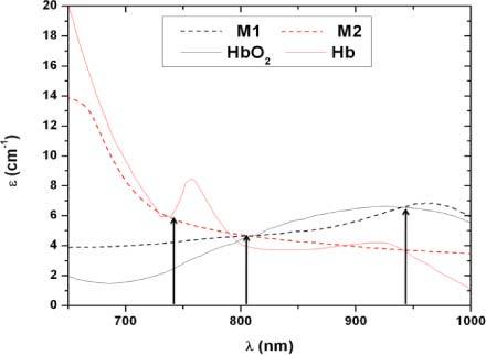
A comparison of the absorption spectra of whole blood and the two dye solutions used in the in vitro setup. M1 is the dye mixture mimicking oxygenated blood and is made of Epolight 2717 and India ink. M2 is made of India ink and inkjet photo cyan to mimic the optical properties of deoxygenated blood. The solid lines show the extinction coefficients of the two oxygenation states of whole blood [25,26].
The extinction coefficient of the dye solutions matches closely to that of whole blood at the three wavelengths of interest (735, 805 and 940 nm). The isobestic point is red shifted when compared to the data reported by Prahl [25], however, there are inconsistencies in the reported isobestic point between different groups and it ranges between 797 nm [25] and 815 nm [33]. Our dye mixtures have an isobestic point, at 807 nm, in between these two extremes. At 735 nm the extinction coefficient of the dye solution M1 does not match exactly that of the oxygenated state of circulating blood. This causes the dynamic range between the two dye solutions at 735 nm to decrease causing the resolution in detecting oxygenation changes to decrease. For the purpose of this paper, this is not problematic since the main goal is to determine the optimal probe design and the same dye solution will be used to compare all of the different designs. At 940 nm, the two solutions match the desired extinction coefficients exactly.
Two peristaltic pumps (Gilson, Minipuls 3) driven using LabVIEW via a data acquisition board (National Instruments, USB 6009) were used to pump the dye solutions through the phantom. Extra care was taken to ensure no air bubbles were circulated. The driver signal used to control the pumps was a square wave. The frequency and the pulse width were set to the desired values that mimic the cardiac pulsatile flow pattern. Each pump can be used to pump a different dye solution corresponding to different oxygenation states and the mixture can mimic any oxygenation state by changing the ratio of the pump speeds.
The probes used are circular (1 inch in diameter) and contain a single can package with four light emitting diodes (epitex, L660/735/805/940-40B42-C-I) and a silicon photodetector (Hamamatsu, S2833-01). Five different LED to photodetector spacings were used ranging from 2 mm to 10 mm (edge to edge separation) with a step of 2 mm. A mechanical arm was used to fix the probe on the surface of the phantom above the hollow cylinder (Fig. 2) with the LED and photodetector aligned along the tube. The three wavelengths are time multiplexed to minimize power consumption and prevent overlap of the optical signal at the photodetector [14]. Figure 4 shows the complete setup with the LabVIEW interface used for data collection and visualization.
Fig. 4.
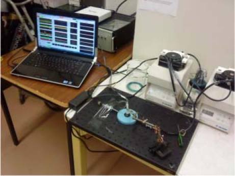
In vitro setup showing the two peristaltic pumps pushing a dye solution through the PV phantom with the optical probe held on top with a mechanical arm. Note the phantom appears light bluish in color to the eye but has the optical properties, in the 735-940 nm wavelength range, of liver.
3. Results
3.1. Monte Carlo modeling results
The diffuse reflection intensity at the surface decayed rapidly with increasing source-detector separation for all three wavelengths, for both simulated oxygenated and de-oxygenated signals. However, these intensities (the case of oxygenated blood is shown in Fig. 5a ) carry signal from the blood volume as well as background intensity from the surrounding tissue. To separate the signal from background intensity, we looked at the difference between the collected intensity in the cases of oxygenated and deoxygenated blood. This difference eliminates the constant background intensity and is a better indicator of the optimal spacing to collect the highest signal probing the blood volume. The difference showed a plateau phase followed by a quick decay for the 735 and 940 nm wavelengths. This plateau extends to 0.55 and 0.45 mm for the 735 and 940 nm wavelengths respectively (Fig. 5b). However, the 805 nm wavelength, since it is near the isobestic point, carried little information about the oxygenation state. Note that the 805 nm wavelength does have a little bias to the 940 nm side, since in our model 805 nm is on the IR side of the isobestic point. After the peak, the difference signal decayed rapidly to reach 10% of its maximal value at 2.4 and 2.2 mm for the 735 and 940 nm wavelengths respectively. Despite the rapid decay, there was still a relatively long range where the signal is strong enough to have a dynamic difference between the two oxygenation states.
Fig. 5.
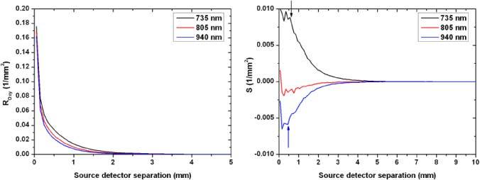
Left panel; Fluence decay curves for all three wavelengths as a function source to detector separation. These curves correspond to the case of oxygenated blood. The curves indicate a rapid decay in total collected fluence with increasing separation. Right panel: the difference (S = ROXY – RDEOXY) as a function of source to detector separation. The signal S shows a plateau phase with a maximal value followed by a rapid decay for the 735 and 940 nm wavelengths. The 805 nm wavelength carries a low oxygenation signal since it was slightly on the IR side of the isobestic point. The arrows indicate the end of the plateau phase and the start of the rapid decay.
In Fig. 5 the signal is presented in terms of its total reflectance at a specific distance (Fig. 5a for oxygenated simulation) and difference between oxygenated and de-oxygenated reflectance (Fig. 5b). However, the overall intensity decays with increasing separation. This implies that, although signal (S) is decaying, the signal to background ratio (SBR) might be constant or even increasing. To validate this hypothesis, we looked at the normalized intensity that we defined as the ratio of signal difference (S) to the total average intensity (It). Equation (1) shows the defined SBR ratio where Roxy and RDeoxy are the photon fluence at the surface in the oxygenated and deoxygenated state respectively.
| (1) |
S is the signal defined as the difference between the collected intensities in the oxygenated and deoxygenated states:
It is the average total intensity in the oxygenated and deoxygenated states:
Note that It is the average total intensity; thus it comprises both signal and background and the defined SBR is the ratio of the difference signal to the total collected intensity which gives an idea about the signal to background ratio.
Figure 6 shows the SBR calculated using (1) as a function of source-detector separation. In the source-detector separation range shown (0.05 to 10 mm) the absolute value of the SBR is monotonically increasing. Past this range, this ratio is very noisy due to the weakness of the collected intensity.
Fig. 6.
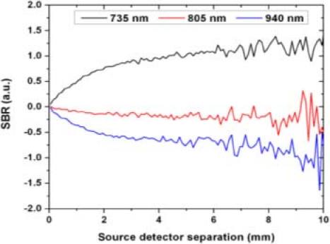
SBR as a function of source to detector separation. SBR starts from 0 and absolute value increases monotonically (Note by definition this means at 735 nm the SBR is positively increasing and at 940 nm the SBR is negatively increasing with separation indicating a decrease in the background to signal ratio. For the 805 nm wavelength, SBR is close to zero with a little bias to the negatively increasing 940 nm side, since in our model 805 nm is on the IR side of the isobestic point.
To better understand this phenomenon, we added to our MC algorithm a feature to record the penetration depth of the collected photons on the tissue surface. As shown in Fig. 7(a) below, although the total intensity decreased, the ratio of photons collected from the vessel lumen (deeper than 0.5 mm which is the vessel upper limit) increased relatively to the photons probing the shallow tissue as we increased the source to detector separation. However, the total number of collected photons probing the blood layer decreased. This supports the data presented in Figs. 5 and 6 and indicates that the total intensity and signal decrease with increasing source to detector separations but the signal to background ratio increases. These findings are very important to know when designing probes for this type of sensor in order to optimize the use of the dynamic range of the photodetector as discussed in further details in section 4.
Fig. 7.
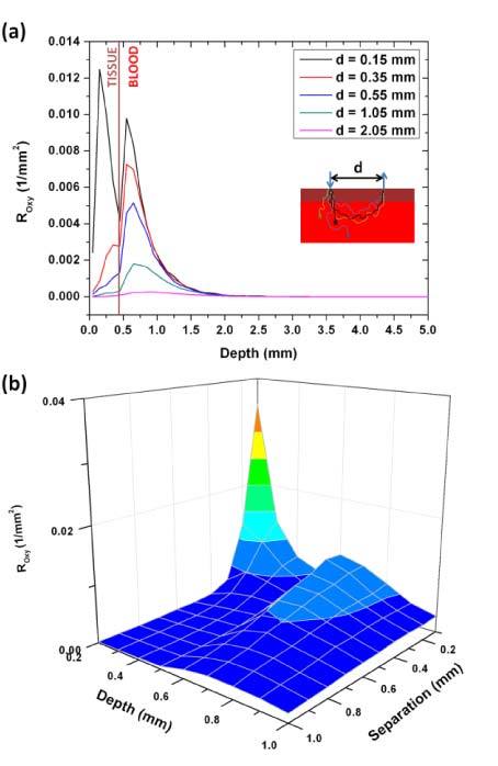
The distribution of the collected photon fluence on the penetration depth for the 735 nm wavelength. Photons with a penetration depth higher than 0.5 mm are considered as signal while those that have a shallower penetration depth are considered as background since they do not probe the blood volume. Panel (a) shows the data for 5 selected source-detector separations. Panel (b) is a 3D representation of the data.
Figure 7(b) shows the collected photon fluence as a function of separation and penetration depth of each photon. This figure shows two peaks before and after the vessel lumen boundary at 0.5 mm. The shallower peak corresponds to the background intensity and, although higher in intensity, decays (as a function of source to detector separation) faster than the second peak that corresponds to the signal collected from the vessel lumen. The axes on this graph start at 0.2 mm (depth) and 0.1 mm (source to detector separation) because before these points there is a high background peak (at 0.1 mm depth and 0.1 mm source to detector separation) that is difficult to visualize with the signal peak on the same scale.
One way to maximize both quantities, SBR and S, if weighted equally is to maximize their product (Eq. (2)). Figure 8 shows the product as a function of source-detector separation.
Fig. 8.
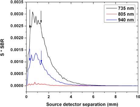
The product of signal (S) and SBR as a function of source to detector separation. The product shows a plateau phase with maximal S*SBR product for the 735 and 940 nm wavelengths. The 805 nm wavelength carries almost no oxygenation signal and the product is stable at nearly zero.
| (2) |
As expected, the 805 nm wavelength carries almost no oxygenation information and the product is stable at nearly zero for all spacings. However, for both the 735 and 940 nm wavelengths, the product starts as an increasing function with source to detector separation and plateaus at 0.35 and 0.45 mm respectively. This plateau ends and a rapid decay starts around 1.25 and 1.35 mm, respectively.
All the previous results were based on a collimated point source. Other probe characteristics such as the source NA and spatial profile might have a significant influence on these findings. The NA effect was studied by launching the photons in different directions, with equal probability, within a cone corresponding to a numerical aperture specified by the user. As expected, the numerical aperture of the source had no significant effect on the results because of the highly scattering nature of tissue.
To investigate the effect of the source spatial profile, we compared the results of the point source to those of a 4.5 mm cylindrical flat beam mimicking the light emitting diodes used in our probes (Epitex, L660/735/805/940-40B42-C-I) and a photodetector with an active area of 2.4 mm x 2.5 mm (Hamamatsu, S2833-01). Figure 9 shows the corresponding results.
Fig. 9.
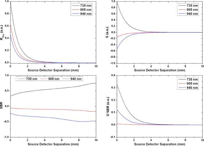
The quantities discussed earlier for a 4.5 mm source and a 2.4 mm x 2.5 mm photodetector. The diffuse reflectance for all three wavelengths was normalized to the reflectance at the closest separation for the 735 nm wavelength. The signal S was normalized similarly.
Similar to the point source case, Fig. 9 shows a rapid decay in the intensity and signal as the detector is moved away from the source. The SBR ratio shows also a similar profile to the previous case with the main difference being the start point that is not equal to zero in that case. This is expected since the broad source can be considered as an assembly of point sources and even when the detector is placed right next to the source there will still be a point source at the other end that is far from the detector and is probing deep in the tissue collecting signal from the blood vessel lumen. Note that the results from the circular flat beam appear less noisy due to the convolution process, used to account for the source spatial profile, which eliminates high frequency noise. This can be thought of as having multiple point sources, instead of one, launching photons leading to a less noisy diffuse reflectance signal. Table 3 summarizes the results presented above.
Table 3. Summary of the modeling resultsa.
|
Point Source |
4.5 mm Beam |
||||||
|---|---|---|---|---|---|---|---|
| Maximum | Plateau Phase | Maximum | Plateau Phase | ||||
| 735 nm | S | 0 | 0–0.55 mm | 0 | x | ||
| SBR | ↗ | > 3.05 mm | ↗ | x | |||
| S*SBR | 0.55 | 0.35–1.25 mm | 0 | x | |||
| 940 nm | S | 0 | 0–0.45 mm | 0 | x | ||
| SBR | ↗ | > 2.55mm | ↗ | x | |||
| S*SBR | 0.85 | 0.45–1.35 mm | 0 | x | |||
a↗ refers to a monotonically increasing function with increasing source-detector separation. The plateau phase refers to ranges of source-detector separations where the corresponding function is changing relatively slow compared to the rest of the source-detector separations.
3.2. In vitro results
To verify the modeling results and apply them to our system, we used the setup described in section 2.2. Five source-detector spacings were used and compared to the model. For each run, one of the two dye solutions corresponding to the two oxygenation states of blood, was passed through the phantom using the flow system previously described. We alternated between the dye solutions to calculate the quantities defined in section 3.1 and the phantom was washed in between runs by flowing deionized water through the fluidics system. This experiment was repeated three times. For each set of experiments, data was collected with the shortest spacing probe first and its position on the phantom was marked to guaranty similar coupling between all probes. Figure 10 shows the signal S, previously defined in Eq. (1), for the in vitro phantom studies compared to the MC modeling results. The data from 3 sets of experiments was averaged. In terms of calibration, the average of the shortest spacing probe was normalized to the model to account for the probe characteristics such as detector sensitivity and LED power, the same calibration factor was applied to the rest of the probes. Since the 805 nm wavelength carries minimal information about changes in the dye solution (i.e. simulated oxygenation), it was used as a baseline to account for any changes not related to varying the dye solution as shown in Eq. (3). In the ideal case, where there are no changes in the background, the intensity on the 805 nm wavelength is the same for both dye solutions and Eq. (3) reduces to (IOxy - IDeoxy). In this case, IOxy and IDeoxy are the collected intensity at the wavelength of interest when the phantom is perfused with the dye solution mimicking oxygenated and deoxygenated blood, respectively:
Fig. 10.
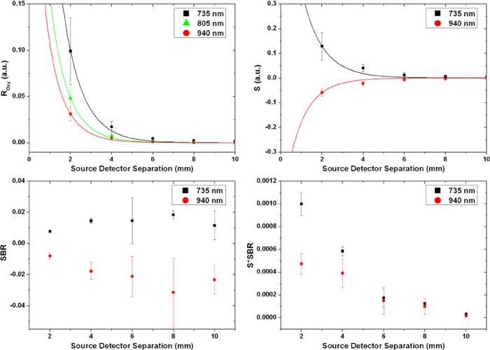
In vitro data collected from the PDMS based phantom perfused with the dye solutions. The solid lines show the data from the MC model while the squares and circles represent the average of the collected data from the phantom at the 735 and 940 nm wavelengths respectively. The error bars correspond to ± one standard deviation.
| (3) |
4. Discussion
The probing depth in diffuse reflection is highly dependent on the source to detector separation. Large separations lead to deeper probing which increases the blood signal carrying portion of the total intensity. However, this increases the optical path length and attenuates the total intensity causing lower levels of light to be collected which leads to higher system error. Photodetectors and electronic amplifiers have a limited dynamic range, and optimizing the separation is critical to increase the levels of the signal without saturating the detection electronics with background intensity. Using higher separations lead to better signal to background ratios (less sample noise) but at the same time it decreases the intensity of the collected light leading to a decrease in the system signal to noise ratio assuming fixed electronics noise. A compromise has to be made between the signal to background ratio and the absolute values of the collected intensity and signal. Our model showed that, for a point source, there is an optimal range with high signal levels and high signal to background ratio for both wavelengths (735 and 940 nm) extending from 0.45 to 1.25 mm. These values change with the spatial profile of the source. For the case of a 4.5 mm LED, most of this plateau phase overlapped with the source and only a peak was seen right next to the source followed by a signal decay. Despite this decay, the collected signal is high enough to be detected millimeters away from the source. This was shown in our in vitro data (Fig. 10) where changes in oxygenation were still detected 10 mm away from the edge of the source. The previously defined SBR ratio showed a similar increasing trend for the in vitro data. However, past 6-8 mm edge to edge separation the ratio showed a decreasing trend that is due to the system noise since the total intensity at this point is close to the detection limit of our hardware. Note that the same amplification level was used for all separations to provide a fair comparison. The numbers for the SBR ratio from the in vitro data are much lower than those calculated by the model due to multiple reasons. The main reason for this discrepancy results from the use of a simplified 2D layered model with the blood vessel represented as a layer of blood. In the real case, the blood vessel is surrounded by tissue that contributes to the background intensity and not the oxygenation signal. Also, the dynamic range between the optical properties of the two dye mixtures mimicking the two oxygenation states is less than that of whole blood which causes a reduction in the signal (S) intensity. However, this second factor is not as significant as the first since the optical properties of the dye mixtures at the 940 nm wavelength match those of whole blood very closely and the reduction in the SBR ratio can still be seen. As expected, similar to the modeling results, the product S*SBR also showed a decreasing trend for the in vitro data. This shows that the optimal performance of this source-detector pair is at the closest separation.
To better understand this tradeoff between signal levels and the signal to background ratio, we ran simulations for different oxygenation levels and observed the correlation between the photon fluence values and the oxygenation levels as shown in Figs. 11(a)-(c) . For very short separations, the coefficient of determination, R2, started as an increasing function and peaked at 0.45 mm separation with a peak value of 0.9941. Past this point, R2 showed a decreasing trend and reached 0.9795 (0.7022) at 1.05 mm (10.05 mm) separation. As for the slope of the linear fit, it showed a similar trend with increasing source-detector separation as the signal S which was expected (Fig. 11(d)).
Fig. 11.
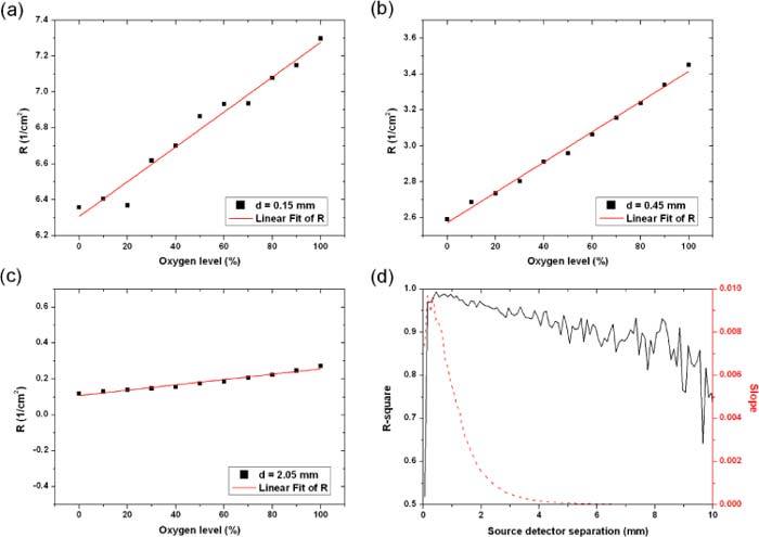
The change in photon fluence at the surface of the tissue with changing oxygenation levels. The three panels (a)-(c) correspond to three different source-detector spacings indicated in the inset legends. At 0.45 mm separation, the change in diffuse reflection correlates well with the oxygenation changes (R2 = 0.994) and the slope of the linear fit is high (0.00844) indicating a good sensitivity to oxygenation changes. Panel (d) shows the changes of the R2 factor and the slope as a function of the source to detector separation.
The coefficient R2 shows that, although the slope representing the signal level is highest for the shortest separation (Fig. 11(d)), the optimal spacing where the signal correlates best with changes in the vessel lumen is at 0.45 mm. This is shown in Figs. 11(a)-(c) where the slope and intensity values are the highest in panel (a) (d = 0.15 mm) while the photon fluence doesn’t correlate with oxygenation as closely as in the top right panel (d = 0.45 mm).
Although the principle we used in optimizing the source-detector separation relies on changing the oxygen saturation of the blood and monitoring its effect on the collected diffuse reflectance, the results stand true for any change in the optical properties of the blood whether they were due to oxygenation, perfusion or hematocrit variations.
As mentioned earlier in the introduction, this sensor can be used to monitor perfusion and oxygenation in many other visceral organs. Since the optimal source-detector separation is a function of the optical properties and the dimensions of the vessel under investigation, the results presented in this paper stand true only for the case of the portal vein. However, the same methods employed in this manuscript can be used to define the optimal source-detector separation for similar applications.
5. Conclusions
Source to detector separation is a major factor in optimizing the performance of any diffuse reflectance based optical sensor. This becomes more important in the case of implantable biosensors where power consumption is of significant concern. In this work, we modeled the performance of an implantable perfusion and oxygenation sensor and found a source-detector separation of around 0.5 mm to be optimal in the case of a point source. Closer placement of the detector yields very high background intensity while moving the detector further than 1.2 mm shows a rapid decay in total intensity and signal levels. For the more realistic case of a 4.5 mm diameter LED package and a 2.4 mm x 2.5 mm photodetector, it was shown that the highest signal is collected with the source and detector placed right next to each other. However, similar to the point source case, it was shown that larger separations lead to higher SBR.
The results were compared to data collected from in vitro phantom studies. We reported a dye solution mimicking the absorption properties of the two oxygenation states of blood. These mixtures can be useful in characterizing and testing any optical sensor that probes blood. We used these mixtures to perfuse a phantom mimicking the optical and anatomical properties of the portal vein and the results were used to verify our modeling data. The in vitro data showed similar trends to those of the MC model with some contribution from the system/hardware noise that caused the SBR ratio to show a decreasing trend past 6-8 mm source-detector separation.
Acknowledgments
This research was funded by a bioengineering research partnership (BRP) grant from NIH, (#5R01-GM077150). The data and analyses reported in the 2009 Annual Report of the U.S. Organ Procurement and Transplantation Network and the Scientific Registry of Transplant Recipients have been supplied by UNOS and Arbor Research under contract with HHS/HRSA. The authors alone are responsible for reporting and interpreting these data; the views expressed herein are those of the authors and not necessarily those of the U.S. Government. The authors would like to thank Travis King, M.S. student in the Optical Biosensing Laboratory, for his helpful discussions.
References and links
- 1.U.S. Organ Procurement and Transplantation Network and the Scientific Registry of Transplant Recipients, “2009 OPTN/SRTR Annual Report: Transplant Data 1999-2008,” U.S. Department of Health and Human Services, Health Resources and Services Administration, Healthcare Systems Bureau, Division of Transplantation, Rockville, MD.
- 2.Humeau A., Steenbergen W., Nilsson H., Strömberg T., “Laser Doppler perfusion monitoring and imaging: novel approaches,” Med. Biol. Eng. Comput. 45(5), 421–435 (2007). 10.1007/s11517-007-0170-5 [DOI] [PubMed] [Google Scholar]
- 3.Kok T., Slooff M. J. H., Thijn C. J. P., Peeters P. M. J. G., Verwer R., Bijleveld C. M. A., van den Berg A. P., Haagsma E. B., Klompmaker I. J., “Routine Doppler ultrasound for the detection of clinically unsuspected vascular complications in the early postoperative phase after orthotopic liver transplantation,” Transpl. Int. 11(4), 272–276 (1998). 10.1111/j.1432-2277.1998.tb00969.x [DOI] [PubMed] [Google Scholar]
- 4.Vajkoczy P., Roth H., Horn P., Lucke T., Thomé C., Hubner U., Martin G. T., Zappletal C., Klar E., Schilling L., Schmiedek P., “Continuous monitoring of regional cerebral blood flow: experimental and clinical validation of a novel thermal diffusion microprobe,” J. Neurosurg. 93(2), 265–274 (2000). 10.3171/jns.2000.93.2.0265 [DOI] [PubMed] [Google Scholar]
- 5.Khot M. B., Maitz P. K., Phillips B. R., Bowman H. F., Pribaz J. J., Orgill D. P., “Thermal diffusion probe analysis of perfusion changes in vascular occlusions of rabbit pedicle flaps,” Plast. Reconstr. Surg. 115(4), 1103–1109 (2005). 10.1097/01.PRS.0000156546.45229.84 [DOI] [PubMed] [Google Scholar]
- 6.Bowman H. F., Balasubramaniam T. A., “A new technique utilizing thermistor probes for the measurement of thermal properties of biomaterials,” Cryobiology 13(5), 572–580 (1976). 10.1016/0011-2240(76)90150-4 [DOI] [PubMed] [Google Scholar]
- 7.Ricciardi R., Schaffer B. K., Kim R. D., Shah S. A., Donohue S. E., Wheeler S. M., Quarfordt S. H., Callery M. P., Meyers W. C., Chari R. S., “Protective effects of ischemic preconditioning on the cold-preserved liver are tyrosine kinase dependent,” Transplantation 72(3), 406–412 (2001). 10.1097/00007890-200108150-00008 [DOI] [PubMed] [Google Scholar]
- 8.Klar E., Kraus T., Bleyl J., Newman W. H., Bowman H. F., Hofmann W. J., Kummer R., Bredt M., Herfarth C., “Thermodiffusion for continuous quantification of hepatic microcirculation--validation and potential in liver transplantation,” Microvasc. Res. 58(2), 156–166 (1999). 10.1006/mvre.1999.2166 [DOI] [PubMed] [Google Scholar]
- 9.J. G. Webster, Design of Pulse Oximeters, Medical Science Series (Institute of Physics Pub., Bristol; Philadelphia, 1997), p. xvi. [Google Scholar]
- 10.Aoyagi T., “Pulse oximetry: its invention, theory, and future,” J. Anesth. 17(4), 259–266 (2003). 10.1007/s00540-003-0192-6 [DOI] [PubMed] [Google Scholar]
- 11.Reichelt S., Fiala J., Werber A., Förster K., Heilmann C., Klemm R., Zappe H., “Development of an implantable pulse oximeter,” IEEE Trans. Biomed. Eng. 55(2), 581–588 (2008). 10.1109/TBME.2007.902242 [DOI] [PubMed] [Google Scholar]
- 12.A. C. Guyton, Textbook of Medical Physiology, 8th ed. (Saunders, Philadelphia, 1991), p. xli. [Google Scholar]
- 13.Tziafalia C., Vlychou M., Tepetes K., Kelekis N., Fezoulidis I. V., “Echo-Doppler measurements of portal vein and hepatic artery in asymptomatic patients with hepatitis B virus and healthy adults,” J. Gastrointestin. Liver Dis. 15(4), 343–346 (2006). [PubMed] [Google Scholar]
- 14.Ericson M. N., Wilson M. A., Coté G. L., Baba J. S., Xu W., Bobrek M., Britton C. L., Hileman M. S., Moore M. R., Emery M. S., Lenarduzzi R., “Implantable sensor for blood flow monitoring after transplant surgery,” Minim. Invasive Ther. Allied Technol. 13(2), 87–94 (2004). 10.1080/13645700410027866 [DOI] [PubMed] [Google Scholar]
- 15.Ericson M. N., Wilson M., Cote G., Britton C. L., Xu W., Baba J., Bobrek M., Hileman M., Moore M., Frank S., “Development of an implantable oximetry-based organ perfusion sensor,” Conf. Proc. IEEE Eng. Med. Biol. Soc. 3, 2235–2238 (2004). [DOI] [PubMed] [Google Scholar]
- 16.Subramanian H., Ibey B. L., Xu W. J., Wilson M. A., Ericson M. N., Coté G. L., “Real-time separation of perfusion and oxygenation signals for an implantable sensor using adaptive filtering,” IEEE Trans. Biomed. Eng. 52(12), 2016–2023 (2005). 10.1109/TBME.2005.857667 [DOI] [PubMed] [Google Scholar]
- 17.Reuss J. L., Siker D., “The pulse in reflectance pulse oximetry: modeling and experimental studies,” J. Clin. Monit. Comput. 18(4), 289–299 (2004). 10.1007/s10877-005-2909-6 [DOI] [PubMed] [Google Scholar]
- 18.Reuss J. L., “Multilayer modeling of reflectance pulse oximetry,” IEEE Trans. Biomed. Eng. 52(2), 153–159 (2005). 10.1109/TBME.2004.840188 [DOI] [PubMed] [Google Scholar]
- 19.Hickey M., Kyriacou P. A., “Optimal spacing between transmitting and receiving optical fibres in reflectance pulse oximetry,” J. Phys. Conf. Ser. 85, 012030 (2007). 10.1088/1742-6596/85/1/012030 [DOI] [Google Scholar]
- 20.J. L. Reuss, “Arterial pulsatility and the modeling of reflectance pulse oximetry,” in Proceedings of the 25th Annual International Conference of the IEEE Engineering in Medicine and Biology Society, 2003 (IEEE, 2003), pp. 2791–2794. [Google Scholar]
- 21.Akl T. J., King T. J., Long R., Baba J. S., McShane M. J., Ericson M. N., Wilson M. A., Cote G. L., ““Optimizing source detector separation for an implantable perfusion and oxygenation sensor,”,” Proc. SPIE 7906, 790605–, 790605-5. (2011). 10.1117/12.875731 [DOI] [PMC free article] [PubMed] [Google Scholar]
- 22.Wang L. H., Jacques S. L., Zheng L. Q., “MCML--Monte Carlo modeling of light transport in multi-layered tissues,” Comput. Methods Programs Biomed. 47(2), 131–146 (1995). 10.1016/0169-2607(95)01640-F [DOI] [PubMed] [Google Scholar]
- 23.Ritz J.-P., Roggan A., Isbert C., Müller G., Buhr H. J., Germer C.-T., “Optical properties of native and coagulated porcine liver tissue between 400 and 2400 nm,” Lasers Surg. Med. 29(3), 205–212 (2001). 10.1002/lsm.1134 [DOI] [PubMed] [Google Scholar]
- 24.Friebel M., Helfmann J., Netz U., Meinke M., “Influence of oxygen saturation on the optical scattering properties of human red blood cells in the spectral range 250 to 2,000 nm,” J. Biomed. Opt. 14(3), 034001 (2009). 10.1117/1.3127200 [DOI] [PubMed] [Google Scholar]
- 25.S. Prahl, “Optical absorption of hemoglobin” (www.omlc.org, 1999), retrieved January 20, 2011, http://omlc.ogi.edu/spectra/hemoglobin/
- 26.Faber D. J., Aalders M. C. G., Mik E. G., Hooper B. A., van Gemert M. J. C., van Leeuwen T. G., “Oxygen saturation-dependent absorption and scattering of blood,” Phys. Rev. Lett. 93(2), 028102 (2004). 10.1103/PhysRevLett.93.028102 [DOI] [PubMed] [Google Scholar]
- 27.Wang P. J., Li W. C., Xi G. M., Wang H. Q., Zhang Z. H., Yao B. C., Tang W., Deng Z. H., Zhang X. H., “Biomechanical study of hepatic portal vein in humans and pigs and its value in liver transplantation,” Transplant. Proc. 41(5), 1906–1910 (2009). 10.1016/j.transproceed.2008.10.097 [DOI] [PubMed] [Google Scholar]
- 28.Avolio A. P., “Multi-branched model of the human arterial system,” Med. Biol. Eng. Comput. 18(6), 709–718 (1980). 10.1007/BF02441895 [DOI] [PubMed] [Google Scholar]
- 29.Wang L., Jacques S. L., Zheng L., “CONV--convolution for responses to a finite diameter photon beam incident on multi-layered tissues,” Comput. Methods Programs Biomed. 54(3), 141–150 (1997). 10.1016/S0169-2607(97)00021-7 [DOI] [PubMed] [Google Scholar]
- 30.Long R., King T., Akl T., Ericson M. N., Wilson M. A., Coté G. L., McShane M. J., “Opto-fluidic phantom mimicking optical properties of porcine livers,” Biomed. Opt. Express 2(7), 1877–1892 (2011). 10.1364/BOE.2.001877 [DOI] [PMC free article] [PubMed] [Google Scholar]
- 31.Di Ninni P., Martelli F., Zaccanti G., “The use of India ink in tissue-simulating phantoms,” Opt. Express 18(26), 26854–26865 (2010). 10.1364/OE.18.026854 [DOI] [PubMed] [Google Scholar]
- 32.Madsen S. J., Patterson M. S., Wilson B. C., “The use of India ink as an optical absorber in tissue-simulating phantoms,” Phys. Med. Biol. 37(4), 985–993 (1992). 10.1088/0031-9155/37/4/012 [DOI] [PubMed] [Google Scholar]
- 33.Takatani S., Graham M. D., “Theoretical analysis of diffuse reflectance from a two-layer tissue model,” IEEE Trans. Biomed. Eng. BME-26(12), 656–664 (1979). 10.1109/TBME.1979.326455 [DOI] [PubMed] [Google Scholar]


