Abstract
We developed a piezoelectric-transducer- (PZT) based miniature catheter with an outer diameter of 3.5 mm for ultrahigh-speed endoscopic optical coherence tomography (OCT). A miniaturized PZT bender actuates a fiber and the beam is scanned through a GRIN lens and micro-prism to provide high-speed, side-viewing capability. The probe optics can be pulled back over a long distance to acquire three-dimensional (3D) data sets covering a large area. Imaging is performed with 11 μm axial resolution in air (8 μm in tissue) and 20 μm transverse resolution, at 960 frames per second with a Fourier domain mode-locked laser operating at 480 kHz axial scan rate. Using a high-speed data acquisition system, endoscopic OCT imaging of the rabbit esophagus and colon in vivo and human colon specimens ex vivo is demonstrated.
OCIS codes: (170.4500) Optical coherence tomography, (170.3880) Medical and biological imaging, (170.2150) Endoscopic imaging, (170.2680) Gastrointestinal, (140.3600) Three-dimensional image acquisition, (110.2350) Fiber optics imaging, (120.5800) Scanner, (120.3890) Medical optics instrumentation
1. Introduction
Optical coherence tomography (OCT) performs micrometer-scale, cross-sectional and three-dimensional imaging by measuring the echo time delay of backscattered light [1]. Internal body imaging was enabled by the development of fiber-optic-based OCT endoscopes [2,3]. In vivo endoscopic OCT imaging is challenging because fast optical scanning must be implemented inside a miniaturized imaging probe. Many scanning mechanisms have been realized in catheter-based endoscopic OCT systems, such as rotating a fiber micro-prism module at the proximal end [2,4–6], swinging the distal fiber tip by a galvanometric plate [7], swinging the fiber on a cantilever by piezoelectric actuators [8,9], and scanning the beam using microelectromechenical systems [10–13]. Although these endoscopic OCT imaging techniques can potentially achieve very high imaging speed, to date, no methods have been demonstrated for imaging over 100 fps because of hardware limitations, such as the speed of rotation for the optics or limitations in the OCT acquisition rate. Recently, record imaging speeds have been demonstrated in a microscopy system using multiple scanning spots in a custom designed multibeam scan head with traditional x-y galvanometer scanning methods and a buffered Fourier domain mode-locked (FDML) laser source [14]. Ultrafast imaging speeds have not yet been demonstrated endoscopically.
In this paper we demonstrate a piezoelectric-transducer- (PZT) based miniature catheter with an outer diameter of 3.5 mm for ultrahigh-speed endoscopic OCT imaging. The combination of a miniaturized PZT bender and cantilever fiber has the advantage of large deflection with low driving voltage, ease of adjustment of the scanning frequency, and flexibility to implement slow scan methods to achieve three-dimensional imaging. The side-viewing probe can be pulled back over a long distance to acquire three-dimensional (3D) data sets covering a large area on the specimen. A 480 kHz axial scan rate from an FDML laser provides high frame rate while maintaining sufficient lines per frame. Using a high-speed data acquisition system, ultrahigh-speed endoscopic OCT imaging can be achieved, and large volume data sets can be acquired in a few second acquisition times.
2. Methods
2.1. Swept Source-OCT imaging system
Figure 1 shows the OCT system used for this experiment. A portion of the laser output was coupled to a Mach-Zehnder interferometer (MZI) to produce interference fringes with zero crossings evenly spaced in frequency. The MZI was set to a delay of 1 mm path difference and fringes were detected by a 200 MHz bandwidth dual-balanced photodetector (Thorlabs, Inc.) to generate the phase information to recalibrate the OCT interference fringe signals. The OCT system consisted of a dual-balanced Michelson interferometer with a pair of optical circulators and a 50/50 fiber-optic splitter (AC Photonics, Inc.) [4,15]. The OCT signal was acquired with the same dual-balanced photodetector with 200 MHz bandwidth (Thorlabs, Inc.). To enable the preview of the acquired images in real time, the calibration MZI interference fringes were acquired once prior to the acquisition of the OCT signal and the acquired OCT signal was recalibrated by the set of the calibration signal. The calibration and OCT signals were digitized using a high-speed A/D card (Innovative Integration, Inc.). The catheter was housed in a transparent fluorinated ethylene propylene (FEP) sheath (Zeus, Inc.) and pulled back with a motorized translation stage (Klinger Scientific, Inc.) at its proximal end to acquire volumetric data. In this study, a pullback speed of 2 mm/s was used while acquiring the 3D-OCT data sets. The power on the sample was about 15 mW.
Fig. 1.
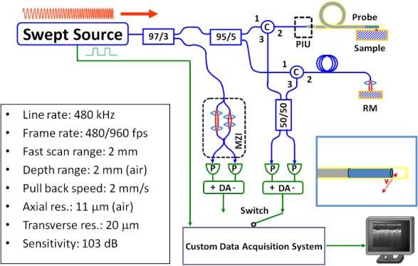
Schematic of swept source OCT system (optics, blue; electronics, green) and a summary of the system performance. The inset showing the catheter indicates the lateral scanning direction of the focused spot. C, circulator; MZI, Mach-Zehnder interferometer; RM, reference mirror; DA, differential amplifier; P, photodetector; PIU, patient interface unit.
2.2. FDML laser operating at 480 kHz axial scan rate
Figure 2 (a) shows a schematic diagram of the triple-buffered FDML laser. The laser has a ring resonator geometry with two optical isolators (AC Photonics, Inc.), a semiconductor optical amplifier (SOA, Covega, Inc.) gain medium and a fiber Fabry-Perot tunable filter (FFP-TF, Lambda Quest, Inc.). The FFP-TF is driven with a sinusoidal waveform at 59.8 kHz, synchronous to the optical round-trip time of the 3,436 m long cavity. Two copies of the backward sweeps, sweeping from long wavelength to short wavelength, are extracted at evenly spaced points within the cavity using 80/20 and 70/30 fiber-optic splitters. These copies are again split, copied, time delayed by 4 μs, and recombined in the external buffering stage. To achieve an effective sweep rate of 480 kHz, an additional external buffering stage is added to again double the effective sweep rate of the FDML laser. The laser output is amplified with a second SOA (Covega, Inc.) outside the cavity, which serves as a booster amplifier. The FFP-TF has a free spectral range (FSR) of 160 nm centered at 1,310 nm and finesse of 1,000. The average output power of the laser after the booster was 40 mW. Figure 2 (b) shows the output spectra of the FDML laser. The central wavelength is ~1315 nm. The total tuning range of the spectrum is 150 nm, with an 80 nm full width at half-maximum (FWHM). Figure 2 (c) shows the instantaneous fringe trace from a Mach-Zehnder interferometer. The duty cycle is almost 100% with a ~2 μs sweep duration, and the seven sweep copies are almost identical.
Fig. 2.
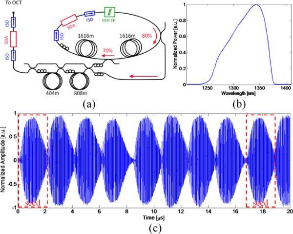
(a) Schematic of the 480 kHz triple-buffered FDML laser. (b) Optical spectrum of the laser. (c) Interferometric trace of the 480 kHz laser from the Mach-Zehnder interferometer. The sweeps indicated by “seed” were generated from the laser cavity. ISO, optical isolator; FFP‑TF, fiber-optic Fabry-Perot tunable filter; SOA, semiconductor optical amplifier
2.3. PZT-based imaging catheter
Figure 3 (a) shows the schematic diagram of the PZT-based catheter design. A tapered 15 mm PZT bender (Piezo Systems, Inc.) was used to deflect the fiber. UV cured epoxy was used to fix the fiber at the distal end of the PZT bender to support the cantilever vibration. A drop of epoxy (~40 mg) was fixed on the fiber tip to reduce the resonant frequency of the fiber cantilever to ~500 Hz. The fiber tip was angle cleaved at 8 degrees to reduce backreflection. The scanning fiber tip is imaged onto the tissue with a GRIN lens of 0.25 pitch (Newport, Inc.). The working distance and the focus spot size are adjustable by changing the distance between the fiber tip and the GRIN lens. In the prototype probe, the working distance was set to be 500 μm in tissue. A micro-prism (Tower Optical, Inc.) was glued on the distal end of the GRIN lens to reflect the laser beam to the side. The focused spot size (FWHM of intensity) is 20 μm, corresponding to ~23 μm in tissue. The lateral scanning range of the imaging beam is about 2 mm with the PZT bender driven with a voltage of 10 V (peak to peak) at a frequency of 480 Hz. A thin holder is used to fix the PZT bender to a 2 mm outer diameter torque coil (Asahi Intecc, Inc.). The torque coil can be pulled back uniformly by a translation stage at the proximal end of the catheter. Figure 3 (b) shows the photo of the probe with outer diameter of 3.5 mm. The total length of the torque coil and sheath for the prototype probe was 1 meter.
Fig. 3.
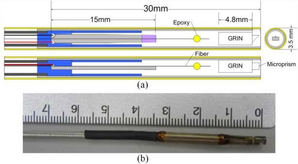
(a) Schematic diagrams of the PZT probe and (b) the photo of the prototype probe.
2.4.High-speed and large volume data acquisition
The ultrahigh-speed OCT imaging system can acquire large data sets with only a few-second acquisition times. In order to support data sets larger than the 4 Gigabyte, the instrument control computer used a 64 bit operation system. The high-speed A/D card (Innovative Integration, Inc.) can sample up to 400 MSPS at 14 bit resolution. Customized user interface and data acquisition software were developed in C++ to coordinate instrument control and enable user interaction. Improved imaging performance was obtained by modifying a commercially available 350 MHz InGaAs dual balanced detector (Thorlabs, Inc.) to increase the transimpedance gain by ~2× to 2.4 kΩ and reduce the bandwidth to 200 MHz [16]. The imaging system thus can acquire OCT data for over 15 seconds at 480 kHz axial scan rate or 960 frames per second with 500 lines per frame.
2.5. Signal processing of the OCT images
The MZI calibration traces were acquired in the beginning of each imaging session and used to calibrate all of the OCT data for that session. Calibration traces were not required for each axial scan sweep. Each MZI sweep contains 832 A/D sample points. The acquired MZI traces were first fast Fourier transformed (FFT), zero-padded to 2,048 points, and then inverse Fourier transformed (IFFT) to obtain an interpolated frequency sweep. The interpolated MZI traces were then Hilbert transformed to obtain the phase of the frequency sweep. The phase information was then used to resample the OCT interference traces from constant time intervals to linear phase, or equal frequency interval samples. Similar to the MZI traces, the OCT traces were interpolated to 2,048 points/sweep using the FFT/zero-padding/IFFT method, and then re-sampled using cubic-spline interpolation to linear phase using the phase calibration information from the MZI traces. The re-sampled OCT traces were then Fourier transformed (FFT) to obtain the axial point spread functions. The axial scans consisted of ~400 samples, spaced by ~5.7 μm with a maximum imaging range of 2.3 mm in air.
3. Results
3.1. System performance
To characterize the sensitivity of the imaging system, a calibrated −54 dB reflection was used in the sample arm. The reference arm power was set to 150–200 microwatts. The sensitivity was measured as the ratio of the peaks of the PSFs to the standard deviation of the noise floor, which was measured with the sample arm blocked. The estimated system losses were ~3 dB arising from losses in the optics, mirror reflectivity, and backcoupling. The measured sensitivity values are not adjusted for these losses. Figure 4 shows the sensitivity roll off and the point spread function from a fixed reflection. The measured sensitivity of the system is 103 dB with 11 μm axial resolution in air (8 μm in tissue) and 2.3 mm imaging depth range in air (1.7 mm in tissue). The sensitivity rolls off ~7.5 dB at imaging depth of 2.25 mm, and the R-number is 2.93 mm/dB, which was calculated from the inverse decay constant of the exponential decay curve fitted to the signal maxima of the linear PSFs [17].
Fig. 4.
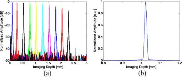
(a) Sensitivity roll-off and (b) point spread function at imaging depth around 1 mm from the ultrahigh-speed endoscopic OCT system.
In order to achieve large scanning range using low operation voltage, the catheter was operated at a frequency close to the resonance of the fiber cantilever, which is proportional to the inverse square of the cantilever length [9,18]. The resonant frequency of a cantilever with a round cross section is [18]
| (1) |
where L and R are the length and radius of the cantilever, respectively; E and ρ are the Young’s modulus and the mass density, respectively; and β is a constant determined by the vibration mode number and boundary condition of the cantilever. For the zeroth-order vibration mode, β = 3.52 [18]. Figure 5 (a) shows the resonant frequency of the fiber cantilever with different cantilever lengths. For the target operating frequency of ~500 Hz, a cantilever length of ~15 mm is required using an uncoated fiber and ~33 mm using a coated fiber, which makes the rigid length of the catheter too long and not practical for use in an endoscope. In this study, we chose the cantilever length as 8 mm using an uncoated fiber; so the rigid length of the catheter is ~30 mm. By adding weight at the cantilever tip, the resonant frequency can be decreased [19]. Figure 5 (b) shows the change of the resonant frequency of the 8 mm fiber cantilever with different epoxy weight on the fiber. With no weight, the resonant frequency is ~1 kHz. The resonant frequency can be reduced to 500 Hz by loading with a mass of 40 mg and to lower than 200 Hz using a mass of 200 mg. Therefore, this method enables a shorter cantilever length with adjustable operation frequency and the catheter can provide sufficient scanning range at low operating voltages necessary for electrical safety in medical applications [20]. In the prototype probe, the current is ~3 μA with a drive voltage of 10 V (peak to peak), both of which are lower than the 42 V or 10 μA safety requirement for direct cardiac application devices defined in the International Standard [20].
Fig. 5.
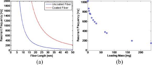
(a) Resonant frequency of the fiber cantilever, versus cantilever length. (b) The resonant frequency of an 8 mm fiber cantilever versus the weight of loading mass applied on the fiber.
The PZT scanner was driven sinusoidally, so the pixels are denser on the edge of the B-scan owing to the slower scanning speed. Hence the B-scan images were converted from sinusoidal transverse scan to linear transverse scan by re-mapping the axial scan positions along the PZT scanning direction. The scan length of the sine was 2 mm, so that spacing between axial scans was 6.3 μm in the center of the scan and decreased to zero near the edges of the scan where the sine reverses direction. The axial scans were averaged near the edges and cubic-spline interpolated in the center portion of the image. The number of axial scans per frame was kept the same as the number of axial scans in the original frame. The pullback speed was 2 mm/sec so that spacing of axial scans in the pullback direction was 2.1 μm.
3.2. In vivo rabbit gastrointestinal imaging
To demonstrate the ability to image microscopic structures in the gastrointestinal tract, in vivo volumetric 3D-OCT data sets of the rabbit esophagus and colon were acquired. These studies were performed under a protocol approved by the Committee on Animal Care (CAC) at MIT. Figure 6 shows a 3D-OCT data set from the esophagus of a female New Zealand White rabbit. The ultrahigh-speed imaging system enables the acquisition of very large data sets which cover long segments of tissue with dense spatial sampling. In this data set, 9,600 frames of 500 axial scans were acquired in 10 seconds, covering a volume size of 2 mm × 20 mm × 1.7 mm (x-y-z) in the rabbit esophagus. The OCT images (Figs. 6 (a)-(c)) allow visualization of the normal esophageal layers including the epithelium (EP), the lamina propria (LP), the muscularis mucosa (MM), the submucosa (SM), the circular muscle (Ci), and the longitudinal muscle (LM). The OCT images correlate well with representative histology of the rabbit esophagus (Fig. 6 (d)). The volumetric data set can be processed and displayed in three dimensions. Figures 6 (e) and (f) show the en face view and cross-sectional view along the pullback direction, respectively. The en face view (Fig. 6 (e)) shows features such as vessels over a large field of view. Vessels have structures similar to dilated glands in the cross-sectional views, but can be distinguished when examining the en face images. Due to the ultrahigh frame rate, the data set can be sampled with a high spatial density and still cover a large field of view. The cross-sectional images (Fig. 6 (f)) provide structural information over a very long region of the esophagus, with enhanced imaging contrast due to dense sampling along the pull-back direction. Figures 6 (g) and (h) show the enlarged view of the regions marked with red and orange boxes in Fig. 6 (e). With the large field of view, the data set can provide comprehensive structural information from different regions in the esophagus.
Fig. 6.
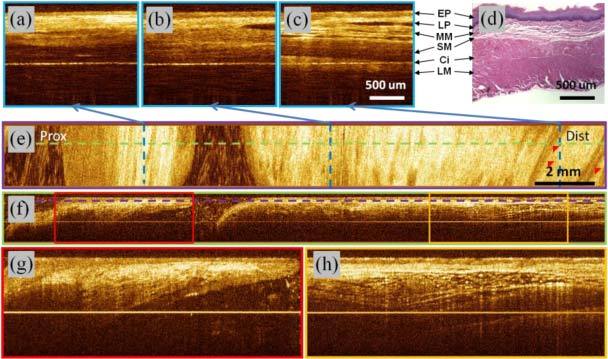
In vivo volumetric OCT images from rabbit esophagus. (a)-(c) A series of cross-sectional images along the fast-scan direction at different locations. (d) Representative histology of the rabbit esophagus. (e) En face image at imaging depth of 160 μm. (f) Cross-sectional image along the pullback direction. (g)-(h) Enlarged views in (f). Red arrows: vessels.
Figure 7 shows a 3D-OCT data set from the colon of a female New Zealand White rabbit. The OCT images (Fig. 7 (a)) allow visualization of the colonic layers including the colonicmucosa (CM), the lamina propria (LP), the muscularis mucosa (MM), the submucosa (SM), the circular muscle (Ci), and the longitudinal muscle (LM), which correlate well with representative histology of the rabbit colon in Fig. 7 (c). The en face view at a depth of 250 μm (Fig. 7 (d)) shows the crypt structures in the rabbit colon. In comparison with human tissue, crypts in the rabbit colon are smaller (~50 μm) and more tightly packed. Crypts in the rabbit colon are often separated by only a few micrometers of lamina propria, usually making it difficult to identify single crypts in the en face images. Nevertheless, the crypts are visible in the enlarged en face view shown in Fig. 7 (e), which correlates well with representative en face histology (Fig. 7 (f)). The ultrahigh-speed imaging also makes 3D-OCT acquisition less sensitive to vibration or motion. Fig. 7 (g) shows the cross-sectional image along the pullback direction. Motion artifacts were relatively small throughout the pullback procedure. Therefore, requirements for image post processing, such as frame alignment can be reduced.
Fig. 7.
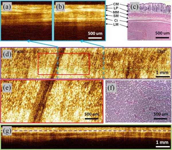
In vivo volumetric OCT images from rabbit colon. (a)-(b) A series of cross-sectional images along the fast-scan direction at different locations. (c) Representative cross-sectional histology of the rabbit colon with hematoxylin and eosin stain. (d) En face image at imaging depth of 250 μm. (e) Enlarged view of the red box in (d). (f) Representative rabbit colon en face histology with hematoxylin and eosin stain. (g) Cross-sectional image along the pullback direction.
3.3. Ex vivo human colon imaging
To evaluate the imaging probe for future clinical endoscopic OCT studies, we also performed imaging in human colon specimens ex vivo using the ultrahigh-speed OCT system. Specimens were obtained under a protocol approved by the Committee for the Use of Humans as Experimental Subjects (COUHES) at M.I.T. Figure 8 shows a 3D-OCT data set from a freshly excised human colon tissue. Figure 8 (a) shows an en face OCT image at a depth of 350 μm averaged over 15 μm depth. The individual crypts in the human colon are larger than those in the rabbit colon and are more easily visualized. Figures 8 (b) and (e) show the cross-sectional images along the fast-scan and pullback directions, respectively. Both the en face and the cross-sectional images show the columnar structure of the epithelium in the colon and correlate well with representative histology of human colon shown in Figs. 8 (c) and (d).
Fig. 8.
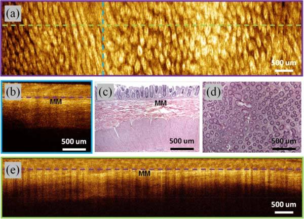
Ex vivo volumetric OCT images from human colon. (a) En face image at imaging depth of 350 μm. (b) Cross-sectional image along the fast-scan direction. (c) Representative cross-sectional histology of the human colon with hematoxylin and eosin stain. (d) Representative en face histology of the human colon with hematoxylin and eosin stain. (e) Cross-sectional image along the pullback direction. MM, muscularis mucosa.
Densely sampled volumetric 3D-OCT data sets contain comprehensive information about tissue microstructure and enable contrast enhancement of the images by averaging with the consecutive slices. Figure 9 shows an example by averaging a 15-μm-thick section, corresponding to seven consecutive slices This dimension corresponds to less than two epithelial cells, so tissue structure is largely constant and minimal blurring is observed. Figures 9 (a) and (b) show the images from the same ex vivo human colon data set with and without averaging respectively. The speckle pattern is decorrelated over the section and image averaging enhances tissue contrast. The arrow indicates a narrow line in the crypts, which is possibly the boundary of the lumen in the crypt. The averaging reduces speckle noise and thus reveals more detailed information from the tissue.
Fig. 9.
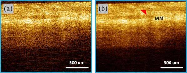
Image contrast enhancement by averaging. (a) Single slice. (b) Averaged image of a 15-μm-thick section. MM, muscularis mucosa.
4. Discussion
The PZT-bender-based imaging catheter enables high scanning speed and broad scanning range with low driving voltage. The distal scanning mechanism is less sensitive to bending of the catheter, and is therefore more stable than catheters that use proximal rotary actuation. The PZT catheter had the limitation that it provides only a limited transverse field of view compared with a rotary actuated catheter that scans a full 360 degree angle around the device. However, the PZT catheter is more stable and suitable for clinical endoscopy studies. The FDML laser with triple-buffered configuration has both very high sweep rate and broad wavelength tuning range, providing high axial line rate for in vivo imaging and good axial resolution that reveals important structural features in tissues. With the fast data acquisition, the imaging system can support good imaging depth range with ultrafast line rate. In this study, the PZT scanning frequency is 480 Hz and the laser line rate is 480 kHz, so each frame contains 500 lines over the scanning range of 2 mm, corresponding to an axial scan spacing of ~6.3 μm in the center and nearly zero on the edges. The pullback speed is 2 mm/s, corresponding a frame spacing of 2.1 μm. The data acquisition rate is 400 MS/s which can provide an imaging depth range of 2.3 mm in air.
With the high frame rate of the imaging system, the acquired data sets are less sensitive to the environmental motion, especially when performing in vivo endoscopic imaging. In upper endoscopy, the cardiac motion and breathing often induce motion artifacts in OCT images. The high frame rate can reduce the total data acquisition time, while maintaining data acquisition volume. The advantage of high imaging speed is that a densely sampled 3D volumetric data set that covers a broad area can be acquired in a short time with minimum motion artifacts. The volumetric data set can be viewed in a variety of orientations. Cross-sectional views provide depth and structural information in the tissue, while en face views can reveal the tissue structure over the field of view at a given depth. Moreover, with the densely sampled data sets, the image contrast can be further enhanced by averaging consecutive slices, so the speckle noise can be reduced.
The performance of the current prototype can be further improved. Although the GRIN lens performs well when the scanning laser beam is on axis, it causes severe aberration of the focused spot while the laser beam is off-axis. This is the main factor that limits the scanning range of the current prototype catheter. The off-axis aberrations can be reduced by using a compound lens design [21] with either a doublet or a triplet lens combination. The transverse resolution (the spot size on the focal plane) can also be improved by using a fiber with higher numerical aperture (NA) or changing the magnification of the optical design. A higher NA requires larger-diameter optics because the beam from the fiber diverges more rapidly. Changing magnification makes the spot size smaller at the cost of reduced scanning range. The PZT scanning in the transverse direction is highly repeatable, however there are potential discontinuities of motion when the optics are pulled back along the longitudinal direction. This can be a limiting factor in the image continuity when using a long catheter because of the friction between the catheter cable and the sheath along its length. Typical endoscopic applications in humans would require a 2 meter length. The effects of friction may be reduced by different choices of the catheter cable or sheath materials. Finally, the length of the PZT scanner, fiber and lens are 30 mm. This is too long to be introduced though the working channel of an endoscope. The working channel has a sharp radius bend at the proximal end of the endoscope, which requires a very short rigid length of the catheter, even for small outer diameter catheters. Therefore, the rigid length of the catheter needs to be reduced in future designs. Alternately, the catheter could be used with a daughter scope that consists of a tubing carried on the side of the standard endoscope.
In conclusion, we demonstrated an ultrahigh-speed endoscopic OCT imaging system with record frame rate using a PZT-bender-based imaging catheter, a triple-buffered FDML laser, and a high-speed data acquisition system. The system can support 960 frames per second with 480 kHz axial line rate, 11 μm axial resolution, 20 μm transverse resolution and 2.3 mm imaging depth range in air, corresponding to 8 μm axial resolution, 23 μm transverse resolution and 1.7 mm imaging depth range in tissue. High imaging speed was demonstrated in vivo in an animal model, enabling the visualization of microscopic features as small as colonic crypts. Three-dimensional endoscopic OCT data sets enable powerful visualization techniques including manipulation of tissue geometry, speckle reduction by averaging, generation of en face views similar to endoscopic images, and the generation of cross-sectional images with arbitrary orientations. Future improvements in the catheter design and data acquisition technology will allow volumetric imaging with enhanced microscopic resolution and at even higher frame rates and should enable a wide range of clinical 3D-OCT endomicroscopy applications.
Acknowledgments
We gratefully acknowledge Dr. Alison Hayward and Ms. Catrina Wong at MIT for assistance with the in vivo rabbit study, and Dr. Dejun Shen for the preparation of ex vivo human specimens. We also gratefully acknowledge technical assistance from Dr. Desmond Adler at LightLab Imaging / St Jude Medical. The research was sponsored in part by the National Institute of Health R01-CA75289-13, R01-EY011289-25 and R01-HL095717-02; the Air Force Office of Scientific Research FA9550-10-1-0063 and Medical Free Electron Laser Program FA9550-10-1-0551; German Research Foundation DFG-GSC80-SAOT. Tsung-Han Tsai acknowledges support from the Center for Integration of Medicine and Innovation Technology.
References and Links
- 1.Huang D., Swanson E. A., Lin C. P., Schuman J. S., Stinson W. G., Chang W., Hee M. R., Flotte T., Gregory K., Puliafito C. A., Fujimoto J. G., “Optical coherence tomography,” Science 254(5035), 1178–1181 (1991). 10.1126/science.1957169 [DOI] [PMC free article] [PubMed] [Google Scholar]
- 2.Tearney G. J., Boppart S. A., Bouma B. E., Brezinski M. E., Weissman N. J., Southern J. F., Fujimoto J. G., “Scanning single-mode fiber optic catheter-endoscope for optical coherence tomography,” Opt. Lett. 21(7), 543–545 (1996). 10.1364/OL.21.000543 [DOI] [PubMed] [Google Scholar]
- 3.Tearney G. J., Brezinski M. E., Bouma B. E., Boppart S. A., Pitris C., Southern J. F., Fujimoto J. G., “In vivo endoscopic optical biopsy with optical coherence tomography,” Science 276(5321), 2037–2039 (1997). 10.1126/science.276.5321.2037 [DOI] [PubMed] [Google Scholar]
- 4.Adler D. C., Chen Y., Huber R., Schmitt J., Connolly J., Fujimoto J. G., “Three-dimensional endomicroscopy using optical coherence tomography,” Nat. Photonics 1(12), 709–716 (2007). 10.1038/nphoton.2007.228 [DOI] [Google Scholar]
- 5.Suter M. J., Jillella P. A., Vakoc B. J., Halpern E. F., Mino-Kenudson M., Lauwers G. Y., Bouma B. E., Nishioka N. S., Tearney G. J., “Image-guided biopsy in the esophagus through comprehensive optical frequency domain imaging and laser marking: a study in living swine,” Gastrointest. Endosc. 71(2), 346–353 (2010). 10.1016/j.gie.2009.07.007 [DOI] [PMC free article] [PubMed] [Google Scholar]
- 6.Tearney G. J., Waxman S., Shishkov M., Vakoc B. J., Suter M. J., Freilich M. I., Desjardins A. E., Oh W.-Y., Bartlett L. A., Rosenberg M., Bouma B. E., “Three-dimensional coronary artery microscopy by intracoronary optical frequency domain imaging,” JACC Cardiovasc. Imaging 1(6), 752–761 (2008). 10.1016/j.jcmg.2008.06.007 [DOI] [PMC free article] [PubMed] [Google Scholar]
- 7.Sergeev A., Gelikonov V., Gelikonov G., Feldchtein F., Kuranov R., Gladkova N., Shakhova N., Snopova L., Shakhov A., Kuznetzova I., Denisenko A., Pochinko V., Chumakov Y., Streltzova O., “In vivo endoscopic OCT imaging of precancer and cancer states of human mucosa,” Opt. Express 1(13), 432–440 (1997). 10.1364/OE.1.000432 [DOI] [PubMed] [Google Scholar]
- 8.Aguirre A. D., Sawinski J., Huang S. W., Zhou C., Denk W., Fujimoto J. G., “High speed optical coherence microscopy with autofocus adjustment and a miniaturized endoscopic imaging probe,” Opt. Express 18(5), 4222–4239 (2010). 10.1364/OE.18.004222 [DOI] [PMC free article] [PubMed] [Google Scholar]
- 9.Liu X. M., Cobb M. J., Chen Y. C., Kimmey M. B., Li X. D., “Rapid-scanning forward-imaging miniature endoscope for real-time optical coherence tomography,” Opt. Lett. 29(15), 1763–1765 (2004). 10.1364/OL.29.001763 [DOI] [PubMed] [Google Scholar]
- 10.Jung W., McCormick D. T., Zhang J., Wang L., Tien N. C., Chen Z. P., “Three-dimensional endoscopic optical coherence tomography by use of a two-axis microelectromechanical scanning mirror,” Appl. Phys. Lett. 88(16), 163901 (2006). 10.1063/1.2195092 [DOI] [Google Scholar]
- 11.Kim K. H., Park B. H., Maguluri G. N., Lee T. W., Rogomentich F. J., Bancu M. G., Bouma B. E., de Boer J. F., Bernstein J. J., “Two-axis magnetically-driven MEMS scanning catheter for endoscopic high-speed optical coherence tomography,” Opt. Express 15(26), 18130–18140 (2007). 10.1364/OE.15.018130 [DOI] [PubMed] [Google Scholar]
- 12.Pan Y. T., Xie H. K., Fedder G. K., “Endoscopic optical coherence tomography based on a microelectromechanical mirror,” Opt. Lett. 26(24), 1966–1968 (2001). 10.1364/OL.26.001966 [DOI] [PubMed] [Google Scholar]
- 13.Sun J. J., Guo S. G., Wu L., Liu L., Choe S. W., Sorg B. S., Xie H. K., “3D in vivo optical coherence tomography based on a low-voltage, large-scan-range 2D MEMS mirror,” Opt. Express 18(12), 12065–12075 (2010). 10.1364/OE.18.012065 [DOI] [PubMed] [Google Scholar]
- 14.Wieser W., Biedermann B. R., Klein T., Eigenwillig C. M., Huber R., “Multi-megahertz OCT: High quality 3D imaging at 20 million A-scans and 4.5 GVoxels per second,” Opt. Express 18(14), 14685–14704 (2010). 10.1364/OE.18.014685 [DOI] [PubMed] [Google Scholar]
- 15.Huber R., Adler D. C., Fujimoto J. G., “Buffered Fourier domain mode locking: Unidirectional swept laser sources for optical coherence tomography imaging at 370,000 lines/s,” Opt. Lett. 31(20), 2975–2977 (2006). 10.1364/OL.31.002975 [DOI] [PubMed] [Google Scholar]
- 16.Potsaid B., Baumann B., Huang D., Barry S., Cable A. E., Schuman J. S., Duker J. S., Fujimoto J. G., “Ultrahigh speed 1050nm swept source/Fourier domain OCT retinal and anterior segment imaging at 100,000 to 400,000 axial scans per second,” Opt. Express 18(19), 20029–20048 (2010). 10.1364/OE.18.020029 [DOI] [PMC free article] [PubMed] [Google Scholar]
- 17.Biedermann B. R., Wieser W., Eigenwillig C. M., Klein T., Huber R., “Dispersion, coherence and noise of Fourier domain mode locked lasers,” Opt. Express 17(12), 9947–9961 (2009). 10.1364/OE.17.009947 [DOI] [PubMed] [Google Scholar]
- 18.L. E. Kinsler, A. R. Frey, A. B. Coppens, and J. V. Sanders, Fundamentals of Acoustics (Wiley, New York, 1982). [Google Scholar]
- 19.Huo L., Xi J., Wu Y., Li X., “Forward-viewing resonant fiber-optic scanning endoscope of appropriate scanning speed for 3D OCT imaging,” Opt. Express 18(14), 14375–14384 (2010). 10.1364/OE.18.014375 [DOI] [PMC free article] [PubMed] [Google Scholar]
- 20.International Electrotechnical Commission, “Medical electrical equipment—Part 1: General requirement for basic safety and essential performance,” IEC 60601–1 (2005).
- 21.Wu Y., Xi J., Cobb M. J., Li X., “Scanning fiber-optic nonlinear endomicroscopy with miniature aspherical compound lens and multimode fiber collector,” Opt. Lett. 34(7), 953–955 (2009). 10.1364/OL.34.000953 [DOI] [PMC free article] [PubMed] [Google Scholar]


