Abstract
This paper presents a numerical method for calculating the frequency response of a CMUT with a large number of cells. In a multi-cell configuration, commonly found in CMUTs, each cell is affected by the acoustic loading from neighboring cells. Thus, for an accurate model of a multi-cell CMUT element it is better to consider the mutual acoustic impedance instead of the acoustic impedance of a single cell only. We calculate the velocity of every cell (plate movement) simultaneously, with the mutual impedance effects taken into account. The model predicts that the cells exhibit different frequency responses, based on their locations in the element. We used a laser interferometer to validate the model by measuring the displacement response of a CMUT immersed in vegetable oil. The device has 169 circular cells (single crystal silicon plates, 500 nm thick, 21 μm radii) placed in a hexagonal cell arrangement. The measurement results agree well with the numerical results. The computation time of our method is significantly shorter than finite element based calculations. Our model can be used for finding optimized cell configurations for CMUTs utilized in various applications such as medical imaging and therapeutic treatment.
Keywords: CMUT, Acoustic impedance, Mutual impedance, MEMS
I. Introduction
Capacitive micromachined ultrasonic transducers (CMUTs) have been investigated for a wide range of applications, including medical imaging, therapeutics and sensor applications. In ultrasound applications, one of the key merits of CMUTs over piezo-based transducers is a larger bandwidth in immersion, even at higher operational frequencies. This wide bandwidth is the inherent result of the CMUT cell structure. The thin plate clamped at the post region has a low mechanical impedance, providing better acoustic matching to the medium, and, thus, a larger bandwidth.
However, due to the low mechanical impedance, the mutual impedance effects must be taken into account in the CMUT design process. The plate is not only actuated by electrostatic force, it is also affected by the pressure field generated by its neighboring cells. This effect has been empirically observed [1] and numerically analyzed [2, 3].
Our approach is to calculate the dynamics of every cell in an element considering the pressure field, generated by the neighboring cells in an arbitrary element configuration. First, we introduce the response of a single cell, which interacts with the surrounding medium. Second, additional acoustic influences from the neighboring cells (mutual impedance) are incorporated into the calculation. Third, the calculated results from the model are experimentally validated by measuring the frequency responses of a fabricated device.
II. Theory
A. Single-cell model
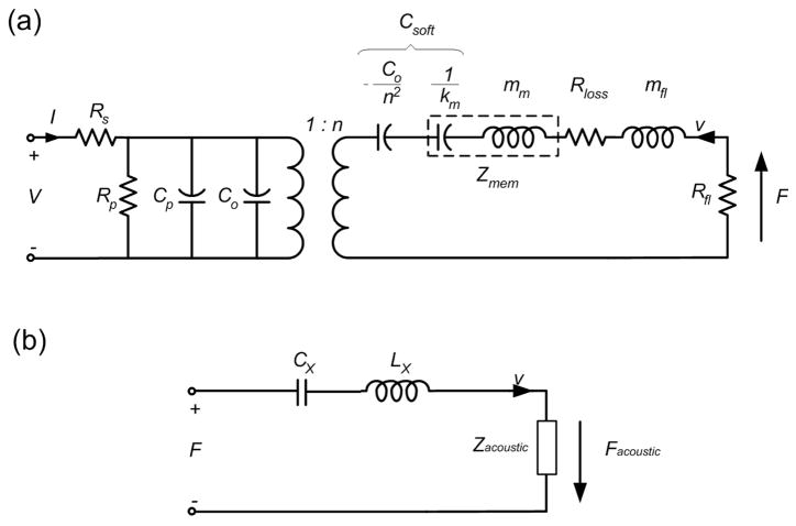
In order to simplify the analysis, we utilize the equivalent circuit model introduced by Mason [4]. Fig. 2(a) shows a typical equivalent circuit of a CMUT, including the electrical part (left side) and the mechanical part (right side). In this work, we consider the mechanical part of the equivalent circuit, which can be simplified into a three-component model [Fig. 2(b)]. In the simplified model, a voltage represents an applied force on a cell (plate) and a current represents an average velocity of the cell (plate). Both Cx and Lx represent the mechanical properties of the plate, which can be analytically calculated [5]. In the equivalent circuit model, Zacoustic is the acoustic impedance and can be defined as
Figure 2.
(a) Equivalent circuit of CMUT. All the components values are described in [5]. (b) Simplified equivalent circuit model.
| (1) |
where, Facoustic is the acoustic force applied by a pressure in the surrounding medium.
In the case of a CMUT with a single cell, this acoustic force is applied only by a pressure incurred by itself. Greenspan reported the acoustic impedance of this clamped radiator, Z11 as follows [6],
| (2) |
where r, A and c are the radius of the plate, the area of the plate, and the speed of sound in the medium, respectively. The solution of this equation, Z11 as a function of a normalized radius of the cell (kr) is shown in Fig. 3. When kr becomes significantly larger than 1, the generated wave can be estimated by a plane wave, and, thus, the real part of Z11 (R11) approaches to Z0. If kr becomes smaller than 1, however, the plate acts as a point source R11 becomes negligible compared to the imaginary part (X11).
Figure 3.
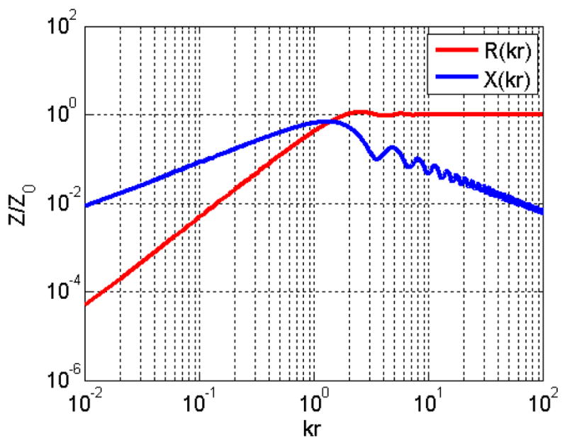
Real (R) and imaginary (X) part of acoustic impedance of single CMUT cell.
From (1) and (2), the average velocity, υ can be calculated as follows,
| (3) |
Since all the impedance parameters, ZC, ZL and Z11 are frequency dependent, a frequency response of a single cell should be extracted from υ at each frequency.
B. Multi-cell model
Typical CMUTs consist of multiple cells, closely packed, and, thus, require a model that considers this multi-cell configuration accurately. The acoustic impedance is affected by the neighboring cells. Consider two cells separated by a center-to-center distance of d. Then, the acoustic impedance of cell number 1 can be defined as follows,
| (4) |
where Z12 is a mutual acoustic impedance term due to the neighboring cell.
For a given mode shape of the cell (plate), the real part (R12) and the imaginary part (X12) of the mutual impedance are [7]
| (5) |
| (6) |
| (7) |
where α, Dτκ and Dsl are well described in [7]. If d is zero, the mutual impedance, Z12 is identical to Z11 in (2).
This approach can be extended for a larger number of cells than two. For a CMUT with n cells, the total acoustic impedance and the acoustic force of ith cell are
| (8) |
| (9) |
Accordingly, the velocity of ith cell, can be calculated as
| (10) |
Equation (10) assumes the velocity of other cells is known, and, thus, cannot be solved independently. Therefore, the velocity of all the cells must be simultaneously calculated for each frequency as
| (11) |
The dimension of the matrix in (11) is large for CMUTs with many cells. However, the dimension can be reduced for simpler calculations. First, ZC and ZL are identical for all the cells, as expressed in (11). Second, since the mutual impedance Zij is only dependent on kr and kd, many elements of Zij have the same value, e.g. if the distance between cell 1 and 2 and the distance between 3 and 4 are identical, Z12=Z21=Z34=Z41. Third, cells in a symmetric position have the same velocity (symmetry). For example, a seven-cell CMUT in a hexagonal distribution (blue color in Fig. 4) has six edge cells, which have the same symmetric position with respect to the center. Therefore, (11) can be further simplified into two expressions.
Figure 4.
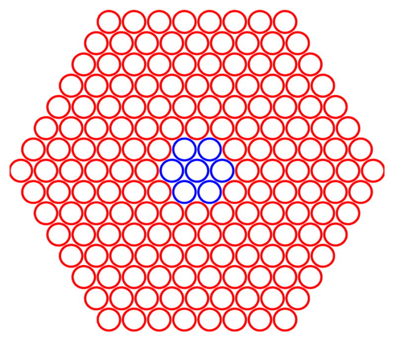
Diagram of cell locations in a hexagonal CMUT element. Blue circles represent a 7-cell CMUT, and blue and red circles together represent the 169-cell CMUT.
III. Results
A. Calculation
In this work, we calculated the velocity responses of CMUTs, which have 1, 7 and 169 cells in an hexagonal cell arrangement (Fig. 4). In this calculation, all cells are identical in terms of their material properties and dimensions, as it is the case the fabricated device (Fig. 5). Each cell consists of a single crystal silicon plate with a radius of 21 μm and a thickness of 500 nm. The cell-to-cell pitch is 45 μm.
Figure 5.
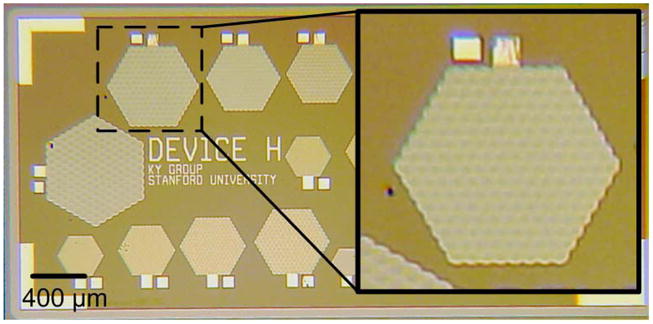
Optical picture of CMUT. The element in the zoomed picture is measrured in this work. It has 169 cells in a hexagonal element configuration.
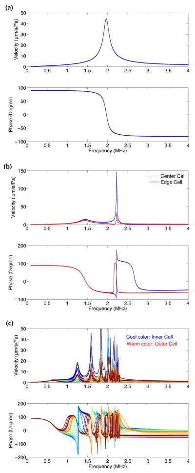
The velocity of each cell is calculated by (11) and the frequency responses are plotted in Fig. 6. There are three interesting characteristics to note. First, the frequency at which all cells have the same phase (first-mode frequency) decreases for an element with a larger number of cells. This first-mode frequency is 2 MHz, 1.4 MHz and 0.7 MHz for 1-cell, 7-cell and 196-cell CMUT, respectively. Second, for a multi-cell CMUT, different mode shapes of the elements are observed. At 2.2 MHz for the 7-cell CMUT and at 1.2 MHz for the 169-cell CMUT, the velocities of inner cells and outer cells have an opposite phase (second mode). For the 169-cell CMUT, other higher modes are present at higher frequencies. Third, when the frequency is larger than 2.5 MHz for the 169-cells, the entire higher modes disappear and only the edge cells [red color in Fig. 6(c)] have different responses. In this frequency range, the edge cells have about 40° phase delay compared to the other cells.
Figure 6.
Frequency responses of aveage velocity of (a) 1-cell (b) 7-cell (c) 169-cell CMUT. In (c), the line color represents the location of the cell from the center of the element. The cells near the center are represented in blue color and the edge cells are in red color.
B. Measurement of multi-cell CMUT
To validate the calculations from the previous section, the displacement of the fabricated CMUT, with 169 circular cells, was measured. The material properties and the dimensions of this device are identical to the specifications in the previous section.
The device is immersed in vegetable oil and excited with a fixed frequency. In this measurement, we select three excitation frequencies; the first-mode frequency, the second-mode frequency and a frequency of 4 MHz. During the excitation, the displacement of the surface of the device is measured by a laser interferometer.
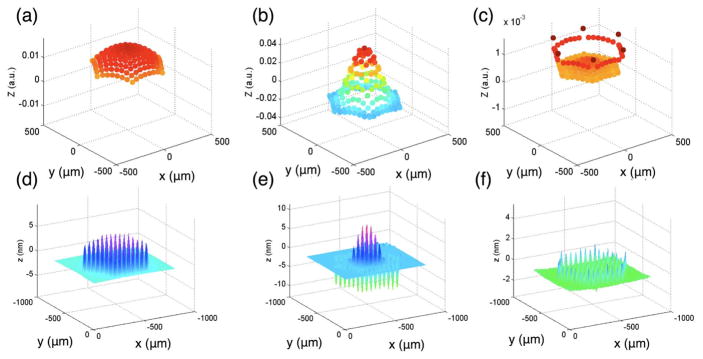
Fig. 7 shows both the calculated displacement [Fig. 7(a), (b), and (c)] and the measured displacements [Fig. 7(d), (e), and (f)] of 169 CMUT cells at different frequencies. The calculated results agree with the measurement data in terms of the first-mode and the-second mode frequencies. Moreover, the mode shape of the element at each frequency from calculation matches with that from the measurement.
Figure 7.
Calculated displacement pattern of 169 cells in the CMUT at (a) 0.67 MHz, (b) 1.3 MHz and (c) 4 MHz. Measurement of the displacement of the fabricated CMUT in immersion with an excitation frequency of (d) 0.7 MHz, (e) 1.26 MHz and (f) 4 MHz. The calculation results match well with the displacement measurement.
IV. Conclustion and Future Work
In this work, we calculated the velocity response of the multi-cell CMUT. Due to the low mechanical impedance of the cell, the multi-cell CMUT immersed in a liquid medium is highly affected by mutual acoustic impedance. Our model is verified by the displacement measurements of the fabricated 169-cell CMUT. Compared to the finite element method, the presented computation can be done significantly faster. Thus, using this method, design optimization and studies of various CMUT cell configurations can be conducted in a short period of time. As an extension of this work, the model should incorporate two additional parts in the future. First, the electrical part should be included in the model. Second, we need to investigate the pressure response of the multi-cell CMUT to provide a design guideline to maximize output pressure of a multi-cell CMUT.
Figure 1.
Schematic of cross section of a CMUT cell [8].
Acknowledgments
This work is supported by DARPA, Microsystems Technology Office under grant N66001-06-1-2030 and NIH grant 5R01CA134720.
This work was performed in part at the Stanford Nanofabrication Facility (a member of the National Nanotechnology Infrastructure Network), which is supported by the National Science Foundation under Grant ECS-9731293.
Contributor Information
K. K. Park, Edward L. Ginzton Laboratory, Stanford University, CA, U.S.A
M. Kupnik, Edward L. Ginzton Laboratory, Stanford University, CA, U.S.A
H. J. Lee, Edward L. Ginzton Laboratory, Stanford University, CA, U.S.A
B. T. Khuri-Yakub, Email: kwankyup@stanford.edu, Edward L. Ginzton Laboratory, Stanford University, CA, U.S.A
I. O. Wygant, NS Laboratories, National Semiconductor, CA, U.S.A
References
- 1.Bayram B, Kupnik M, Yaralioglu GG, Oralkan Ö, Ergun AS, Lin D, Wong SH, Khuri-Yakub BT. Finite element modeling and experimental characterization of crosstalk in 1-D CMUT arrays. Ultrason, Ferroelectr and Freq Control, IEEE Trans. 2007;54:418–430. doi: 10.1109/tuffc.2007.256. [DOI] [PubMed] [Google Scholar]
- 2.Ballandras S, Wilm M, Daniau W, Reinhardt A, Laude V, Armati R. Periodic finite element/boundary element modeling of capacitive micromachined ultrasonic transducers. J Appl Phys. 2005;97:034901. [Google Scholar]
- 3.Senlik MN, Olcum S, Koymen H, Atalar A. Radiation impedance of an array of circular capacitive micromachined ultrasonic transducers. Ultrason, Ferroelectr and Freq Control, IEEE Trans. 2010;57:969–976. doi: 10.1109/TUFFC.2010.1501. [DOI] [PubMed] [Google Scholar]
- 4.Mason WP. Electromechanical transducers and wave filters. Van Nostrand; London: 1948. [Google Scholar]
- 5.Ergun AS, Yaralioglu GG, Khuri-Yakub BT. Capacitive mi cromachined ultrasonic transducers: Theory and technology. J Aerospace Engineering. 2003;16:76–84. [Google Scholar]
- 6.Greenspan M. Piston radiator: Some extensions of the theory. J Acoust Soc Am. 1979;65:608–621. [Google Scholar]
- 7.Porter DT. Self- and Mutual-Radiation Impedance and Beam Patterns for Flexural Disks in a Rigid Plane. J Acoust Soc Am. 1964;36:1154–1161. [Google Scholar]
- 8.Park KK, Lee HJ, Kupnik M, Oralkan Ö, Khuri-Yakub BT. Fabricating capacitive micromachined ultrasonic transducers with direct wafer-bonding and LOCOS technology. Proc. 21th IEEE MEMS Conference; Tucson, USA. 2008. pp. 339–342. [Google Scholar]


