

Abstract
We report here on the formation of a bioactive hierarchically structured membrane by self-assembly. The membrane is formed with hyaluronic acid and peptide amphiphiles with binding affinity for heparin, and its hierarchical structure contains both an amorphous zone and a layer of fibrils oriented perpendicular to the membrane plane. The design of bioactivity is based on the potential ability to bind and slowly release heparin-binding growth factors. Human mesenchymal stem cells seeded on these membranes attached and remained viable. Basic fibroblast growth factor (FGF2) and vascular endothelial growth factor (VEGF) were incorporated within the membrane structure prior to self-assembly and released into media over a prolonged period of time (14 days). Using the chicken chorioallantoic membrane (CAM) assay, we also found that these membranes induced a significant and rapid enhancement of angiogenesis relative to controls.
1. Introduction
The field of biomaterials has been advancing toward molecular and nanoscale design of bioactivity for regenerative medicine and drug delivery [1, 2]. The use of peptides, proteins, and polysaccharides to design such materials provides a strategy to signal cells directly for biological outcomes and the potential for biodegradation once the biomaterial has served its function(s) [3, 4]. Our laboratory has demonstrated several examples of nanoscale design of bioactive peptide biomaterials, including systems for repair of spinal cord injury [5, 6], angiogenesis [7-9], cartilage [10] and bone regeneration [11-13], among others. These materials utilize an extensive family of peptide amphiphiles (PAs) developed in our laboratory that self-assemble into cylindrical nanofibers that mimic fibrillar components of extracellular matrices [14, 15]. These PAs contain a charged amino acid sequence covalently bound to an alkyl segment and create cylindrical assemblies of high aspect ratio through the formation of (β-sheets by part of the peptide and hydrophobic collapse of alkyl chains [16, 17]. Contact with aqueous medium of high ionic strength screens electrostatic repulsions amongst the charged molecules, leading to fiber entanglement and self-supporting gel networks.
The next challenge in molecularly designed bioactive biomaterials is to create more complex structures containing multiple components that are hierarchically organized, as seen in biological systems. We recently reported on a millisecond time scale process of self-assembly that forms a membrane at the interface between two aqueous solutions, one of high molecular weight hyaluronic acid (HA) and the other of a positively charged PA [18, 19]. This membrane has three zones: an amorphous layer; a region of nanofibers parallel to the contact interface, which form instantaneously; and a third zone of nanofibers aligned perpendicular to the interface that grows over longer time scales of minutes or longer. These hierarchically structured membranes require contact between oppositely charged components, and the solutions must have zeta potentials within a specific range [18].
HA, the biopolymer used in the first example reported of these hierarchical membranes, is a linear, negatively charged macromolecule containing a disaccharide repeat unit of N-acetylglucosamine and glucuronic acid that is present in mammalian extracellular matrices [20]. This biopolymer has been shown to affect cell migration, adhesion, and proliferation and play a crucial role in tissue organization, angiogenesis, and wound healing [4, 20]. Furthermore, its unique physicochemical properties, such as its strong affinity for water, make it an ideal biomaterial for a wide range of medical applications [3, 21, 22]. The peptide sequence VVVAAAKKK of the PA used previously is positively charged and did not contain a known biological signal. However, the PA that forms the membrane can in principle be customized to display specific biological signals on the surface of nanofibers as we have demonstrated in previous work [5, 7, 11, 23]. This offers a strategy to create bioactive HA/PA membranes.
In this work we have created a self-assembled bioactive hierarchical membrane functionalized with a heparin-binding PA (HBPA). HBPA contains a Cardin-Weintraub consensus heparin binding sequence to bind and display heparin loops on the surface of nanofibers in order to localize and activate potent angiogenic growth factors through their respective heparin-binding domains [7, 24]. The interactions between heparin, a highly sulfated glycosaminoglycan, and angiogenic growth factors such as vascular endothelial growth factor (VEGF) and basic fibroblast growth factor (FGF2) are known to play a major role in the signaling events during the formation of new blood vessels. Heparin acts as a cofactor in angiogenesis by binding growth factors, stabilizing receptors, and protecting these factors from proteolysis [7, 25, 26]. The delivery and display of VEGF and FGF2 by the HBPA-heparin nanofibers was previously found in our laboratory to enhance angiogenesis in vitro [24] and in vivo [7-9]. HBPA nanofiber gels have also been shown to persist in tissue for up to 30 days and exhibit excellent biocompatibility in vivo [26]. A mechanically robust and bioactive self-assembled membrane that could form in situ to cover arbitrary areas of tissue and deliver proteins could be a very useful construct in regenerative medicine. Bioactive membranes could be used to promote highly localized regeneration or to support healing at interfaces between two different tissues. In particular an angiogenic membrane would be beneficial in critical wound healing or cell transplantation. This work investigates the formation of such angiogenic membranes by studying their mechanical properties, interactions with cells and delivery of growth factors in vitro, and ability to promote angiogenesis in vivo.
2 Materials and methods
2.1 HBPA synthesis and purification
The heparin-binding peptide amphiphile (HBPA) was synthesized using standard fluoren-9-ylmethoxycarbonyl (Fmoc) solid phase peptide synthesis as previously reported [7] and purified using reversed phase high performance liquid chromatography (HPLC) in a methanol/water gradient under acidic conditions. After lyophilization, the purified material was solubilized in 50% acetonitrile in water with 0.1 % trifluoroacetic acetate (TFA) overnight. To improve biocompatibility of the purified HBPA, residual TFA counter ions were exchanged by sublimation from 0.01M HCl, resulting in the chloride salt of the product. After lyophilization from the HCl solution, HBPA was resolubilized in deionized water and lyophilized again and stored at -20°C until needed.
2.2 Membrane formation
The hyaluronic acid (HA; Lifecore Biomedical, Inc) used in all experiments had an average molar mass of 1.76 MDa. Porcine-derived heparin sodium salt was purchased from Sigma, and heparin labeled with fluorescein isothiocyanate (FITC-heparin) from Polysciences, Inc.
Four different HA/heparin biopolymer formulations, all containing 1 wt% HA, were prepared with variable heparin content of 0 wt%, 0.1 wt%, 0.25 wt%, and 0.5 wt% by mixing HA and heparin as powders prior to solubilizing in nanopure water, unless otherwise noted. Biopolymer solutions were prepared at least 24 hours before use. For all samples, lyophilized HBPA was solubilized in nanopure water at 2 wt% immediately prior to use.
Membranes were formed by the addition of the HBPA solution on top of the biopolymer solution, unless otherwise noted, and incubated in a humid, enclosed environment to avoid dehydration. After 4 hours of incubation, the membranes were rinsed carefully with nanopure water to remove excess biopolymer and HBPA.
2.3 Confocal microscopy
Confocal microscopy was used to probe the location of FITC-heparin (Polysciences, Inc) within the membrane cross-section. HA solutions (1 wt%) with 0 wt%, 0.1 wt%, 0.25 wt%, or 0.5 wt% FITC-heparin were prepared as described for HA/heparin solutions in section 2.2. Membranes were formed on circular polystyrene washers (inner diameter =10 mm). The washers were filled with 250 μL of the biopolymer solution and then 150 μL of HBPA solution was added on top and spread with a glass slide to form a continuous layer over the viscous biopolymer solution. The membranes were incubated at 4°C and protected from light to preserve fluorescence. After washing, membranes were transferred to glass microscopy slides, covered with a glass coverslip, and sealed to prevent dehydration.
Membranes were imaged with a Zeiss LSM 510 META laser scanning confocal microscope (LSCM) with the appropriate excitation and emission wavelengths for FITC (Ex = 488 nm, Em = 505-530 nm). Optical slices were captured at regular intervals to produce reconstructed z-stacks with 100 μm total thickness. Images of cross-sections were compiled from the z-stack in the x-direction using NIH ImageJ software.
2.4 SEM of membrane cross-section
To prepare samples for scanning electron microscopy (SEM), membranes were formed as closed sac membranes using a procedure described previously [18, 19]. The biopolymer and PA concentrations used to produce these sac membranes were consistent with those described in section 2.2. Briefly, sac membranes were formed by adding 20 μL of the biopolymer solution to 80 μL of the HBPA solution. An additional 40 uL of HBPA was added on top to fully immerse the biopolymer droplet and seal the sac membrane. The samples were allowed to incubate at room temperature before washing with water to remove excess HBPA. Samples were fixed in an aqueous solution containing 4% glutaraldehyde and 3% sucrose for 1 hour at 4°C and then subsequently dehydrated in an ethanol gradient from 20% to 100% ethanol in water. Critical point drying was performed with a Tousimis SAMDRI-795 critical point dryer. Dry samples were manually torn to expose the cross section then coated with 15 nm of osmium using an osmium plasma coater (Structure Probe, Inc.). Samples were imaged using a Hitachi S-4800 field emission scanning electron microscopy using an accelerating voltage of 3 kV.
2.5 Membrane inflation
Membranes (N = 4 per group) for membrane inflation were formed in circular polystyrene washers (inner diameter = 20 mm) by filling with 950μL of the biopolymer solution and adding 500 μL of HBPA on top of the biopolymer solution. The HBPA solution was spread with a glass slide to form a continuous layer to ensure a complete membrane across the washer. Membranes were incubated at room temperature for 4 hours then rinsed carefully with nanopure water to remove excess biopolymer and HBPA.
Inflation of the membrane was completed as described previously [19]. The membrane was carefully transferred from the washer to a metal holder and secured with a ring clamp. A few drops of water were added on top of the membrane to ensure hydration. The sample in the holder was placed on a custom-built apparatus for membrane inflation. Inflation was controlled with a syringe pump (New Era Pump Systems), and images were recorded with a color camera (JAI) to monitor deformation while pressure was measured using a pressure sensor (MKS Instruments). The area modulus, given by Eh where h is the membrane thickness and E is the average Young's modulus through the thickness, was determined using a neo-Hookean model described previously [19]. Data points are shown as mean area modulus with error bars equal to the standard deviation.
2.6 Cell viability
Membranes were formed on polystyrene washers (inner diameter = 13 mm) as described above. After washing, membranes were treated with 10% human serum (Sigma) in PBS (Hyclone) overnight in the incubator at 37°C at 5% CO2. Samples were washed three times with PBS then incubated with mesenchymal stem cell (MSC) media (Lonza) overnight. The next day, membranes were washed 3 times with DPBS then seeded with bone marrow derived human MSCs from spina bifida patients at a density of 5,000 cells per cm2. Media was changed every other day until staining for viability on day 5. Viability was assessed using a Live/Dead™ Viability/Cytotoxicity Kit (Invitrogen) that uses calcein to stain live cells green and ethidium homodimer-1 to stain dead cells red. Cells on membranes were imaged using a Nikon inverted fluorescent microscope with the appropriate filters. Bone marrow samples were obtained in accordance with regulations set forth by the Institutional Review Board of Children's Memorial Hospital in Chicago, Illinois, USA.
2.7 Growth factor release from membranes
Human recombinant FGF2 or VEGF165 (both from Peprotech, Inc.) was included during membrane formation to compare the effect of heparin concentration on the release of heparin-binding growth factors. Both of these growth factors are known to have heparin-binding domains along with potent angiogenic activity [27-29]. Heparin solutions at 0 wt%, 0.1 wt%, 0.25 wt% and 0.5 wt% were prepared by dissolving heparin in water. FGF2 or VEGF was added to the water or heparin solution prior to solubilizing HA for a final concentration of 250 ng per membrane. The biopolymer solutions were stored at 4°C overnight prior to use.
Membranes (N=4 per group) were formed in 48-well plates by adding 150 μL of the HBPA solution on top of 150 μL of the biopolymer solution and incubated at 4°C for 4 hours. After thorough washe s with nanopure water, all liquid was completely removed from the wells before adding 500 μL release media composed of phosphate buffered saline (PBS; Hyclone) supplemented with 1% bovine serum albumin (BSA; SeraCare Life Sciences), 10mM ethylenediaminetetraacetic acid (EDTA; Sigma), and 10ug/mL heparin sodium salt (Sigma). Membranes were stored in an incubator at 37°C with 5% CO2 for the duration of study. Samples were collected daily from days 1 to 7 then on days 9, 11, and 14 by removing all of release media and replacing with 500 μL of release media and storing the collected sample at -80°C.
Samples were thawed at room temperature then centrifuged to remove any debris or precipitate. The concentration of GF in each sample was measured using commercially available enzyme-linked immunosorbent assay kit (ELISA; R&D Systems) for human recombinant FGF2 or VEGF. Samples were processed according to assay instructions. For endpoint analysis, absorbance measurements were collected on a Spectramax M5 plate reader at 450 nm and the background at 540 nm was subtracted. Data is shown as the mean cumulative percent of GF released over time with error bars representing standard error of the mean.
2.8 Chorioallantoic membrane (CAM) angiogenesis assay
In order to evaluate the angiogenic response resulting from presentation and release of bound growth factors, we employed the well-established method for in vivo angiogenesis known as the chicken chorioallantoic membrane (CAM) assay. This assay utilizes the extraembryonic allantois, a tissue derived from the mesoderm that develops into a densely vascularized membrane. A common deviation from the traditional assay is to remove the shell, termed the shell-less CAM assay, as we have performed here [30, 31]. Fertilized white leghorn chicken eggs (Phil's Fresh Eggs, Forreston, IL) were received and cultured in a temperature controlled, humidified egg incubator. On embryonic day 3, eggs were cracked within a laminar flow hood into round 100 mm petri dishes. Fertilized embryos were then transferred to a water-jacketed CO2 incubator set to 37.5° C, 1 % CO2 and 100% relative humidity.
One day prior to application on the CAM, membranes were formed in circular polyurethane washers (inner diameter = 5 mm) by filling with 40 μL of the biopolymer solution and adding 15 μL of HBPA on top. After 4 hours, membranes were washed with water then incubated overnight in the release buffer used in section 2.6. Membranes (N ranging 20 to 31 per group) were placed onto the CAM on embryonic day 10. Digital images were captured through the eyepiece of a Nikon stereomicroscope immediately after applying the membrane and again on embryonic day 11. The vessel density was quantified by the number of intersections of vessel structures with the borders of the membrane and expressed relative to that number at the time of initial application.
2.8 Statistics and data analysis
Error bars for growth factor release and vessel density indicate the standard error of the mean. Differences between groups were determined using a one-way analysis of variance (ANOVA) with a Bonferroni multiple comparisons post-hoc test using GraphPad InStat v3.0b.
3. Results and Discussion
Previous work in our laboratory demonstrated that heparin bound to HBPA nanofibers can bind and localize growth factors through heparin-binding domains of these proteins, resulting in enhanced growth factor bioactivity [7, 8, 24]. In this study, we incorporated varying concentrations of heparin into HA/HBPA membranes during membrane formation to modulate the release of growth factors from these membranes. Solid planar HA/HBPA membranes were formed instantaneously with heparin at concentrations ranging from 0 wt% to 0.5 wt%. To confirm heparin was integrated into the membranes, we used FITC-conjugated heparin and imaged the membranes using confocal laser scanning microscopy. Confocal microscopy confirmed that FITC-heparin is present in the 0.1 wt%, 0.25 wt%, and 0.5 wt% heparin membranes (Fig. 1). As expected, no fluorescence was detected in the 0 wt% FITC-heparin membrane control. Interestingly, the macroscopic properties of the membranes were notably affected due to the presence of heparin. Membranes containing heparin were more wrinkled compared to HA/HBPA membranes without heparin. In Figures 1c-d, fluorescence from FITC-heparin appeared to be discontinuous throughout the membrane and correlated with wrinkles in the membrane seen in the phase images. The membrane cross-sections (Figs. 1f-h), however, demonstrated that FITC-heparin is present homogeneously throughout the thickness of the membrane, suggesting the discontinuous appearance in the single slice is a feature linked to membrane wrinkling rather than inhomogeneity of heparin within the membrane.
Figure 1.
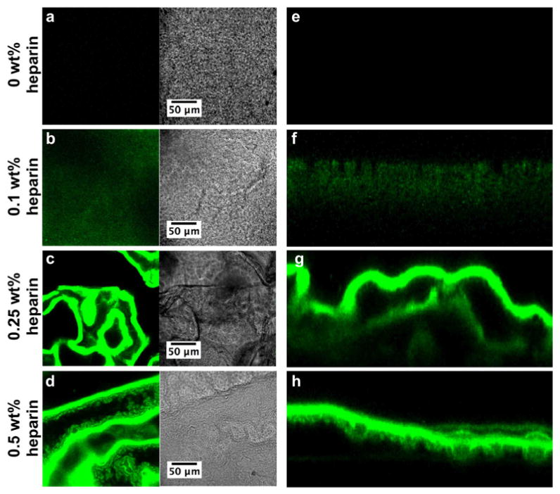
Confocal laser scanning microscopy images of membranes self-assembled from 2 wt% HBPA and 1 wt% HA with (a, e) 0 wt%, (b, f) 0.1 wt%, (c, g) 0.25 wt%, and (d, h) 0.5 wt% FITC-heparin (green). (a-d) show a representative 1 μm-thick optical slice of each membrane in fluorescence and phase modes. (e-h) are cross-sections of the membrane compiled from the z-stack.
Scanning electron microscopy (SEM) showed that heparin affects the microstructure of the membranes dramatically (Fig. 2). Surprisingly, the 0 wt% heparin membrane (Fig. 2a) appeared disordered and did not have the three distinct zones seen previously for HA and the VVVAAAKKK PA [18, 19]. With increasing heparin concentration, the perpendicular nanofibers previously observed become more predominant in the membrane structure, indicating some interaction between HBPA and heparin may be essential to the formation of the hierarchical structure discovered earlier. The membranes with 0.1 wt% and 0.25 wt% heparin contained large bundles of fibers perpendicular to the interface. When heparin content was increased to 0.5 wt%, the structure of the membranes resembled that observed in the original HA/PA membranes [18, 19], suggesting a possible critical heparin concentration between 0.25 wt% and 0.5 wt% is necessary for the distinct structural regions to develop during self-assembly.
Figure 2.
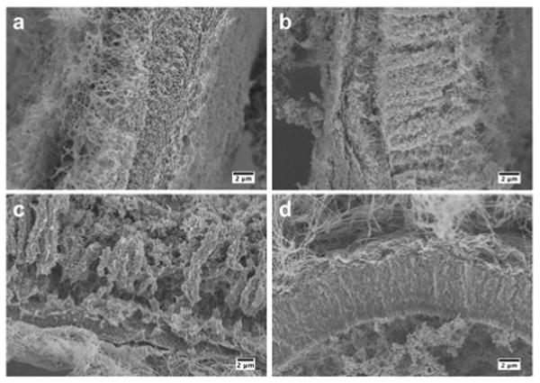
Scanning electron micrographs of membranes self-assembled from 2 wt% HBPA and 1 wt% HA with (a) 0 wt%, (b) 0.1 wt%, (c) 0.25 wt%, and (d) 0.5 wt% heparin incubated for 4 hours. Images show representative cross-sections of the membranes.
Structural features and mechanical properties have been shown to be directly related in HA/PA membranes [19]. To determine if the structural differences observed here with heparin content translate into differences in mechanical properties, the area moduli of membranes were determined based on membrane inflation measurements (Fig. 3). Increasing heparin content was found to correlate to a decrease in the area modulus Eh. However, the area modulus is dependent on the thickness of the hydrated membrane, and we observed macroscopically that increasing heparin concentrations decreased the thickness of the membrane. Measuring the thickness of a hydrated membrane is challenging with traditional methods and could not be performed here. Profilometry (data not shown) was used to obtain approximate thicknesses of dried membranes. We found a thickness of 30 μm for 0 wt% heparin and 5 μm for 0.5 wt% heparin, giving an estimated E of 0.35 MPa and 0.68 MPa, respectively. These results indicate that stiffer membranes are obtained when heparin is added to the biopolymer solution. Changing heparin concentration in the membrane provides an interesting method to adjust mechanical properties while incorporating a biological molecule.
Figure 3.
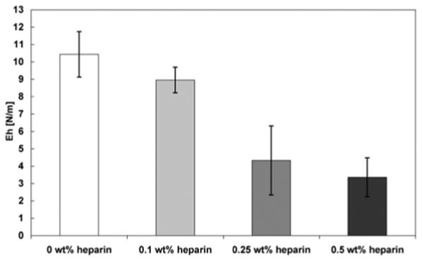
Area modulus Eh determined by membrane inflation of membranes self-assembled from 2 wt% HBPA and 1 wt% HA with varying concentrations of heparin after incubating for 4 hours. Increasing heparin concentration correlates to a decrease in area modulus.
Human mesenchymal stem cells (hMSCs) were seeded on the surface of the membranes to evaluate viability of cells in contact with them. The cells attached and spread on all membranes by day 5 (Fig. 4). Membrane wrinkling, as shown in Figure 1, made it difficult to image the cells in one plane so the cell density appears to decrease with increasing heparin content. Some red fluorescence used to indicate dead cells also labeled the membranes with higher heparin content non-specifically. Upon closer inspection, however, there was no significant difference in viability or cell density due to heparin content. Cells were found in different planes of the membrane, shown by cells in and out of focus, which may indicate migration of cells into the membrane. Interestingly, the morphologies of the cells on all membranes were different from those found on traditional 2D tissue culture-treated plastic and may represent MSC morphology in 3D. The MSCs on the membrane had an extended, fibroblast-like morphology as previously described [32]. These membranes could be seeded with cells on one or both sides, which may be useful for applications such as wound healing where different cell types are needed.
Figure 4.
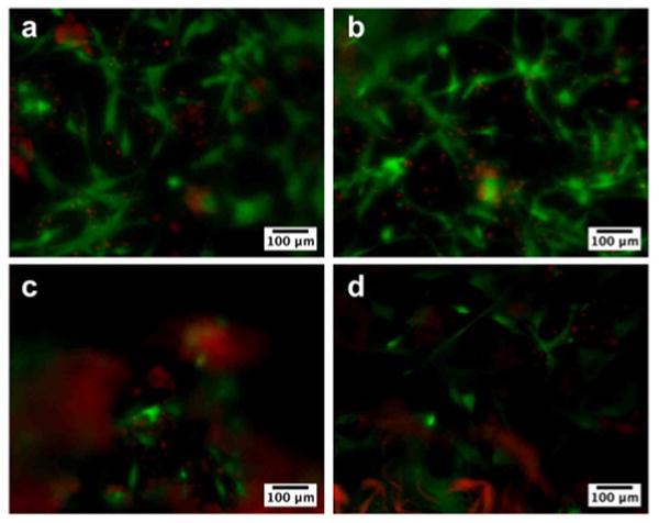
Fluorescence microscopy images showing viability of human mesenchymal stem cells (hMSCs) seeded on membranes formed from 2 wt% HBPA and 1 wt% HA with (a) 0 wt%, (b) 0.1 wt%, (c) 0.25 wt%, and (d) 0.5 wt% heparin at day 5. HMSCs were stained for live (green) and dead (red) cells and appeared to attach and grow on all membranes. The difference in cell density is not a reflection of an effect on proliferation but rather a result of uneven resolution because the membranes are not completely flat and become more wrinkled with increasing heparin concentration. Nonspecific red fluorescence was also seen in membranes containing higher amounts of heparin.
The presence of heparin within the membrane was expected to affect the release of FGF2 and VEGF since a previous study showed HBPA/heparin nanofiber gels extended FGF2 release relative to HBPA gels without heparin [7]. VEGF and FGF2 were incorporated into the membranes during their formation, and release of the growth factors was monitored during a period of 14 days. Increasing the concentration of heparin in the membrane directly resulted in both a decreased and prolonged release of both FGF2 and VEGF (Fig. 5). In the 0 wt% heparin membrane, all of the detectable FGF2 was released within 4 days (Fig. 5a). Membranes containing 0.1 wt% and 0.25 wt% heparin showed significantly lower FGF2 release in the first day of the study (P<0.05) compared to membranes without heparin. These membranes containing 0.1 wt% and 0.25 wt% heparin released all detectable FGF2 by day 9. Increasing the heparin content of the membrane to 0.5 wt% significantly slowed release compared to 0 wt% membranes at day 1 (P<0.01), though this group did not vary significantly from 0.1 wt% or 0.25 wt% heparin membranes. However, beginning at day 2 and extending through day 6, the 0.5 wt% heparin group had a significantly decreased release (P<0.05, P<0.01, P<0.01, P<0.001, P<0.01 for days 2-6, respectively) from all other groups and released a detectable amount of FGF2 during all 14 days of the study. Heparin has also been shown to prolong the release of VEGF and FGF2 from chemically modified crosslinked HA/heparin hydrogels [22]. In the supramolecular membranes studied here, the prolonged release of growth factors is observed without the need to crosslink polymers through chemical modifications. This could combine in the hierarchical membranes prolonged release of growth factors with enhanced biocompatibility and faster biodegradation.
Figure 5.
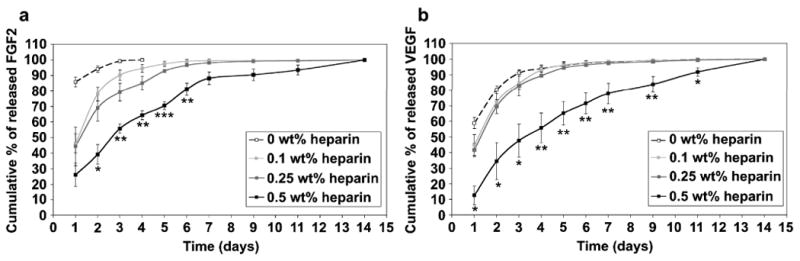
Cumulative release of (a) FGF-2 and (b) VEGF from membranes self assembled from 2 wt% HBPA and 1 wt% HA with varying concentrations of heparin. Statistical significance is only shown for 0.5 wt% heparin against all other groups (*P<0.05, **P<0.01, ***P<0.001).
VEGF release from the membranes (Fig. 5b) followed a similar trend as that for FGF2. Most of the detectable VEGF was released from the 0 wt%, 0.1 wt% and 0.25 wt% by day 7, and there was no significant difference between these three groups at any point in the study. VEGF release was slowed significantly (P<0.05 for days 1, 2, 3, and 11 and P<0.01 for days 4, 5, 6, 7, and 9) in the 0.5 wt% heparin membrane at time points from day 1 through day 11 relative to all of the other groups evaluated. As with FGF2, a detectable amount of VEGF was released from the 0.5 wt% heparin membranes at day 14, suggesting growth factor release continues beyond the time frame of the study.
Interestingly, the prolonged release from the 0.5 wt% heparin HA/HBPA membranes correlates to their distinct hierarchical features, in particular the zone of macroscopically oriented nanofibers (containing HBPA, HA, and heparin) with orientation perpendicular to the initial liquid-liquid area of contact. Diffusion of the growth factors through this region may be inhibited due to the high nanofiber density and potential affinity between the growth factors and heparin-displaying nanostructures. In addition to regulating the release, heparin may affect the initial amount of growth factor incorporated into the membrane. In these studies, growth factors were added to the biopolymer solution prior to membrane formation so that they could be present at the time of membrane formation. A greater amount of heparin could bind more growth factor, leading to differences in initial growth factor loading of the membrane depending on heparin content.
As the 0.5 wt% heparin membranes were the ones that altered growth factor release considerably, they were evaluated further to establish their angiogenic efficacy in vivo. The well-established CAM assay was used here to assess their angiogenic nature resulting from the presentation and release of bound growth factors within these membranes. For this in vivo study, we compared four different membranes with or without 0.5 wt% heparin and with or without added FGF2 and VEGF growth factors. Digital images of the membrane obtained while conducting the CAM assay experiments are shown in Figure 6. Within one day, no dramatic changes in peri-membrane vessel density or vessel morphology were observed qualitatively in the non-heparin containing membrane heparin without (Fig. 6b) or with (Fig. 6d) growth factors. Additionally, there were no major qualitative differences observed for membranes prepared with 0.5 wt% heparin without growth factors compared to the non-heparin containing membranes. However, the 0.5 wt% heparin membrane with VEGF and FGF2 induced a dramatic increase in vessel number, diameter, and morphology in the peri-membrane vasculature. The arrows in Figure 6h indicate “corkscrew” vessel morphologies that are a hallmark of VEGF signaling. VEGF is known to promote the proliferation and survival of endothelial cells [33]. This growth factor is also known to induce vessel sprouting [34] and capillary formation [35] while FGF2 also encourages endothelial cell proliferation and migration. FGF2 is also closely tied to the formation of mature vessels [36], the process by which existing vessels increase in size and diameter as shown (Fig. 6h). In addition, FGF2 and VEGF have been shown to work synergistically to enhance angiogenic activity [35]. The observations in these studies are consistent with the known activities of these two signaling proteins.
Figure 6.

Digital images of membranes self-assembled from 2 wt% HBPA and 1 wt% HA with (a, b) 0 wt% heparin, (c, d) 0 wt% heparin with VEGF and FGF2, (e, f) 0.5 wt% heparin, and (g, h) 0.5 wt% heparin with VEGF and FGF2 on the chorioallantoic membrane on days 0 and 1. Arrows in (h) indicate vessel morphology indicative of VEGF signaling.
The vessel density was quantified by measuring the number intersecting the edges of the membrane relative to day 0 (Fig. 7). All groups showed an increase in average vessel density after 1 day, though there was no statistical difference between membranes lacking heparin with (117% ± 3.1%) or without (112.2% ± 1.5%) growth factors. The 0.5 wt% heparin membrane with growth factors (151.2% ± 4.1%) resulted in a significant increase (P<0.001) in vessel density compared to all groups after only 1 day. Interestingly, the 0.5 wt% heparin membrane without growth factors did not have any dramatic effect on angiogenesis qualitatively but quantitative analysis reveals the vessel density for this membrane (129.1% ± 3.9%) is significantly greater (P<0.001) than that of membranes without heparin and growth factors. However, the vessel density is not significantly greater than that of membranes without heparin but containing growth factors. The observation that heparin-containing membranes without growth factors elicit an angiogenic response is not surprising given our previous work which demonstrated that HBPA-heparin gels can induce the formation of vascularized tissue in vivo without additional growth factors [26]. Additionally, HBPA-heparin gels were demonstrated to be effective at binding and delivering secreted factors from hypoxic-conditioned media and promoted myocardial salvage [37]. The CAM is a very pro-angiogenic tissue with a rich supply of endogenous factors. Our data presented here and previously indicate that 0.5 wt% heparin-containing HBPA/HA membranes may be recruiting and localizing the endogenous factors within the CAM to locally increase vessel density. It is also possible that some heparin may be released from the membrane over time, contributing to the bioactivity of the growth factors in a soluble role.
Figure 7.

Vessel density relative to day 0 induced by HA/HBPA membranes with 0 wt% or 0.5 wt% heparin with or without VEGF and FGF2 (***P<0.001).
The 0.5 wt% heparin membrane prolonged growth factor release in vitro (Fig. 5) and also enhanced angiogenesis in vivo (Fig. 6 and 7) compared to membranes that did not contain heparin. The addition of 0.5 wt% heparin also resulted in the formation of the perpendicular nanofiber morphology in the membrane (Fig. 2d). As stated above, a critical concentration of heparin between 0.25 and 0.5 wt% was found to be necessary to form this hierarchical membrane structure. It is possible that it is not just the incorporation of heparin that leads to its bioactivity, but also that the hierarchical microstructure of the membrane plays some role in growth factor binding, presentation, and release. Understanding the origin of heparin's effect on membrane microstructure, however, requires an extensive investigation that is beyond the scope of this paper but is currently being explored in our laboratory.
Hierarchically structured self-assembling membranes composed of HA, a heparin-binding PA, and heparin offer novel ways to control growth factor release and promote angiogenesis. These membranes could function as bioactive wound dressings for chronic non-healing wounds or cell transplantation, among other functions. Other growth factors such as bone morphogenetic protein-2 (BMP-2) important in stem cell differentiation and bone regeneration are known to bind heparin. Therefore, the membranes may find interesting applications in other areas of regenerative medicine. Furthermore, another attractive feature of these systems is the possibility of forming them at tissue sites by self-assembly into a variety of shapes and sizes.
4. Conclusions
We have developed a strategy to create bioactive self-assembled membranes formed by contact between two aqueous solutions. These membranes were found to have hierarchical structures that permit the facile and sustained delivery of growth factor proteins into cell media. Using an in vivo assay, the model system investigated here was shown to promote rapid angiogenesis utilizing heparin-binding growth factors involved in signaling for angiogenesis. The strategy investigated could be useful in many regenerative medicine applications and wound healing therapies.
Acknowledgments
This work was supported by the National Institute of Biomedical Imaging and Bioengineering at the National Institutes of Health (1R01EB003806) and the NSF MRSEC program (DMR-0520513). Additional support from the Ben Gurion University in Negev, Israel is also acknowledged in the form of a postdoctoral fellowship for R.B. Experiments made use of the following facilities at Northwestern University: EPIC Facilities of the NUANCE Center, Center for Comparative Medicine, the Cell Imaging Facility, and the Institute for BioNanotechnology in Medicine. The NUANCE Center is supported by the NSF-NSEC, NSF-MRSEC, Keck Foundation, the State of Illinois and Northwestern University. The authors thank Dr. James Hulvat and Dr. Liam Palmer for useful discussions and Dr. Josh Goldberger for profilometry measurements.
Footnotes
Publisher's Disclaimer: This is a PDF file of an unedited manuscript that has been accepted for publication. As a service to our customers we are providing this early version of the manuscript. The manuscript will undergo copyediting, typesetting, and review of the resulting proof before it is published in its final citable form. Please note that during the production process errors may be discovered which could affect the content, and all legal disclaimers that apply to the journal pertain.
References
- 1.Webber MJ, Kessler JA, Stupp SI. Emerging peptide nanomedicine to regenerate tissues and organs. J Intern Med. 2010;267(1):71–88. doi: 10.1111/j.1365-2796.2009.02184.x. [DOI] [PMC free article] [PubMed] [Google Scholar]
- 2.Langer R, Tirrell DA. Designing materials for biology and medicine. Nature. 2004;428(6982):487–492. doi: 10.1038/nature02388. [DOI] [PubMed] [Google Scholar]
- 3.Rinaudo M. Main properties and current applications of some polysaccharides as biomaterials. Polym Int. 2008;57(3):397–430. [Google Scholar]
- 4.Baldwin AD, Kiick KL. Polysaccharide-modified synthetic polymeric biomaterials. Peptide Science. 2010;94(1):128–140. doi: 10.1002/bip.21334. [DOI] [PMC free article] [PubMed] [Google Scholar]
- 5.Silva GA, Czeisler C, Niece KL, Beniash E, Harrington DA, Kessler JA, Stupp SI. Selective differentiation of neural progenitor cells by high-epitope density nanofibers. Science. 2004;303(5662):1352–1355. doi: 10.1126/science.1093783. [DOI] [PubMed] [Google Scholar]
- 6.Tysseling-Mattiace VM, Sahni V, Niece KL, Birch D, Czeisler C, Fehlings MG, Stupp SI, Kessler JA. Self-assembling nanofibers inhibit glial scar formation and promote axon elongation after spinal cord injury. J Neurosci. 2008;28(14):3814–3823. doi: 10.1523/JNEUROSCI.0143-08.2008. [DOI] [PMC free article] [PubMed] [Google Scholar]
- 7.Rajangam K, Behanna HA, Hui MJ, Han XQ, Hulvat JF, Lomasney JW, Stupp SI. Heparin binding nanostructures to promote growth of blood vessels. Nano Lett. 2006;6(9):2086–2090. doi: 10.1021/nl0613555. [DOI] [PubMed] [Google Scholar]
- 8.Chow LW, Wang LJ, Kaufman DB, Stupp SI. Self-assembling nanostructures to deliver angiogenic factors to pancreatic islets. Biomaterials. 2010;31(24):6154–6161. doi: 10.1016/j.biomaterials.2010.04.002. [DOI] [PMC free article] [PubMed] [Google Scholar]
- 9.Stendahl JC, Wang LJ, Chow LW, Kaufman DB, Stupp SI. Growth factor delivery from self-assembling nanofibers to facilitate islet transplantation. Transplantation. 2008;86(3):478–481. doi: 10.1097/TP.0b013e3181806d9d. [DOI] [PMC free article] [PubMed] [Google Scholar]
- 10.Shah RN, Shah NA, Lim MMD, Hsieh C, Nuber G, Stupp SI. Supramolecular design of self-assembling nanofibers for cartilage regeneration. Proc Natl Acad Sci U S A. 2010;107(8):3293–3298. doi: 10.1073/pnas.0906501107. [DOI] [PMC free article] [PubMed] [Google Scholar]
- 11.Mata A, Geng YB, Henrikson KJ, Aparicio C, Stock SR, Satcher RL, Stupp SI. Bone regeneration mediated by biomimetic mineralization of a nanofiber matrix. Biomaterials. 2010;31(23):6004–6012. doi: 10.1016/j.biomaterials.2010.04.013. [DOI] [PMC free article] [PubMed] [Google Scholar]
- 12.Sargeant TD, Guler MO, Oppenheimer SM, Mata A, Satcher RL, Dunand DC, et al. Hybrid bone implants: self-assembly of peptide amphiphile nanofibers within porous titanium. Biomaterials. 2008;29(2):161–171. doi: 10.1016/j.biomaterials.2007.09.012. [DOI] [PubMed] [Google Scholar]
- 13.Sargeant TD, Oppenheimer SM, Dunand DC, Stupp SI. Titanium foam-bioactive nanofiber hybrids for bone regeneration. J Tissue Eng Regen Med. 2008;2(8):455–462. doi: 10.1002/term.117. [DOI] [PMC free article] [PubMed] [Google Scholar]
- 14.Hartgerink JD, Beniash E, Stupp SI. Self-assembly and mineralization of peptide-amphiphile nanofibers. Science. 2001;294(5547):1684–1688. doi: 10.1126/science.1063187. [DOI] [PubMed] [Google Scholar]
- 15.Hartgerink JD, Beniash E, Stupp SI. Peptide-amphiphile nanofibers: A versatile scaffold for the preparation of self-assembling materials. Proc Natl Acad Sci U S A. 2002;99(8):5133–5138. doi: 10.1073/pnas.072699999. [DOI] [PMC free article] [PubMed] [Google Scholar]
- 16.Jiang HZ, Guler MO, Stupp SI. The internal structure of self-assembled peptide amphiphiles nanofibers. Soft Matter. 2007;3(4):454–462. doi: 10.1039/b614426h. [DOI] [PubMed] [Google Scholar]
- 17.Velichko YS, Stupp SI, de la Cruz MO. Molecular simulation study of peptide amphiphile self-assembly. J Phys Chem B. 2008;112(8):2326–2334. doi: 10.1021/jp074420n. [DOI] [PubMed] [Google Scholar]
- 18.Capito RM, Azevedo HS, Velichko YS, Mata A, Stupp SI. Self-assembly of large and small molecules into hierarchically ordered sacs and membranes. Science. 2008;319(5871):1812–1816. doi: 10.1126/science.1154586. [DOI] [PubMed] [Google Scholar]
- 19.Carvajal D, Bitton R, Mantei JR, Velichko YS, Stupp SI, Shull KR. Physical properties of hierarchically ordered self-assembled planar and spherical membranes. Soft Matter. 2010;6(8):1816–1823. [Google Scholar]
- 20.Allison DD, Grande-Allen KJ. Review: Hyaluronan: a powerful tissue engineering tool. Tissue Eng. 2006;12(8):2131–2140. doi: 10.1089/ten.2006.12.2131. [DOI] [PubMed] [Google Scholar]
- 21.Price RD, Myers S, Leigh IM, Navsaria HA. The role of hyaluronic acid in wound healing - assessment of clinical evidence. Am J Clin Dermatol. 2005;6(6):393–402. doi: 10.2165/00128071-200506060-00006. [DOI] [PubMed] [Google Scholar]
- 22.Pike DB, Cai SS, Pomraning KR, Firpo MA, Fisher RJ, Shu XZ, Prestwich GD, Peattie RA. Heparin-regulated release of growth factors in vitro and angiogenic response in vivo to implanted hyaluronan hydrogels containing VEGF and bFGF. Biomaterials. 2006;27(30):5242–5251. doi: 10.1016/j.biomaterials.2006.05.018. [DOI] [PubMed] [Google Scholar]
- 23.Webber MJ, Tongers J, Renault MA, Roncalli JG, Losordo DW, Stupp SI. Development of bioactive peptide amphiphiles for therapeutic cell delivery. Acta Biomater. 2009;6(1):3–11. doi: 10.1016/j.actbio.2009.07.031. [DOI] [PMC free article] [PubMed] [Google Scholar]
- 24.Rajangam K, Arnold MS, Rocco MA, Stupp SI. Peptide amphiphile nanostructure-heparin interactions and their relationship to bioactivity. Biomaterials. 2008;29(23):3298–3305. doi: 10.1016/j.biomaterials.2008.04.008. [DOI] [PMC free article] [PubMed] [Google Scholar]
- 25.Edelman ER, Mathiowitz E, Langer R, Klagsbrun M. Controlled and modulated release of basic fibroblast growth factor. Biomaterials. 1991;12(7):619–626. doi: 10.1016/0142-9612(91)90107-l. [DOI] [PubMed] [Google Scholar]
- 26.Ghanaati S, Webber MJ, Unger RE, Orth C, Hulvat JF, Kiehna SE, Barbeck M, Rasic A, Stupp SI, Kirkpatrick CJ. Dynamic in vivo biocompatibility of angiogenic peptide amphiphile nanofibers. Biomaterials. 2009;30(31):6202–6212. doi: 10.1016/j.biomaterials.2009.07.063. [DOI] [PMC free article] [PubMed] [Google Scholar]
- 27.Ferrara N, Gerber HP, LeCouter J. The biology of VEGF and its receptors. Nat Med. 2003;9(6):669–676. doi: 10.1038/nm0603-669. [DOI] [PubMed] [Google Scholar]
- 28.Pellegrini L, Burke DF, von Delft F, Mulloy B, Blundell TL. Crystal structure of fibroblast growth factor receptor ectodomain bound to ligand and heparin. Nature. 2000;407(6807):1029–1034. doi: 10.1038/35039551. [DOI] [PubMed] [Google Scholar]
- 29.DiGabriele AD, Lax I, Chen DI, Svahn CM, Jaye M, Schlessinger J, Hendrickson WA. Structure of a heparin-linked biologically active dimer of fibroblast growth factor. Nature. 1998;393(6687):812–817. doi: 10.1038/31741. [DOI] [PubMed] [Google Scholar]
- 30.Auerbach R, Kubai L, Knighton D, Folkman J. Simple procedure for long-term cultivation of chicken embryos. Dev Biol. 1974;41(2):391–394. doi: 10.1016/0012-1606(74)90316-9. [DOI] [PubMed] [Google Scholar]
- 31.Auerbach R, Lewis R, Shinners B, Kubai L, Akhtar N. Angiogenesis assays: a critical overview. Clin Chem. 2003;49(1):32–40. doi: 10.1373/49.1.32. [DOI] [PubMed] [Google Scholar]
- 32.Pittenger MF, Mackay AM, Beck SC, Jaiswal RK, Douglas R, Mosca JD, et al. Multilineage potential of adult human mesenchymal stem cells. Science. 1999;284(5411):143–147. doi: 10.1126/science.284.5411.143. [DOI] [PubMed] [Google Scholar]
- 33.Ferrara N, Davis-Smyth T. The biology of vascular endothelial growth factor. Endocr Rev. 1997;18(1):4–25. doi: 10.1210/edrv.18.1.0287. [DOI] [PubMed] [Google Scholar]
- 34.Nicosia RF, Nicosia SV, Smith M. Vascular endothelial growth factor, platelet-derived growth factor, and insulin-like growth factor I promote rat aortic angiogenesis in vitro. Am J Pathol. 1994;145(5):1023–1029. [PMC free article] [PubMed] [Google Scholar]
- 35.Pepper MS, Ferrara N, Orci L, Montesano R. Potent synergism between vascular endothelial growth factor and basic fibroblast growth factor in the induction of angiogenesis in vitro. Biochem Bioph Res Co. 1992;189(2):824–831. doi: 10.1016/0006-291x(92)92277-5. [DOI] [PubMed] [Google Scholar]
- 36.Lebherz C, von Degenfeld G, Karl A, Pfosser A, Raake P, Pachmayr F, et al. Therapeutic angiogenesis/arteriogenesis in the chronic ischemic rabbit hindlimb: effect of venous basic fibroblast growth factor retroinfusion. Endothelium-J Endoth. 2003;10(4-5):257–265. doi: 10.1080/10623320390246432. [DOI] [PubMed] [Google Scholar]
- 37.Webber MJ, Han X, Murthy SNP, Rajangam K, Stupp SI, Lomasney JW. Capturing the stem cell paracrine effect using heparin-presenting nanofibres to treat cardiovascular diseases. J Tissue Eng Regen Med. 2010 doi: 10.1002/term.273. published online ahead of print. [DOI] [PMC free article] [PubMed] [Google Scholar]