Abstract
We describe a concept for x-ray optics to feed a pair of macromolecular crystallography (MX) beamlines which view canted undulator radiation sources in the same storage ring straight section. It can be deployed at NSLS-II and at other low-emittance third-generation synchrotron radiation sources where canted undulators are permitted, and makes the most of these sources and beamline floor space, even when the horizontal angle between the two canted undulator emissions is as little as 1-2 mrad. The concept adopts the beam-separation principles employed at the 23-ID (GM/CA-CAT) beamlines at the Advanced Photon Source (APS), wherein tandem horizontally-deflecting mirrors separate one undulator beam from the other, following monochromatization by a double-crystal monochromator. The scheme described here would, in contrast, deliver the two tunable monochromatic undulator beams to separate endstations that address rather different and somewhat complementary purposes, with further beam conditioning imposed as required. A downstream microfocusing beamline would employ dual-stage focusing for work at the micron scale and, unique to this design, switch to single stage focusing for larger beams. On the other hand, the upstream, more highly automated beamline would only employ single stage focusing.
Introduction
Measures to increase the capacity of undulator x-ray beamlines at synchrotron radiation facilities have often involved implementing multiplexing through the introduction of partially transmissive optical elements, such as a diamond crystal monochromator, that deflect a portion of the undulator spectrum to a secondary beamline while transmitting the majority of the spectrum for use in the main beamline. This has led to as many as four beamlines to view one or two undulator sources installed in a single straight section of the storage ring.1 More recently, the canting of undulators has been pursued to accomplish this objective, wherein up to a few mrad of angular separation between x-ray beams radiated by canted undulators have allowed the implementation of traditional beamline optics to serve each beam independently of the other.2 An additional advantage of the latter approach is that each beamline views one undulator source, which is not shared with another beamline.
Although undulator canting angles of up to a few mrad have permitted the implementation of independent optical elements for the beamlines served by the canted undulators, this separation is usually insufficient to accommodate independent experimental stations on these beamlines, especially when a wide tunability range of the x-ray beam is demanded for the beamlines (this normally entails forward-diffracting crystal monochromators). Thus, the beamline optics for at least one of the canted undulator beamlines need to be designed to deflect the x-ray beam further. This challenge is simplified greatly if only one of the beamlines is intended to be tunable, and the other is intended to work at a fixed wavelength.3,4
Here, we describe an optics concept to provide tunable x-ray beamlines radiated by canted undulators to two separate macromolecular crystallography (MX) endstations, which can operate independently of each other.2 The endstations are designed to serve different purposes, and the beamline optics are tailored to suit them. One endstation will deliver a monochromatic beam size of 1 μm cross-section to the sample, with an angular divergence small enough to be suitable for MX. When demanded, a larger beam size with smaller angular divergence could be delivered. To accommodate such flexibility, this endstation would be relatively long. The other endstation will deliver a more traditional monochromatic beam size to the sample (10-100 μm cross-section) and will be highly automated, in part because it will be somewhat shorter than the long endstation. We describe by example the performances of such beamlines, were they to be implemented at NSLS-II to view canted undulators installed in a low-β straight section.
Design of Beamlines
Owing to the challenge of devising an optical configuration to deliver a beam of 1 μm cross-section to the sample, with a small enough angular divergence to be suitable for MX, we devoted most of our attention to the beamline that addresses this aspect of the optics concept. We investigated an approach involving two-stage demagnification of the x-ray beam in the horizontal direction, and one-stage in the vertical direction. This is similar to the approach which is being pursued by the NSLS-II Submicron Resolution X-ray spectroscopy (SRX) beamline,5 although its goals, and required beam properties, are different. The Diamond 124 MX beamline has been designed according to a similar two-stage demagnification approach, albeit to achieve a beam size as small as 5 μm rather than 1 μm.6 The SPring-8 BL32XU MX beamline has been designed to achieve a beam size of 1 μm using single-stage demagnification, taking advantage of the long distances which the SPring-8 experimental floor affords to its beamlines.7
Modern synchrotron radiation sources have very small vertical source size, markedly smaller than the horizontal source size. The NSLS-II short (low-β) straight sections will have electron beam source dimensions and opening angles of 33.3 μm rms (h) × 2.9 μm rms (v) and 16.5 μrad rms (h) × 2.7 μrad rms (v) respectively.8 For an undulator radiation source installed in such straight sections, the counterpart photon beam source dimensions and opening angles are bigger owing mainly to the energy spread of the electron beam, and dependent on the photon energy and choice of undulator design and harmonic. E.g., when using the 5th or 7th harmonic of the NSLS-II U20 undulator at 12 keV, the vertical source size increases to 7 μm rms and the vertical opening angle increases to 8 μrad rms; in the horizontal direction, there are hardly any differences in the photon beam source size and opening angle from their electron beam counterparts.8 In the presence of such a small vertical source size, achieving a 1 μm beam cross-section in the vertical direction at the sample position does not pose a great difficulty for the beamline optical system employing one-stage demagnification, provided that the focusing element has a very small figure error and the distance between the focusing element and sample position isn't large. The vertical beam divergence at the sample position can be kept reasonably small for MX in this circumstance, without sustaining much loss of flux that would arise from the introduction of a divergence-reducing aperture in the beamline.
In the horizontal direction however, the required demagnification to achieve a 1 μm beam cross-section (FWHM) at the sample position can be significant, more than 70:1. Imposing this while making use of the full horizontal opening angle would incur a horizontal beam divergence of 3 mrad at the sample position, too high for state-of-the-art MX. To reduce this to an acceptable value of 1 mrad or less requires introduction of a horizontal slit to trim down the horizontal divergence and, in so doing, the flux. Such an aperture can be placed in the front end or just before a horizontal focusing mirror.
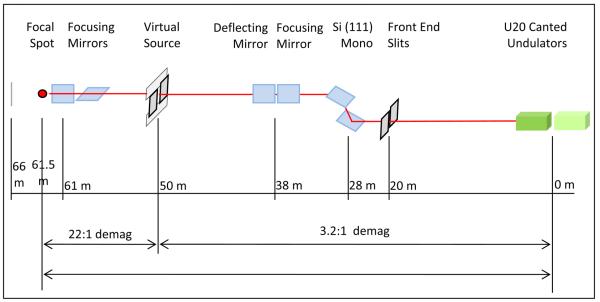
We've chosen to investigate an approach involving two-stage focusing in the horizontal direction, wherein an upstream focusing mirror delivers a focused beam at a location somewhat upstream of the sample position. At this location, an aperture is introduced to define a secondary source, whose width can be controlled easily. A secondary focusing element, which can be a mirror or a lens, thence focuses the beam onto the sample. A conceptual schematic of this configuration is shown in Figure 1. In Table I are detailed the horizontal beam widths and angular divergences calculated at selected locations along the beamline, based on use of focusing mirrors whose slope errors are assumed to be 0.1 μrad rms; the assumed source is the NSLS-II U20 undulator installed in a low-β straight section. Mirrors of such quality are judged to be available since they need not be longer than about 0.2 to 0.3 m, even if the incidence angle of the x-ray beam striking the mirror surface is as low as 3 mrad.9 Such high-quality mirrors are crucial in ensuring delivery of a beam of 1 μm cross-section to the sample; calculations undertaken using mirrors of larger slope error consistently resulted in bigger beam cross-sections, for the 0.5 m working distance (between the final mirror and the sample) which has been assumed (it is important for background suppression in MX experiments, among other reasons, to maintain this working distance to be not much smaller than this). It is just as important that there be placed in the beam path a minimum of objects, such as windows or filters, which could disrupt the x-ray wavefront, in order for such performance to be realized.
Figure 1.
Optical concept for two-stage horizontal focusing to deliver a 1 μm wide beam.
Table I.
Variation of horizontal beam width and divergence at selected locations along the beamline, all values expressed as FWHM.
| Optical Component | Location [m] | H-Size [μm] |
H-Divergence [μrad] |
|---|---|---|---|
| Source | 0 | 80 | 40 |
| Front End Slit | 20 | 220 | 15 |
| Horizontal Focusing Mirror | 38 | 490 | 15 incident |
| Secondary Source Aperture |
50 | 25 | 47 |
| Second Horiz. Focusing Mirror |
61 | 500 | 47 incident |
| Final Focal Point | 61.5 | 1.1 | 1045 |
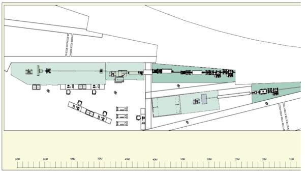
If this beamline shares a straight section sector with another beamline, each viewing separate canted undulator sources installed in the straight section, it is envisioned that the separation of the beams would be achieved through the use of a tandem pair of horizontally-deflecting mirrors installed in each beamline.2 For the beamline described above which is designed to focus the beam to 1 μm at the sample position, the first horizontal focusing mirror would be one of the tandem deflecting mirrors. This is reflected in the beamlines layout which is shown in Figure 2. Calculations have been made for the horizontal separation of the two undulator beams as a function of distance from the source, assuming that each tandem pair of horizontally-deflecting mirrors imparts an angular deflection of 16 mrad (i.e. 4 mrad incidence angle assumed for each mirror), toward the outboard direction in the case of the outboard canted undulator beamline and toward the inboard direction in the case of the inboard canted undulator beamline. Taking these into consideration (assuming the deflecting mirrors are positioned in accordance with what is shown in the beamline layout), in addition to an assumed canting angle of 2 mrad separating the two undulator sources, one predicts a horizontal separation of >44 cm at the sample location in the first (upstream) experimental station (which uses the outboard undulator beam). This would host a more conventional crystallography setup, albeit highly automated since space in this station is expected to be limited. Note that use of deflecting mirrors having an incidence angle of 4 mrad would incur an upper cutoff energy for these mirrors of about 21 keV if coated with Pt or about 17 keV if coated with Pd or Rh.
Figure 2.
Layout of canted undulator beamlines on NSLS-II experimental floor. The x-ray beam propagates from right to left, and thus the long downstream experimental station appears at far left, the shorter experimental station just upstream of it. Just below the canted undulator beamlines is a neighboring beamline that would view a bending magnet or three-pole wiggler
Performance of Beamlines
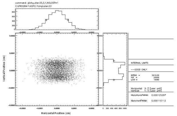
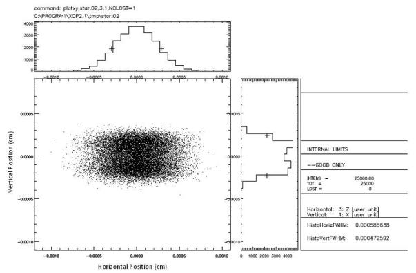
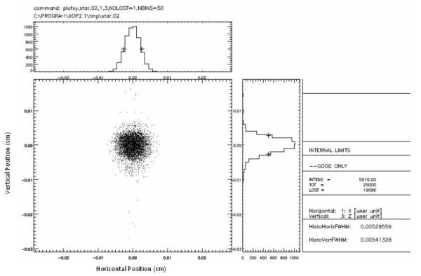
The photon beam profiles in these beamlines were studied carefully through ray-tracing analysis using the SHADOW program. These are shown in Figure 3, assuming optimal focusing by the elliptically-curved K-B mirror systems in each beamline. For the longer beamline, the first horizontal focusing mirror is at 38 m from the source, delivering its focus at a secondary source position of 50 m. The K-B mirror system consists of a vertical focusing mirror which is located at 60.5 m from the primary source and a horizontal focusing mirror which is located at 61 m; the sample position is at 61.5 m. For the shorter beamline, the K-B mirror system consists of a vertical focusing mirror which is located at 44 m from the source and a horizontal focusing mirror which is located at 45 m; the sample position is at 48 m. The nominal incidence angles for the mirrors is 3 mrad. To simulate the assumed 0.1 μrad rms mirror figure errors, the mirror surfaces were modeled as sine waves with periods ranging from 1 μm to 1 cm. A more realistic simulation would involve use of figure errors measured from an actual mirror. The FWHM dimensions of the focused beam are 1 μm (h) × 1 μm (v) for the longer beamline and 6 μm (h) × 5 μm (v) for the shorter one. The anticipated photon fluxes at 12 keV that may be attained in each beam at the focal position, based on use of canted NSLS-II U20 undulators installed in a low-β straight section and use of a Si(111) monochromator in each beamline, are about 5×10¹¹ ph/sec for the 1 μm (h) × 1 μm (v) focus beamline with the divergences at the sample position set to about 1 mrad (h) × 0.4 mrad (v), and about 1013 ph/sec for the 6 μm (h) × 5 μm (v) focus beamline with the divergences at the sample position set to about 0.1 mrad (h) × 0.1 mrad (v).
Figure 3.
Figure 3a: SHADOW ray-tracing profile of focused beam for longer beamline, incorporating two-stage horizontal focusing and one-stage vertical focusing.
Figure 3b: SHADOW ray-tracing profile of focused beam for shorter beamline, incorporating one-stage horizontal and vertical focusing.
Deserving additional consideration are the possibility and implications of a 1 μm beam size beamline being able to deliver a larger beam size (up to ~100 μm if called for) while still offering a capability of a ~1 μm beam size in the same endstation. We have modeled an approach to pursue this which embodies removal of the second horizontal focusing mirror (i.e. use one-stage focusing in the horizontal direction) and adjustments of the focal lengths of the remaining upstream horizontal focusing mirror as well as the vertical focusing mirror downstream. Only a very slight adjustment of the vertical focusing mirror's focal length is necessary, which could be achieved by tilting it slightly (e.g. an adjustment by just 25 μrad is sufficient to increase the vertical beam size to 50 μm). The beam profile determined through ray-tracing using SHADOW, which is shown in Figure 4, illustrates how an approximately 50 μm square beam could be realized through such an approach. An alternative approach which involves provisioning the long experimental station with a second K-B mirror system located farther upstream, that would substitute for the micro-focusing K-B mirror system, can be pursued as well. In either scheme, slight deflection of any of the upstream mirrors can ensure that the beam will propagate past the micro-focusing K-B mirror system (or at least past the horizontal focusing mirror of this system) without striking it, and thus the delicate micro-focusing K-B mirror system can be left undisturbed save for the possible need to tilt slightly its vertical focusing mirror.
Figure 4.
SHADOW ray-tracing profile of beam for longer beamline, realized by using single-stage horizontal focusing using the first horizontal focusing mirror alone, and slight defocusing of the vertical focusing mirror.
Summary
Tunable micro-focusing canted undulator MX beamlines can be designed in ways to achieve different objectives, to permit them to function independently with minimal potential for interference, and allow for some flexibility in the implementation of their focusing systems. We have demonstrated this conceptually by employing the properties of canted NSLS-II U20 undulators installed in a low-β straight section. Such beamlines are currently in preparation at PETRA-III and are envisioned at NSLS-II.
Acknowledgements
We gratefully acknowledge the engineering and design support which was provided by Lewis Doom and Brian Mullany of the NSLS-II Project. This work was supported by the US Dept. of Energy, the US National Institutes of Health, and the New York Structural Biology Center.
Footnotes
Publisher's Disclaimer: This is a PDF file of an unedited manuscript that has been accepted for publication. As a service to our customers we are providing this early version of the manuscript. The manuscript will undergo copyediting, typesetting, and review of the resulting proof before it is published in its final citable form. Please note that during the production process errors may be discovered which could affect the content, and all legal disclaimers that apply to the journal pertain.
This work was supported by the US DOE, the US NIH, and the New York Structural Biology Center.
References
- 1.Wakatsuki S, Belrhali H, Mitchell EP, Burmeister WP, McSweeney SM, Kahn R, Bourgeois D, Yao M, Tomizaki T, Theveneau P. J. Synchrotron Rad. 1998;5:215–221. doi: 10.1107/S0909049597018785. [DOI] [PubMed] [Google Scholar]
- 2.Fischetti RF, Yoder DW, Xu S, Stepanov S, Makarov O, Benn R, Corcoran S, Diete W, Schwoerer-Boehning M, Signorato R, Schroeder L, Berman LE, Viccaro PJ, Smith JL. AIP Conf. Proc. 2006;879:754–757. [Google Scholar]
- 3.Nurizzo D, Mairs T, Guijarro M, Rey V, Meyer J, Fajardo P, Chavanne J, Biasci J-C, McSweeney S, Mitchell E. J. Synchrotron Rad. 2006;13:227–238. doi: 10.1107/S0909049506004341. [DOI] [PubMed] [Google Scholar]
- 4.Flot D, Mairs T, Giraud T, Guijarro M, Lesourd M, Rey V, van Brussel D, Morawe C, Borel C, Hignette O, Chavanne J, Nurizzo D, McSweeney S, Mitchell E. J. Synchrotron Rad. 2010;17:107–118. doi: 10.1107/S0909049509041168. [DOI] [PMC free article] [PubMed] [Google Scholar]
- 5.De Andrade V, Thieme J, Northrup P, Yao Y, Lanzirotti A, Shen Q. Proceedings. 2010 these. [Google Scholar]
- 6.Evans G, Alianelli L, Burt M, Wagner A, Sawhney K. AIP Conf. Proc. 2006;879:836–839. [Google Scholar]
- 7.Yamamoto M, Hirata K, Hikima T, Kawano Y, Ueno G. J. Pharm. Soc. Japan. 2010;130:641–648. doi: 10.1248/yakushi.130.641. [DOI] [PubMed] [Google Scholar]
- 8.NSLS-II Source Properties and Floor Layout. 2010 posted at http://www.bnl.gov/nsls2/docs/PDF/SourceProperties.pdf.
- 9.Mimura H, Yumoto H, Matsuyama S, Sano Y, Yamamura K, Mori Y, Yabashi M, Nishino Y, Tamasaku K, Ishikawa T, Yamauchi K. Appl. Phys. Lett. 2007;90:051903. The EEM-figured mirror described in this article was 45 mm long. EEM-figured mirrors of the same (or better) quality as this one, but 0.4 m long, are now commercially available (private communication with S. Boutet and P. Montanez). [Google Scholar]


