

Abstract
Viral shells are self-assembled protein nanocontainers with remarkable material properties. They combine simplicity of construction with toughness and complex functionality. These properties make them interesting for bionanotechnology. To date we know little about how virus structure determines assembly pathways and shell mechanics. We have here used atomic force microscopy to study structural failure of the shells of the bacteriophage Φ29. We observed rigidity patterns following the symmetry of the capsid proteins. Under prolonged force exertion, we observed fracture along well-defined lines of the 2D crystal lattice. The mechanically most stable building block of the shells was a trimer. Our approach of “reverse engineering” the virus shells thus made it possible to identify stable structural intermediates. Such stable intermediates point to a hierarchy of interactions among equal building blocks correlated with distinct next-neighbor interactions. The results also demonstrate that concepts from macroscopic materials science, such as fracture, can be usefully employed in molecular engineering.
Keywords: virus capsid, virus prohead, 2D polymer, elasticity, nonlinear elasticity
Virus shells self-assemble with 2D-crystalline order, often as icosahedra. An icosahedron of 60 units is the largest shell that can be formed with equivalent building blocks (1). Shell proteins of larger viruses need conformational switches to accommodate binding in quasi-equivalent positions. Simulations for black beetle virus (BBV), southern bean mosaic virus, and human rhinovirus 14 (2) suggest that such different conformations imply a hierarchy of interaction energies.
Self-assembling closed shells are attractive as nanocontainers, e.g., for drug delivery (3). Copying evolved viral self-assembly is difficult because of complex maturation processes with transient assembly intermediates (4, 5), involving scaffolding proteins or other morphogenetic factors (6). Nevertheless, one can glimpse principles of virus construction by mechanically probing the final product. We have here mechanically “reverse engineered” viral shells by atomic force microscopy (AFM) and analyzed structural failure.
Materials are typically characterized by their linear elastic response parameters (7) and by their failure thresholds. Empirically, tensile strength is approximately 5–10% of the Young’s modulus (8). In macroscopic bulk materials, failure starts from lattice defects. In shells, in contrast, localized nonlinear instabilities (buckling) are often the dominant mode of failure (9). Viral shells are typically constructed as perfect 2D crystals, often from just one type of protein. Their mechanical response parameters are thus determined by protein–protein interactions and geometry. A continuum-material description has been remarkably successful for nanometer-sized biological structures (10, 11), in particular viral shells (12–16).
Φ29 is a double-stranded DNA bacteriophage that infects Bacillus subtilis. In the host, the viral genome is packed into a preformed shell, the prohead, by a portal motor (17–20). Proheads are prolate icosahedra (triangulation number T = 3, elongation number Q = 5; refs. 1, 18, 21), built from the protein gp8 arranged around the fivefold and quasi-sixfold symmetry centers of the icosahedron (Fig. 1). The complete prohead consists of shell, connector (gp10), scaffolding protein (gp7), and head fibers (gp8.5) (21–23). The pseudoatomic structure of Φ29 was solved with 12.7-Å resolution (22). The arrangement of gp8 in different locations results in five distinct next-neighbor interactions (Fig. 1B).
Fig. 1.

Protein organization of Φ29 proheads. (A) Three-dimensional surface representation of a fiberless Φ29 prohead reconstructed from cryoelectron microscopy (22) with superimposed triangulation net, viewed perpendicular to the fivefold axis of the particle (based on European Bioinformatics Institute, EMD-1120, EMD-1117). The prohead is 45-nm wide, 54-nm long, and elongated along one fivefold symmetry axis; wall thickness ca. 1.6 nm (18, 22, 32). (B) Schematic representation of gp8 monomer organization on the triangulation net of the Φ29 prohead: Monomers involved in intrapentameric interactions (magenta), hexamer units interacting with pentamer subunits (pink), hexamer interacting with other hexamer units (green), and equatorial subunits interacting in two additional conformations (dark-green, blue). Some monomer junctions are labeled with black circles, some edges around one pentameric plate by a yellow line.
Results and Discussion
We have here tested fracture of empty Φ29 shells with the tip of an AFM. Proheads (without gp7) were deposited on a glass surface and imaged by AFM in jumping mode (24) in buffer as described previously (13). With this mode, one can set a low tip force and avoid destruction of the shells (Fig. 2A). Particle heights (Fig. 2 C and D) agreed with earlier reports (13, 21). Pentameric plates with three to five pronounced edges were visible, both when shells were imaged on their sides (Fig. 2C) or upright (Fig. 2D). Such edges are not present in EM reconstructions of proheads (22) (Figs. 1A and 2B). Therefore, edges are not equilibrium features, but must reflect local stiffness and indentation of the shells. Force-induced deformations can be clearly seen in a cross-section (Fig. 2 D and F).
Fig. 2.

Features of proheads. (A) Low-resolution image of proheads (derivative filtered). (B) Top view of the pseudoatomic structure of Φ29. Dashed lines outline two complex pentameric features: (i) lines in blue connect the icosahedral vertices, (ii) the red pentamer is limited by the protruding domains of the monomers. The latter is similar in size to the former feature, but slightly rotated. (C) High-resolution image of a prohead lying on its side, imaging force 130 pN. (D) Same for upright prohead. The dotted line marks the cross-section shown in F. (E) Size distribution of observed pentamer sides including tip convolution (N = 12, SD = 1.6 nm). (F) Profile of the topography at the indicated cross-section, compared to undeformed shape (dashed line).
The average edge length was 20.8 ± 0.5 nm (SEM, N = 12; Fig 2E). Correction for tip broadening (10, 25) (see Materials and Methods) yields an actual length of 15 ± 1 nm. The edges of a pentamer of monomers around a fivefold vertex are unlikely candidates for the observed features because their side length is only approximately 9.5 nm (Fig. 2B). It is likely that the pentamers are limited by the so-called protruding ridge domains (22), located at the twofold quasi-symmetry axes. If true, then pentamers consist of five trimers of monomers (side length of ca. 16 nm). Five trimers thus seem to form a composite plate which is relatively easy to deform in the middle, but displays stiffer edges (Fig. 1B). The local stiffness measured by AFM reflects both local material properties and shell geometry, which determines how force is distributed in the shell. Virus shells are inhomogeneous on the scale of the protein monomers. Junctions between monomers might be soft spots (Fig. 1B), but the AFM tip with 15–20-nm radius probes the shell response averaged over several nanometers. Thus it is more likely that the observed edges correspond to hinges between plates (Fig. 1B). Direct force on an angled hinge would tend to elicit a stiff response, whereas force next to a hinge would cause motion of a plate.
Force-distance curves were reversible and linear up to approximately 2 nN. After repeated indentations, the response showed discontinuities and became irreversible. Under larger forces (3-nN, 10-ms loading cycle), virus particles deformed irreversibly. Further indentations showed a strongly decreased rigidity (Fig. 3 A and B). Images taken subsequently at lower force (< 200 pN) often showed clearly defined cracks in the shells and holes with polygonal edges (Fig. 3A).
Fig. 3.

Fracturing prohead shells. (A) Cross-section of the topography of a prohead before and after applying load to the central part of the shell. Subsequent imaging shows a hole in the shell. Loading cycle approximately 10 ms. (B) Sequence of 10-ms force-distance curves recorded from one prohead; Ni, number in the series. A discrete breaking event occurs at Ni = 5. (C) Imaging with 170 pN of maximal force. (D) Shell breaks during imaging with 370 pN. (E) Subsequent imaging at 130 pN shows fractured prohead shell. (Scale bar: 35 nm.) Scan direction: fast, horizontal; slow, top to bottom.
Exerting a point force on the virus prohead challenges the whole shell. Failure occurs not necessarily where force is applied, but either where the shell is weak, or where stress is concentrated due to geometry. We observed that the viral shells fractured along well-defined lines during repeated imaging with lower force (ca. 200–300 pN). Imaging a prohead in jumping mode involves a rapid succession of > 10,000 approaches. Probing fracture while imaging has the advantage that fractures become visible immediately. Fig. 3 C–E shows three sequentially recorded images of proheads at increasing applied forces. In the first image (ca. 170 pN), the proheads remained intact. After two to three scans at 370 pN, the shells broke, revealing a horizontal fracture line in one shell. A hexameric plate can also be seen before and after fracture. Subsequent imaging at 130 pN showed permanent damage with clearly defined fracture lines.
To find out where fractures typically occurred, we analyzed proheads with well-visible fracture lines. Most shells displayed straight fracture lines and polygonal holes (Fig. 4). Two types of damage were prevalent: indentation lines (N = 20) (Fig. 4A) and completely separated fragments (N = 53) (Fig. 4 B–D). A cross-section across an indentation line shows a (permanent) vertical displacement of approximately 3–5 nm. Straight fracture lines suggest failure along lattice lines. To identify locations of failure, we assembled a histogram of relative angles between adjoining pairs of indentation and fracture lines (Fig 4C, Upper Inset). We found distinct peaks at 60° and 120°, which implies that fracture follows the edges of the triangular segments of the icosahedral lattice. The average length of fracture lines with well-defined ends (32% of complete fracture lines) was 20 ± 1 nm (Fig 4D), which agrees with the observed edges of pentameric features in the intact shells. Although fracture patterns had different shapes, all observed edge lengths and angles were consistent with those of trimers of gp8 shell proteins. We therefore conclude that fracturing primarily took place along the borders of gp8 trimers.
Fig. 4.

Fracture patterns. (A) Fracture lines on prohead shells: (Upper Inset) enlarged feature; (Lower Inset) location of fracture on the surface lattice. (B) Same prohead as in A imaged in a further scan. The fractures have propagated to the complete displacement of a hexameric plate: (Upper Inset) enlargement of feature; (Lower Inset) lattice location of fracture. (C) Displaced triangles on another prohead: (Upper Inset) histogram of orientations of fracture lines with respect to the long axis of the prohead; (Lower Inset) lattice location of fracture. (D) Displaced triangle: (Upper Inset) histogram of the lengths of fracture lines with clearly visible ends (N = 16); (Lower Inset) lattice location of fracture. Insets in A and B are 3D rendered with a different light source position. Dashed colored frames indicate the first visual guesses (under different illumination angles of the 3D-rendered images) of the orientation of the long axis of the shells, which was then refined by matching the fracture lines into the shell lattice.
To support this conclusion, we estimated the energy dissipated during fracture. We selected force-indentation curves with clear discontinuities and otherwise linear response, also in the subsequent indentation (Fig. 3B). The area enclosed by such successive curves corresponds to a dissipated energy of approximately 10-17 J. For comparison, Reddy et al. (2) have calculated protein-pair interactions for the BBV shell of approximately 10-18 J (ca. 100 kcal/mol). The energies associated with the fracture events we observed are thus consistent with the rupture of a few next-neighbor bonds between shell proteins.
Virus shells are held together by the interactions between the shell proteins, with possible support from the enclosed nucleic acid (26). The pattern of failure we found indicates that the Φ29 shells are constructed in a way that results in a hierarchy of interaction energies with the interactions around the threefold symmetry axis in the triangular faces the strongest. Such a hierarchy may be a fundamental principle of virus shell construction. Trimers have been suggested as building blocks in other viruses (27–29). Covalent cross-linking around the threefold axis occurs (e.g., in HK97) (4, 30–32). In T7, neighboring subunits get interlocked by domain swapping around the threefold axes (33). Trimers of monomers thus also appear to be the building blocks from which the elongated Φ29 shell is assembled.
Trimers interact in four distinct geometries (Fig 1B). To probe for further hierarchy, we classified the observed fracture lines (Figs. 1 and 4). We found (Fig. 5) that the bonds between proteins in the twofold symmetry positions on the equatorial belt failed nearly twice as often as the bonds within the end caps. This outcome could simply reflect geometry. The equatorial region is cylindrical, whereas the end caps have spherical curvature. Buckling will thus occur in the equatorial region and fracture should be more likely. It is also known, however, that proheads are built with the help of a scaffolding protein (gp7) (23). Without gp7, the shells assemble mainly into T = 3 icosahedral particles (34). The formation of the equatorial belt involves the formation of skewed hexamers, thus possibly diminishing the trimeric interaction strength in the equator, which could also cause failure in the equatorial region.
Fig. 5.

Normalized failure rates of trimer interactions. Interaction pairs one to four represent the magenta-pink, light-green–light-green, dark-green–light-green, and blue–blue interactions between gp8 trimers (Fig. 1B) in that sequence. Plotted are relative frequencies of observation of complete fracture lines only (triangles), and of any event, fracture, or indentation (circles). Error bars are normalized counting errors ( ).
).
In conclusion, we found that Φ29 virus shells suffer structural failure under high stress in a way that shows analogies to the fracture of macroscopic solid shells. Failure location is likely due both to geometry (i.e., localized buckling) and to weak spots in the shells. Molecular architecture manifests itself in the fact that fracture lines follow the edges of molecular building blocks. It is intriguing that a hierarchy of structure becomes evident in mechanical response. Although initial assembly takes place in the presence of scaffolding protein, followed by maturation, hierarchy may also play a crucial role in assembly. The lessons learned here about how the interplay between molecular structure and geometry determines the mechanical properties and the failure thresholds of the virus shells should help to guide our design of technical self-assembling nanocontainers.
Materials and Methods
Virus Preparation.
The proheads were purified as described in ref. 18. The AFM samples were prepared and treated as described in ref. 13. All experiments were performed in PBS (pH = 7.4) buffer.
AFM Imaging.
Most images were made with a maximal force of approximately 100 pN, which did vary from experiment to experiment by about 50 pN depending on the details of the cantilever—sample engagement. Because the contact force is small and the contact area is only a few nanometers in diameter, we do not expect the tip radius to have a major influence. All images were made with an AFM (Nanotec Electronica) operated in jumping mode (24). In this mode, the AFM executes a force-distance curve at every point of the topographical image in a raster scan fashion. The maximum normal force exerted by the tip on the sample is set as a parameter. In that way the maximal normal force applied to every scanned sample point is constant and known. The tip is moved in the lateral direction only when it is out of contact with the sample, so that shear forces are minimized. The cantilevers used in our experiments (OMCL-RC800PSA, Olympus) had conical tips with spherical apices with radii of approximately 17 nm (SD = 5 nm, N = 14). The cantilever spring constants were calibrated using the method of Sader et al. (35). Both topographical images and the corresponding normal-force maps were recorded. Images were processed with WSxM software (Nanotec Electronica) (36).
Correction for Image Dilation.
Due to the finite radius of the AFM tip, sample features appear laterally dilated in the images, whereas heights are measured correctly. The AFM tip in contact with a virus prohead resting on a flat surface can be approximated by two spheres in contact with radius Rt (tip) and r0 (virus prohead) as long as the depth of features imaged on top of the proheads remains small compared to the tip radius (Fig. 6A). From simple geometrical considerations, the apparent broadening half-width wh can be expressed as a function of the distance h from the top of the shell to the tip position, at which the width is measured as
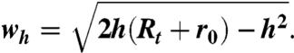 |
[1] |
Actual tip radii were determined from the height profiles of undeformed shells, recorded across their midsections, by comparing heights (known to be 45 nm) to apparent widths at small distances h where the conical shape of the tip does not contribute much to the broadening of the measured profile. With all other geometrical parameters known, we can estimate the actual lengths of the observed edges on the shells from the dilated apparent lengths. We perform this estimate by considering the apparent radius of a cross-section through the shells at the height at which the features were observed on the capsids surfaces, typically at a height of 1–2 nm below the top of the shells. This radius corresponds to the apparent width wh in Eq. 1. Typically, the dilation of the radius amounts to 2–3 nm. The actual length of a pentameric side areal can then be calculated from the apparent length ameasured and the actual radius of the cross-section Rreal (Fig. 6B) as
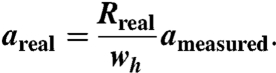 |
[2] |
Fig. 6.

Correction for lateral dilation. (A) Schematic representation of side view of two spheres in contact. (B) Top view of dilated and actual pentamers inscribed in a circle corresponding to a dilated and undilated horizontal cross-section, respectively, at height h through a sphere with radius r0.
Data Analysis.
To relate the features observed on the virus proheads to their molecular structure, we use a mesh of triangles as a model for the virus shell. The surface of one triangle is tiled by three trapezoids representing the capsid protein monomers (Fig. 1B). All proheads analyzed were attached to the glass surface parallel to their long axis. The schematic mesh (including the tip dilation effect) was matched by eye with the AFM images determining location and orientation on the surface (dashed frames in Fig. 4). Two or more independent observers found only negligible differences in these parameters. Rotation of the shell around its long axis exposes different views of the upper surface features. Because the long axis is the axis of fivefold symmetry, a rotation of 72° is a symmetry operation. Thus we only needed to test angles between 0° and 72° for a best fit of lattice lines to the observed fracture lines. In fact, only four different orientations were found to accommodate all observed lines well, the orientation with one equatorial hexagon pointing up and angles of 18°, 36°, and 54° with respect to this orientation. Two of those four positions, respectively, are trivially related by flipping the particle upside down. Thus the virus shells appeared to have two preferred attachment geometries.
Fracture lines were identified and classified from the AFM images in detail as follows: First, the orientation of the prohead in the x–y plane was obtained as described above. Lines were then drawn by hand following the visible fracture lines over a 3D-rendered topographical image using a certain illumination light angle for the rendering. Then the procedure was repeated with different light angles, which typically slightly altered the lengths and orientations of the drawn lines. Every actual fracture line on a shell was thus identified by more than one line, which were subsequently averaged to minimize the effect of illumination artefacts in the rendering procedure. The resulting pattern was matched to the triangular surface mesh by trying different rotation angles around the long axis, and the best fit was chosen (Fig. 4, Lower Insets). Lines across the shell surface were of two types, fracture lines where clear protein–protein separation had occurred along holes and deep cracks, and lines which looked like sharp edges on the shells, possibly without complete protein–protein separation, which we call “indentation lines”. The indentation lines occurred less frequently than the first type, but most of the indentation lines progressed into fracture lines during repeated imaging. In total, the lines (both fracture and indentation) that matched lattice lines in the triangular mesh well were 75% of the total number (N = 92, from 13 different proheads) of all observed linear features on the broken prohead surfaces. The remaining fracture lines which could not be clearly classified in the lattice framework were not considered in the further analysis.
The normalization of the count rates for a particular type of trimer–trimer contact line plotted in Fig. 5 was performed by dividing the frequency of occurrence of that particular contact within the subarea of the capsid surface probed (i.e., a part of the top half of the proheads) by the AFM tip in the two attachment configurations observed. The average opening angle of our tips was 64° ± 11° (14 tips used) and determines the fraction of the top half of the proheads actually contacted by the tip. The relative occurrence of interaction types one to four determined in this geometry is 45%, 10%, 25%, and 20%, respectively.
Acknowledgments.
This work was part of the research program of the Stichting voor Fundamenteel Onderzoek der Materie, which is financially supported by the Nederlandse Organisatie voor Wetenschappelijk Onderzoek (NWO), and by a Vidi and Vici grant to G.J.L.W. from the NWO. This work was partly financed by S-2009/MAT-1507 from the Comunidad de Madrid, Consolider CSD2007-00010, and BFU2008-02328/BMC from the Spanish Ministry of Science and Innovation (Ministerio de Ciencia e Innovacion) (J.L.C.). C.F.S. was furthermore supported by the German Science Foundation (Deutsche Forschungsgemeinschaft) Research Center Molecular Physiology of the Brain.
Footnotes
The authors declare no conflict of interest.
This article is a PNAS Direct Submission.
References
- 1.Caspar DLD, Klug A. Physical principles in construction of regular viruses. Cold Spring Harb Symp Quant Biol. 1962;27:1–24. doi: 10.1101/sqb.1962.027.001.005. [DOI] [PubMed] [Google Scholar]
- 2.Reddy VS, et al. Energetics of quasiequivalence: Computational analysis of protein-protein interactions in icosahedral viruses. Biophys J. 1998;74:546–558. doi: 10.1016/S0006-3495(98)77813-0. [DOI] [PMC free article] [PubMed] [Google Scholar]
- 3.Douglas T, Young M. Viruses: Making friends with old foes. Science. 2006;312:873–875. doi: 10.1126/science.1123223. [DOI] [PubMed] [Google Scholar]
- 4.Fokine A, et al. Structural and functional similarities between the capsid proteins of bacteriophages T4 and HK97 point to a common ancestry. Proc Natl Acad Sci USA. 2005;102:7163–7168. doi: 10.1073/pnas.0502164102. [DOI] [PMC free article] [PubMed] [Google Scholar]
- 5.Johnson JE. Virus particle maturation: Insights into elegantly programmed nanomachines. Curr Opin Struct Biol. 2010;20:210–216. doi: 10.1016/j.sbi.2010.01.004. [DOI] [PMC free article] [PubMed] [Google Scholar]
- 6.Casjens S, Chiu W, Burnett RM, Garcea RL. Principles of virion structure, function and assembly. In: Chiu W, Burnett RM, Garcea RL, editors. Structural Biology of Viruses. New York: Oxford Univ Press; 1997. pp. 38–79. [Google Scholar]
- 7.Landau LD, Lifshitz EM, Kosevich M, Pitaevskii LP. Theory of Elasticity. 3rd Ed. Oxford: Pergamon; 1986. [Google Scholar]
- 8.Ugural AC, Fenster SK. Advanced Strength and Applied Elasticity. 5th Ed. Upper Saddle River: Prentice Hall; 2011. pp. 181–218. [Google Scholar]
- 9.Calladine CR. Understanding imperfection-sensitivity in the buckling of thin-walled shells. Thin Wall Struct. 1995;23:215–235. [Google Scholar]
- 10.de Pablo PJ, Schaap IAT, MacKintosh FC, Schmidt CF. Deformation and collapse of microtubules on the nanometer scale. Phys Rev Lett. 2003;91:098101. doi: 10.1103/PhysRevLett.91.098101. [DOI] [PubMed] [Google Scholar]
- 11.Graveland-Bikker JF, Schaap IAT, Schmidt CF, de Kruif CG. Structural and mechanical study of a self-assembling protein nanotube. Nano Lett. 2006;6:616–621. doi: 10.1021/nl052205h. [DOI] [PubMed] [Google Scholar]
- 12.Arkhipov A, Roos WH, Wuite GJ, Schulten K. Elucidating the mechanism behind irreversible deformation of viral capsids. Biophys J. 2009;97:2061–2069. doi: 10.1016/j.bpj.2009.07.039. [DOI] [PMC free article] [PubMed] [Google Scholar]
- 13.Ivanovska IL, et al. Bacteriophage capsids: Tough nanoshells with complex elastic properties. Proc Natl Acad Sci USA. 2004;101:7600–7605. doi: 10.1073/pnas.0308198101. [DOI] [PMC free article] [PubMed] [Google Scholar]
- 14.Klug WS, et al. Failure of viral shells. Phys Rev Lett. 2006;97:228101. doi: 10.1103/PhysRevLett.97.228101. [DOI] [PubMed] [Google Scholar]
- 15.Michel JP, et al. Nanoindentation studies of full and empty viral capsids and the effects of capsid protein mutations on elasticity and strength. Proc Natl Acad Sci USA. 2006;103:6184–6189. doi: 10.1073/pnas.0601744103. [DOI] [PMC free article] [PubMed] [Google Scholar]
- 16.Roos WH, Bruinsma R, Wuite GJL. Physical virology. Nat Phys. 2010;6:733–743. [Google Scholar]
- 17.Guasch A, et al. Detailed architecture of a DNA translocating machine: The high-resolution structure of the bacteriophage phi 29 connector particle. J Mol Biol. 2002;315:663–676. doi: 10.1006/jmbi.2001.5278. [DOI] [PubMed] [Google Scholar]
- 18.Ibarra B, et al. Topology of the components of the DNA packaging machinery in the phage phi 29 prohead. J Mol Biol. 2000;298:807–815. doi: 10.1006/jmbi.2000.3712. [DOI] [PubMed] [Google Scholar]
- 19.Simpson AA, et al. Structure of the bacteriophage phi 29 DNA packaging motor. Nature. 2000;408:745–750. doi: 10.1038/35047129. [DOI] [PMC free article] [PubMed] [Google Scholar]
- 20.Valpuesta JM, Carrascosa JL, Henderson R. Analysis of electron-microscope images and electron-diffraction patterns of thin-crystals of 029-connectors in ice. J Mol Biol. 1994;240:281–287. doi: 10.1006/jmbi.1994.1445. [DOI] [PubMed] [Google Scholar]
- 21.Tao YZ, et al. Assembly of a tailed bacterial virus and its genome release studied in three dimensions. Cell. 1998;95:431–437. doi: 10.1016/s0092-8674(00)81773-0. [DOI] [PMC free article] [PubMed] [Google Scholar]
- 22.Morais MC, et al. Conservation of the capsid structure in tailed dsDNA bacteriophages: The pseudoatomic structure of phi 29. Mol Cell. 2005;18:149–159. doi: 10.1016/j.molcel.2005.03.013. [DOI] [PubMed] [Google Scholar]
- 23.Morais MC, et al. Bacteriophage phi 29 scaffolding protein gp7 before and after prohead assembly. Nat Struct Biol. 2003;10:572–576. doi: 10.1038/nsb939. [DOI] [PubMed] [Google Scholar]
- 24.de Pablo PJ, Colchero J, Gomez-Herrero J, Baro AM. Jumping mode scanning force microscopy. Appl Phys Lett. 1998;73:3300–3302. [Google Scholar]
- 25.Villarubia JS. Algorithms for scanned probe microscope image simulation, surface reconstruction, and tip estimation. J Res Natl Inst Stand Technol. 1997;102:425–454. doi: 10.6028/jres.102.030. [DOI] [PMC free article] [PubMed] [Google Scholar]
- 26.Carrasco C, et al. DNA-mediated anisotropic mechanical reinforcement of a virus. Proc Natl Acad Sci USA. 2006;103:13706–13711. doi: 10.1073/pnas.0601881103. [DOI] [PMC free article] [PubMed] [Google Scholar]
- 27.Chen JZ, et al. Molecular interactions in rotavirus assembly and uncoating seen by high-resolution cryo-EM. Proc Natl Acad Sci USA. 2009;106:10644–10648. doi: 10.1073/pnas.0904024106. [DOI] [PMC free article] [PubMed] [Google Scholar]
- 28.Fabry CM, et al. A quasi-atomic model of human adenovirus type 5 capsid. EMBO J. 2005;24:1645–1654. doi: 10.1038/sj.emboj.7600653. [DOI] [PMC free article] [PubMed] [Google Scholar]
- 29.Luque D, et al. Infectious bursal disease virus capsid assembly and maturation by structural rearrangements of a transient molecular switch. J Virol. 2007;81:6869–6878. doi: 10.1128/JVI.00077-07. [DOI] [PMC free article] [PubMed] [Google Scholar]
- 30.Duda RL, et al. Structural transitions during bacteriophage-Hk97 head assembly. J Mol Biol. 1995;247:618–635. doi: 10.1006/jmbi.1995.0168. [DOI] [PubMed] [Google Scholar]
- 31.Popa MP, McKelvey TA, Hempel J, Hendrix RW. Bacteriophage-Hk97 structure—wholesale covalent cross-linking between the major head shell subunits. J Virol. 1991;65:3227–3237. doi: 10.1128/jvi.65.6.3227-3237.1991. [DOI] [PMC free article] [PubMed] [Google Scholar]
- 32.Wikoff WR, Johnson JE. Virus assembly: Imaging a molecular machine. Curr Biol. 1999;9:R296–R300. doi: 10.1016/s0960-9822(99)80183-3. [DOI] [PubMed] [Google Scholar]
- 33.Agirrezabala X, et al. Quasi-atomic model of bacteriophage T7 procapsid shell: Insights into the structure and evolution of a basic fold. Structure. 2007;15:461–472. doi: 10.1016/j.str.2007.03.004. [DOI] [PubMed] [Google Scholar]
- 34.Choi KH, Morais MC, Anderson DL, Rossmann MG. Determinants of bacteriophage phi 29 head morphology. Structure. 2006;14:1723–1727. doi: 10.1016/j.str.2006.09.007. [DOI] [PubMed] [Google Scholar]
- 35.Sader JE, Larson I, Mulvaney P, White LR. Method for the calibration of atomic-force microscope cantilevers. Rev Sci Instrum. 1995;66:3789–3798. [Google Scholar]
- 36.Horcas I, et al. WSXM: A software for scanning probe microscopy and a tool for nanotechnology. Rev Sci Instrum. 2007;78:013705. doi: 10.1063/1.2432410. [DOI] [PubMed] [Google Scholar]