

Abstract
We report a portable lensless on-chip microscope that can achieve <1 μm resolution over a wide field-of-view of ~24 mm2 without the use of any mechanical scanning. This compact on-chip microscope weighs ~95 g and is based on partially coherent digital in-line holography. Multiple fiber-optic waveguides are butt-coupled to light emitting diodes, which are controlled by a low-cost micro-controller to sequentially illuminate the sample. The resulting lensfree holograms are then captured by a digital sensor-array and are rapidly processed using a pixel super-resolution algorithm to generate much higher resolution holographic images (both phase and amplitude) of the objects. This wide-field and high-resolution on-chip microscope, being compact and light-weight, would be important for global health problems such as diagnosis of infectious diseases in remote locations. Toward this end, we validate the performance of this field-portable microscope by imaging human malaria parasites (Plasmodium falciparum) in thin blood smears. Our results constitute the first-time that a lensfree on-chip microscope has successfully imaged malaria parasites.
Optical microscopy is still a vital tool for various blood tests and diagnosis of infectious diseases such as malaria and tuberculosis. Although existing optical microscopes offer powerful solutions for several application needs, they are in general not suitable for field-use in resource-limited settings where the main requirements are cost-effectiveness, portability and robustness, while still achieving a decent imaging performance, which is primarily determined by requirements of the application of interest.
Over the last few years considerable effort has been focused toward designing devices which satisfy these unique requirements for field-use.1–6 Along the same lines, here we report a holographic lensless microscope (see Fig. 1) which achieves a wide field-of-view (FOV) of ~24 mm2 together with a resolution of <1 μm. At the heart of this field-portable microscope lies an array of 23 multi-mode fiber-optic waveguides (Fig. 1), simply arranged along a line with no gaps in between. Every fiber in this array is butt-coupled to an individual light-emitting diode (LED) without the use of any coupling optics or lenses. Using a low-cost digital micro-processor, these 23 LEDs are sequentially turned on such that the sample is illuminated by a single fiber at a given moment in time, creating lensfree transmission holograms of the objects at the sensor-array (Fig. 1). Because these holograms are captured using an in-line geometry, the scattered light from the objects interferes with the unscattered background light, which makes the entire microscopy platform much more compact and mechanically robust without the need for excessive alignment (especially when compared to an off-axis geometry). With each individual fiber illumination, a different lensfree hologram that is shifted with respect to others is acquired, and this permits us to utilize a pixel super-resolution algorithm6–10 to create a much higher resolution hologram of the same scene without trading off the wide FOV. This compact microscopy platform weighing only ~95 g can achieve <1 μm resolution over 24 mm2 FOV (without the use of any mechanical scanning or optical components such as lenses), which is >50 fold larger than the FOV of an objective-lens with comparable resolution. Another important feature of this lensfree microscope is that since it utilizes large core fiber-optic cables with a diameter of >0.1 mm, there is no major alignment requirement in its architecture making it quite robust and easy to use. Further, because of the holographic nature of image formation, we can reconstruct both amplitude and phase images of the objects, where the latter can especially be of use for better visualization of weakly scattering objects such as parasites or pathogens. To demonstrate the performance of this lensless holographic super-resolution microscope, we imaged micro-structures patterned on glass as well as malaria parasites (Plasmodium falciparum) in standard smears of infected human red blood cells.
Fig. 1.

A photograph (left) and a schematic diagram (right) of the lensfree super-resolution microscope (weighing ~95 g) are shown. 23 individual multi-mode fiber-optic cables are butt-coupled to 23 LEDs without the use of any lenses or other opto-mechanical components. Using an inexpensive micro-controller, each LED is sequentially turned on and is used as an illumination source to create lensfree holograms of the objects on a CMOS sensor-array. These recorded lensfree holograms are shifted with respect to each other and can be rapidly processed using a pixel super-resolution algorithm to create transmission images of the objects achieving <1 μm resolution over >24 mm2 FOV which is >50× larger than a conventional microscope objective-lens having a similar resolution level. The LEDs and the CMOS sensor chip are both powered through USB connections from the side.
A schematic diagram of our lensless holographic microscope, together with a photograph of its prototype are shown in Fig. 1. In our lensless microscope architecture, each LED (OSRAM TOPLED SuperRed, 633 nm) is butt-coupled to an individual multi-mode fiber-optic waveguide with a core diameter of 105 μm, i.e., the free end of each fiber acts as a large pinhole through which the sample is illuminated. The bandwidth of each LED is ~15–20 nm, but it is filtered down to ~10 nm using a simple colour filter (see Fig. 1) which relatively increases the temporal coherence of the source to claim an effective numerical aperture (NA) of ~0.4. The object slide to be imaged (e.g., a blood smear) is placed directly atop the protective glass of the image sensor, i.e., approximately z ≈ 0.7 mm away from the active area of the sensor chip (Aptina MT9P031I12STM; complementary metal-oxide-semiconductor—CMOS), and a distance of 3–6 cm away from the fiber-optic cables. Therefore, the maximum angle from the source to the edges of the sensor is <2–3° such that all the cells/objects that are placed at z = 0.7 mm effectively see the same illumination. The free ends of all these 23 fiber-optic waveguides are bundled together in the form of a line (see Fig. 1) with no gaps in between. Using a simple and cost-effective micro-controller (Atmel ATmega8515, ~3 USD per piece) each one of the LEDs is sequentially turned on, and a lensfree holographic image is captured by the sensor with a short exposure time of ~30 ms per image. As the partially coherent LED light from the fiber-end propagates toward the sample, it develops a sufficiently large spatial coherence diameter such that the scattered light from each micro-object can coherently interfere with the unperturbed portion of the illumination, forming a holographic interference pattern on the CMOS sensor. A typical example of such a lensfree hologram acquired with a single LED illumination is shown in Fig. 2 left image.
Fig. 2.
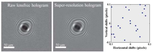
A raw lensfree hologram (left image) captured by the sensorarray (see Fig. 1) is undersampled due to relatively large pixel size (~2.2 μm) at the sensor chip. Multiple shifted lensfree holograms are processed through our pixel super-resolution algorithm to generate a much higher resolution hologram where spatial aliasing is resolved as illustrated in the middle image. Sub-pixel shift amounts between different frames are also shown on the right plot with blue dots. Note that no prior information of these lateral shift amounts is required as they can be numerically estimated from the acquired series of lensfree holograms.
As different LEDs (each of which is butt-coupled to a specific fiber within the linear array) are sequentially turned on and off, shifted versions of the same hologram are sampled at the CMOS sensor-array. It is quite interesting to note that these hologram shifts at the detector plane are around two orders of magnitude smaller than the physical distances between the centers of the fiber-ends. More importantly, no prior information of these lateral distances or shift amounts is required as they can be numerically estimated from the acquired series of lensfree holograms. In addition, these lateral shifts do not need to be regularly spaced in x–y plane, and actually can be randomly placed, making the performance of this microscope quite robust and insensitive to potential mechanical misalignments during the lifetime of the instrument. In our holographic pixel super-resolution approach,6,7 integer pixel shifts between different holograms do not offer additional information and are digitally removed. Sub-pixel shifts, on the other hand, allow reconstruction of high-frequency fringes (after appropriate processing) which are normally under-sampled in a single raw hologram as illustrated in Fig. 2 left image. The integer pixel shifts to be removed are calculated by cross-correlation of raw lensfree holograms, and the remaining sub-pixel shifts are then calculated by an iterative gradient based shift estimation method.8 These multiple sub-pixel shifted holograms are then input to a pixel super-resolution algorithm,6–9 which creates a single high-resolution hologram as illustrated in Fig. 2 middle image, resolving higher spatial frequency oscillations that do not exist in the raw lensfree holograms. This computation involves iterative optimization of a cost-function that is defined by the square of the absolute error between the target super-resolved hologram and the measured raw lensfree holograms. This cost-function also includes a regularization term6 which penalizes higher frequencies to avoid potential artifacts in the reconstructed images.
To investigate the performance of our holographic super-resolution microscope, we imaged micro-patterns etched on a glass slide using focused ion beam (FIB) milling. Ideally, these etched patterns are phase-only objects with an optical phase that is proportional to the etching depth. For this micro-pattern, Fig. 2 illustrates a raw lensfree hologram and its super-resolved version that is obtained using our super-resolution microscope shown in Fig. 1. The additional fringes of the super-resolved hologram that are now clearly visible when compared to the raw hologram translate to a higher effective numerical aperture,3,6 i.e., a higher maximal scattering angle for which the holographic fringes can be appropriately sampled. This increased numerical aperture in turn translates to a higher spatial resolution in the reconstructed microscopic images. For the same object shown in Fig. 2, Fig. 3 compares the phase images that are reconstructed by processing this super-resolution hologram as well as a single raw lensfree hologram, which clearly illustrates the higher resolving power of our super-resolution microscope compared to a single hologram. The recovered phase images in both cases are negative, as expected from a pattern etched in glass. This digital reconstruction step involves an iterative object-support constrained phase recovery algorithm3,4,6 which effectively removes the twin image artifact of in-line holography and allows the recovery of the object image (both amplitude and phase) taking typically ~10–15 iterations (<1 s) to converge using, e.g., a graphics processing unit (GPU). The spacing between the letters U and C in this etched pattern is 1 μm, and the two letters are clearly resolved using our super-resolution microscope indicating sub-micron resolution. To further quantify this, we have also plotted the recovered phase profile across the letter L and its 1D spatial derivative, which is an indicator of the “edge-response” of our microscope. As illustrated in Fig. 3, the full-width-half-maximum (FWHM) of this phase derivative profile is ~0.8 μm, which further supports that our resolution is sub-micron.
Fig. 3.
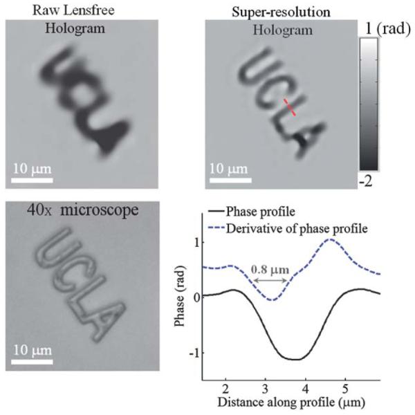
A comparison of reconstructed phase images that are acquired using a raw lensfree hologram vs. the super-resolution hologram shown in Fig. 2 is provided for a micro-pattern that is etched in glass. A 40× bright-field microscope image of the same pattern is also provided for comparison. A cross-section of the phase image across the letter “L” and its 1D spatial derivative demonstrates the resolution to be <1 μm. The spacing between the letters “U” and “C” in this etched pattern is 1 μm, and the two letters are clearly resolved using the super-resolution microscope further supporting sub-micron resolution.
The portable lensfree microscope presented here is aimed toward field-use for disease diagnostics, blood tests, water quality tracking, and other applications where optical microscopy is commonly used. For these tasks, a wide FOV as we have demonstrated in this work becomes highly desirable for rapidly screening large sample volumes for, e.g., detection of characteristic signatures of parasites. In the case of detection of malaria in blood smears and for determining the percentage of infected red blood cells, several different fields-of-view of a typical bright-field microscope must be examined to overcome statistical fluctuations. The holographic super-resolution microscope presented here has an FOV of ~24 mm2, which is >150 fold larger than a typical 40× bright-field microscope FOV, with no aberrations across the entire FOV,6 and therefore a single microscope image with such a wide FOV would be sufficient for the same purpose. In addition, the digital nature of this holographic microscope (with phase and amplitude images) could possibly permit automation of malaria diagnosis by processing the acquired lensfree images.
As an initial step toward this goal, we have tested our holographic microscope for its ability to resolve malaria parasites in standard blood smears. In Fig. 4, sample images of human red blood cells in a thin smear are shown, where the parasites (Plasmodium falciparum) were stained with the standard Giemsa stain. Similar to Fig. 2, multiple shifted holograms of the blood smear were obtained using our portable microscope shown in Fig. 1 and were processed to create a single high-resolution hologram of the blood smear. This super-resolution hologram is then processed using an iterative phase recovery technique3,4,6 as discussed earlier to reconstruct the amplitude and phase images of the blood cells as illustrated in Fig. 4. For comparison purposes, bright-field microscope images obtained with a 40× objective-lens (NA = 0.65) are also shown in the same figure. These reconstructed images show that the infected red blood cells can be identified using the combination of amplitude and phase images of our holographic super-resolution microscope, and can be distinguished from uninfected red blood cells which appear spatially more homogeneous in both amplitude and phase images. These results are quite promising for future studies that will aim to test this portable microscope for automated diagnosis of malaria in disease-endemic locations.
Fig. 4.

Imaging of red blood cells infected with malaria parasites (Plasmodium falciparum) in a standard thin blood smear is demonstrated using our lensfree super-resolution microscope shown in Fig. 1. The parasites are clearly visible in both amplitude and phase images of our lensfree microscope. 40× objective (NA = 0.65) bright-field microscope images of the same samples are also provided for comparison purposes, where the infected cells are marked with an arrow.
To address the computation need of our lensless microscopy platform in field settings one possibility is that compressed versions of our raw holograms can be transmitted to a central PC station for rapid processing using e.g., a GPU, after which the reconstruction results can be sent back through an existing wireless network. On a related note, in an earlier work4 we showed that a raw lensfree hologram corresponding to an imaging FOV of ~1 mm2 can be compressed down to <0.1 MB without an apparent loss of spatial resolution. Another possibility toward this end could be to locally perform the computation using a simple low-cost laptop or even a smart-phone without the use of any wireless transmission.
One limitation of the presented technique is that since it operates in transmission mode, it cannot image objects which are optically dense causing severe distortions to the background light that serves as the reference beam in our in-line holographic imaging geometry. For such optically dense objects of interest (such as histopathology slides), reflection based geometry, rather than transmission, would be more suitable.
Before concluding, we should also emphasize that the presented lensfree super-resolution microscope in its current transmission mode can also be modified with cost-effective components such as thin polarizers and birefringent crystals to conduct high-resolution differential interference contrast (DIC) microscopy3,11 or polarization microscopy12 for on-chip imaging of, e.g., birefringent cells/objects over a large field-of-view.
In conclusion, we reported a lensless holographic super-resolution microscope which is quite robust, easy to use, portable (~95 g) and cost-effective, achieving a resolution of <1 μm over 24 mm2 FOV. We also demonstrated the capabilities of this lensfree microscope by imaging fabricated micro-patterns and human malaria parasites in thin blood smears. These results constitute the first-time that a lensfree on-chip microscope successfully imaged malaria parasites.
Acknowledgements
A. Ozcan gratefully acknowledges the support of NSF CAREER Award, the ONR Young Investigator Award 2009 and the NIH Director’s New Innovator Award DP2OD006427 from the Office of The Director, NIH. The authors also acknowledge the support of the Gates Foundation, Vodafone Americas Foundation, and NSF BISH program (under Awards # 0754880 and 0930501). The authors also acknowledge Derek Tseng of UCLA for his assistance with the figures, and Kong Wai Cheung of UC Davis for maintenance of Plasmodium falciparum cultures and for hisassistance with preparation of thin smears of infected red blood cells
Notes and references
- 1.Breslauer DN, Maamari RN, Switz NA, Lam WA, Fletcher DA. PLoS One. 2009;4:e6320. doi: 10.1371/journal.pone.0006320. [DOI] [PMC free article] [PubMed] [Google Scholar]
- 2.Goddard G, Martin JC, Graves SW, Kaduchak G. Cytometry, Part A. 2006;69:66–74. doi: 10.1002/cyto.a.20205. [DOI] [PubMed] [Google Scholar]
- 3.Mudanyali O, Tseng D, Oh C, Isikman SO, Sencan I, Bishara W, Oztoprak C, Seo S, Khademhosseini B, Ozcan A. Lab Chip. 2010;10:1417. doi: 10.1039/c000453g. [DOI] [PMC free article] [PubMed] [Google Scholar]
- 4.Tseng D, Mudanyali O, Oztoprak C, Isikman SO, Sencan I, Yaglidere O, Ozcan A. Lab Chip. 2010;10:1787. doi: 10.1039/c003477k. [DOI] [PMC free article] [PubMed] [Google Scholar]
- 5.Miller AR, Davis GL, Oden ZM, Razavi MR, Fateh A, Ghazanfari M, Abdolrahimi F, Poorazar S, Sakhaie F, Olsen RJ, Bahrmand AR, Pierce MC, Graviss EA, Richards-Kortum R. PLoS One. 2010;5(8):e11890. doi: 10.1371/journal.pone.0011890. [DOI] [PMC free article] [PubMed] [Google Scholar]
- 6.Bishara W, Su T, Coskun AF, Ozcan A. Opt. Express. 2010;18:11181. doi: 10.1364/OE.18.011181. [DOI] [PMC free article] [PubMed] [Google Scholar]
- 7.Bishara W, Zhu H, Ozcan A. Opt. Express. 2010;18:27499–27510. doi: 10.1364/OE.18.027499. [DOI] [PMC free article] [PubMed] [Google Scholar]
- 8.Hardie R, Barnard K, Armstrong E. IEEE Trans. Image Process. 1997;6(12):1621–1633. doi: 10.1109/83.650116. [DOI] [PubMed] [Google Scholar]
- 9.Park SC, Park MK, Kang MG. IEEE Signal Process. Mag. 2003;20(3):21–36. [Google Scholar]
- 10.Woods NA, Galatsanos NP, Katsaggelos AK. IEEE Trans. Image Process. 2006;15(1):201–213. doi: 10.1109/tip.2005.860355. [DOI] [PubMed] [Google Scholar]
- 11.Oh C, Isikman SO, Khademhosseini B, Ozcan A. Opt. Express. 2010;18(5):4717–4726. doi: 10.1364/OE.18.004717. [DOI] [PMC free article] [PubMed] [Google Scholar]
- 12.Oh C, Isikman S, Ozcan A. Conference on Laser Electro-Optics: Applications, OSA Technical Digest; Optical Society of America; 2010. [Google Scholar]