Abstract
The design and fabrication of an epidural spinal cord implant using a parylene-based microelectrode array is presented. Rats with hindlimb paralysis from a complete spinal cord transection were implanted with the device and studied for up to eight weeks, where we have demonstrated recovery of hindlimb stepping functionality through pulsed stimulation. The microelectrode array allows for a high degree of freedom and specificity in selecting the site of stimulation compared to wire-based implants, and triggers varied biological responses that can lead to an increased understanding of the spinal cord and locomotion recovery for victims of spinal cord injury.
INTRODUCTION
Spinal cord injury is estimated to afflict over 1.3 million individuals in the US alone, while paralysis affects over 5 million [1]. The debilitating nature of paralysis has a profound affect on quality of life, making research into even partially effective treatment a highly desirable goal by the scientific community.
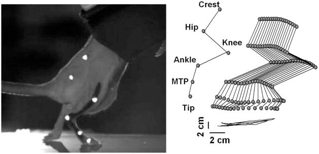
Fortunately, experimental research on animals has shown that some degree of locomotion recovery is possible; in particular, epidural spinal cord stimulation in rats has been shown to induce stepping [2,3]. In these studies, rats were implanted with up to eight wire electrodes fed from a headplug down the neck and to the spinal cord, and during testing they were suspended in a jacket such that their hindlimbs sit on a treadmill (as in Fig. 5). Around two weeks after the spinal cord injury, clear stepping patterns were evident when the spinal cord is stimulated, with a suggested mechanism of electrical stimulation activating the central pattern generator in the spinal cord. This and other promising work has lead to various designs for high density electrode arrays to further such research [4–6], but to our knowledge none have been successfully implanted chronically. Our work builds on the foundations of [2] and [4] to achieve this goal and illustrate the value of multielectrode arrays in spinal cord research.
Figure 5.
Motion capture system used to record the stepping motion of a spinalized rat on a treadmill. The image on the right shows the dragging motion when no stimulation is used.
DESIGN AND FABRICATION
The final design of the implant involves both a microfabricated array and hand-assembled components to address the challenges of a chronic implant in a live animal.
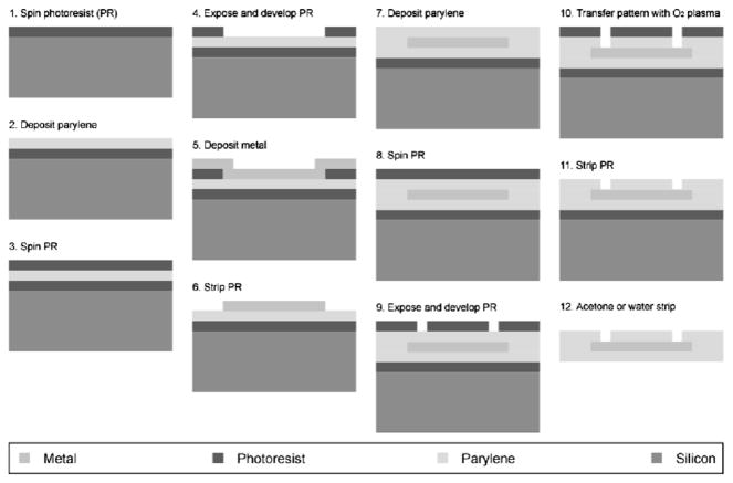
The electrode array is fabricated as described in [4], with a sandwich structure of parylene-metal-parylene. Parylene-C is a USP class VI biocompatible material, and its mechanical properties provide the necessary flexibility to make good epidural contact with the spinal cord. The microfabrication process is outlined in Fig. 1, and begins with an optional layer of sacrificial photoresist being spun onto a wafer followed by a deposition of 5 μm thick parylene-C. The metal layer, patterned using liftoff, was deposited using e-beam evaporation, and composed of a titanium adhesion layer of 100 Å followed by 2000 Å of platinum. The top layer of parylene-C is also 5 μm thick, and openings to expose the metal were achieved with oxygen plasma etching.
Figure 1.
Microfabrication process
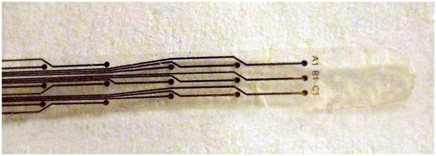
The completed devices were released from the wafer using acetone or water, and annealed in a vacuum oven at 200°C for 48 hours. A partial photograph of a typical device is shown in Fig. 2. The full microfabricated device is 59 mm × 3 mm, and has a 9×3 array of electrodes which are 250 μm in diameter with a parylene grid structure to help prevent delamination.
Figure 2.
Completed microelectrode array
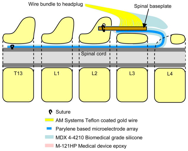
Due to the difficulty in preventing infection at connectors across the skin in chronic experiments, it is highly desirable for all signals to pass through a headplug on the rat, where the large bone surface, lack of muscle tissue, and minimal movement of skin make it an ideal location to minimize this risk. After preliminary experiments in a living animal proved that the mechanical strains imposed by its movement would make a reliable all-MEMS device that spans the headplug and spine unfeasible, a cable assembly was devised to confine strain on the array to acceptable limits. Fig. 3 illustrates how this assembly and the microfabricated array fit together and are placed along the spine of the animal after implantation. The assembly is composed of a spinal baseplate, a wire bundle, and a headplug with another set of wires to be implanted in the legs of the animal to record EMG signals. The baseplate is composed of a standard FR-4 PCB substrate, and has a bundle of 27 teflon coated, 75 μm gold wires soldered to it. These wires are connected to a custom headplug with high density connectors. Openings on the microfabricated array that expose the platinum are connected to the baseplate using silver epoxy. The entire assembly is coated with biomedical grade epoxy and silicone elastomer to insulate all electrical connections and provide mechanical strength while retaining the flexibility wherever necessary. A silicone cap is formed on the end of the baseplate to protect the array from external moving tissue, and a thin layer of silicone, roughly 100 μm thick, was also applied to the array to reduce stress concentration as it bends with the rat’s spine during movement. Thicker silicone on the array in earlier prototypes was found to be detrimental to the health of the spinal cord due to the pressure applied from a more rigid array, indicating that flexibility is an important design requirement for a successful spinal cord implant. The whole assembly process resulted in up to three of 27 electrodes being non-functional prior to surgery, which is acceptable for this experiment.
Figure 3.
Use of the implant including array and cable assembly along with its positioning on the spine. Vertebral segments are numbered, with the head of the rat towards the left.
EXPERIMENT
Surgical implantation of the implant involves first removing some bone and surrounding tissue from the L3 and L4 vertebrae. A suture is threaded through the spinal column and used to draw the array inside it, with positioning confirmed by opening small windows at other spinal segments. When the arrangement illustrated in Fig. 3 is achieved, the tip of the array is sutured to the dura of the spinal cord. The spinal baseplate has a forked shape that fits around the L2 spinous process, where it is sutured. The headplug is fixed to the skull of the rat using screws and dental cement (PMMA). Other than the headplug, the entire implant is contained within the rat, with the wire bundle being looped under the skin for stress relief. EMG wires are implanted in the legs, and a complete spinal cord transection is performed at segments T7–T9, resulting in hindlimb paralysis.
Six rats were given implants, with two being terminated early due to complications related to the surgery. After being given a week to heal, stimulation tests are conducted on a bi-weekly basis. Two modes of spinal cord stimulation are tested, with both using a pulse train from a voltage source, typically 40 Hz with 0.2 ms pulse width and 0–10V amplitude. Monopolar stimulation uses the body ground wire as the anode and a site on the microelectrode array as the cathode. Bipolar stimulation chooses both the cathode and anode from the microelectrode array. Three types of tests are performed: stimulation threshold testing, evoked response recording, and stepping. Threshold voltages are the miminum voltage necessary to evoke responses in hindlimb muscles, and are determined using monopolar stimulation at the beginning of each testing session. Evoked response involves stimulating the spinal cord at various voltages and reduced frequency (0.3 Hz) and recording the EMG responses in the hindlimbs. Stepping involves suspending the rat over a treadmill and stimulating electrodes to invoke stepping motions and also recording EMG responses. Full study of the biological implications of this test is the long term goal of this implant, but is a work in progress and beyond the scope of this paper.
RESULTS AND DISCUSSION
The primary goal of this device is to retain functionality through the course of the experiment and achieve the ability to induce stepping in spinalized rats.
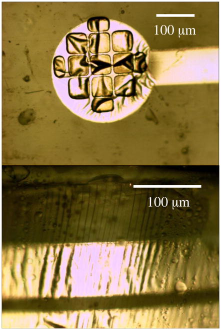
A sample set of threshold voltages is shown in Table 1. Typically, thresholds are 1–5V, with failed electrodes not showing any response at higher voltages. Variation in thresholds of working electrodes over time did not show consistent trends, suggesting that it was caused by minor changes in electrode positioning from one testing session to another rather than degradation of electrodes. Visual inspection of explanted devices supports this conjecture, as the electrode sites did not show delamination, but the arrays did reveal many stress lines in the parylene that passed through the platinum traces that connect electrode sites to the spinal baseplate. An example is shown in Fig. 4, which was photographed from the explant of rat #1 after six weeks. Although the baseplate was designed to minimize damaging movement, it could not eliminate it entirely. The working hypothesis for the failure of some electrodes with time is that these stress lines can break connectivity of the metal traces. One complication in examining explanted arrays is the difficulty in removing the tissue around the implant, which requires either a dissection procedure with a high likelihood of imparting mechanical stress or an acid treatment which appears to permeate the parylene and ripple the platinum surface, as seen in Fig. 4.
Table 1.
Sample threshold voltages in volts from a testing session. Non-functional stimulation sites are marked with a hyphen.
| Row | Column | ||
|---|---|---|---|
| Left | Centre | Right | |
| 1 | 4 | 2 | 2 |
| 2 | 2.5 | 3.5 | 2 |
| 3 | 4.5 | 2.5 | 2 |
| 4 | - | 4 | 2 |
| 5 | - | 6 | 3.5 |
| 6 | 1.5 | 1.5 | 2.5 |
| 7 | 2 | 2 | 3 |
| 8 | 2 | 1.5 | 4 |
| 9 | 2 | 2 | - |
Figure 4.
Photographs of the explanted device show the electrode remains intact, but stress lines are visible.
Table 2 illustrates the number of active electrodes for each of the four surviving rats. The spine of rat #1 provided some difficulty in correctly positioning the array during surgery, requiring insertion and removal several times. This may explain why its reliability was poorer than that of the others, as this could initiate mechanical damage. The other three implants had only a few electrodes fail after four weeks, which satisfies the initial reliability goal for this application. Rat #2 was kept alive longer to see how long the implant would survive, and after 8 weeks there remained only six non-functional electrodes, three of which were unconnected before surgery.
Table 2.
Number of failed electrodes with time
| Rat | Time of threshold test | ||
|---|---|---|---|
| Before surgery | 1 week after surgery | 4 weeks after surgery | |
| 1 | 2 | 9 | 11 |
| 2 | 3 | 3 | 6 |
| 3 | 2 | 3 | 4 |
| 4 | 2 | 3 | 3 |
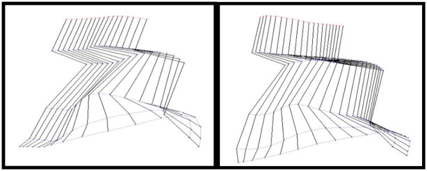
This reliability gives our implant design the ability to study stepping ability over time, just like wire based electrodes, but they have the added benefit of site selectivity afforded by a high density microfabricated array. Stepping was indeed achieved through stimulation of the spinal cord with the rat suspended over a treadmill. Fig. 5 illustrates the motion capture system used to record stepping ability and a stick diagram representing motion with no stimulation. As expected, the rat drags its feet due to the hindlimb paralysis. Fig. 6 shows the stick diagrams when the rat undergoes bipolar stimulated between two different electrode pairs. To our knowledge, this is the first stepping achieved by a spinalized rat stimulated by a MEMS electrode array. Of note is that the stimulation site pairs for the two different stepping patterns in Fig. 6 were close together on the array, suggesting that the high density electrode configuration of this device is of great value in understanding the biological mechanisms underlying locomotion and its application to recovery after spinal cord injury.
Figure 6.
Stepping motion with stimulation. The two stepping patterns were achieved by stimulating between different electrodes.
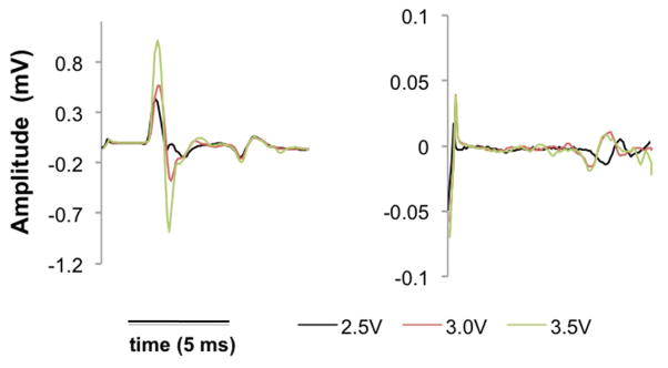
EMG recording is also very valuable in obtaining biological information. Fig. 6 shows two recordings, where we can identify monosynaptic responses, which generally occur in the first 6 milliseconds, and polysynaptic responses, which occur later. Of note is that the recording on the left shows both a monosynaptic and polysynaptic responses, while the right only shows the latter. Again, the high density of electrode sites proves to be valuable in eliciting different biological responses.
CONCLUSION
We have designed and fabricated a spinal cord implant for rats with a microelectrode array. The implant can survive in a living rat for over four weeks and possibly much longer, and though it shows signs of mechanical damage, the impact on functionality is minimal. Our implant can successfully provide a means for stimulating the spinal cord and recording evoked responses, and stimulation induces stepping in a rat with a completely transected spinal cord. The microelectrode array differentiates this device from past research and shows how the ability to better control the site of stimulation over wire based implants results in varied EMG responses and stepping patterns. Such information can open new doors in understanding the neurobiological circuits inside the spinal cord and possible treatments for locomotion recovery in victims of spinal cord injury.
Figure 7.
EMG response for two different stimulation pairs at three different voltages.
Acknowledgments
This research was funded by NIH BRP grant R01-EB0076151 and DoD TATRC grant W81XWH-09-2-0024. The authors would also like to thank Trevor Roper and all our colleagues at the Caltech Micromachining Lab and the Edgerton Lab at UCLA.
References
- 1.One Degree of Separation: Paralysis and Spinal Cord Injury in the United States. Christopher and Dana Reeve Foundation; 2009. [Google Scholar]
- 2.Ichiyama RM, Courtine G, Gerasimenko YP, Yang GJ, Brand R, Lavrov I, Zhong H, Roy R, Edgerton VR. Step Training Reinforces Specific Spinal Locomotor Circuitry in Adult Spinal Rats. 2008;29:7370–7375. doi: 10.1523/JNEUROSCI.1881-08.2008. [DOI] [PMC free article] [PubMed] [Google Scholar]
- 3.Ichiyama RM, Gerasimenko YP, Zhong H, Roy RR, Edgerton VR. Hindlimb stepping movements in complete spinal rats induced by epidural spinal cord stimulation. Neuroscience Letters. 2005;383(3):339–344. doi: 10.1016/j.neulet.2005.04.049. [DOI] [PubMed] [Google Scholar]
- 4.Rodger DC, Li W, Fong AJ, Ameri H, Meng E, Burdick JW, Roy RR, Reggie Edgerton V, Weiland JD, Humayun MS, Tai YC. Flexible microfabricated parylene multielectrode arrays for retinal stimulation and spinal cord field modulation. Proc. 4th International IEEE-EMBS Special Topic Conference on Microtechnologies in Medicine and Biology; Okinawa, Japan. 31–34, 2006. [Google Scholar]
- 5.Meacham KW, Giuly RJ, Guo L, Hochman S, DeWeerth SP. A lithographically-patterned, elastic multi-electrode array for surface stimulation of the spinal cord. Biomedical Microdevices. 2008;10(2):259–269. doi: 10.1007/s10544-007-9132-9. [DOI] [PMC free article] [PubMed] [Google Scholar]
- 6.Rodger DC, Li Wen, Ameri H, Ray A, Weiland JD, Humayun MS, Tai YC. Parylene-based Microelectrode Technology for Intraocular Retinal Prostheses. Proc. IEEE-NEMS 2006 Flexible; pp. 743–746. [Google Scholar]


