

Abstract
Hollow hard shell particles of 200 nm and 2 micron diameter with a 10 nm thick porous silica shell have been synthesized using polystyrene templates and a sol–gel process. The template ensures than the hollow particles are monodispersed, while the charged silica surface ensures that they remain suspended in solution for weeks. When filled with perfluorocarbon gas, the particles behave as an efficient contrast agent for colour Doppler ultrasound imaging in human breast tissue. The silica shell provides unique properties compared to conventional soft shell particles employed as ultrasound contrast agents: uniform size control, strong adsorption to tissue and cells immobilizing particles at the tissue injection site, a long imaging lifetime, and a silica surface that can be easily modified with biotargeting ligands or small molecules to adjust the surface charge and polarity.
Introduction
Ultrasound imaging is used frequently for medical diagnosis because it is safe, fast, and noninvasive. Ultrasound’s major shortcoming is its image contrast when compared to techniques such as magnetic resonance imaging (MRI). Therefore, methods to improve ultrasound image contrast and quality are crucial to its new applications. Microbubbles generated by agitating saline have been used as a contrast agent for ultrasound since the 1960’s. These are free bubbles and limited to right heart imaging, as they do not survive pulmonary capillary circulation. More stable microbubbles have been commercialized, three of which are currently FDA approved in the U.S. (Albunex®, Optison®, and Definity®).
The FDA approved ultrasound image contrast particles previously mentioned, are gas bubbles entrained within soft-shells made of proteins, such as albumin, or lipids. Soft shell ultrasonic contrast particles, specifically proteins, polysaccarides, and lipid based particles, have not been extended to sizes below 400 nm. This is due to the high surface tension of water, which prevents air filled nanobubbles from forming at atmospheric pressure for the time needed for imaging. The polymeric make up of a micro-bubble greatly influences its properties. For example microbubbles made of phosphlipids are considered soft-shell paticles and are much more sensitive to pressure changes. Microbubbles made of polycyanoacrylate are hard-shell and thus produce more robust and stable particles.1 Furthermore, polymeric microbubbles have been shown in animal studies to be a viable tool for renal imaging by way of intravenous injection.2 Ultrasound contrast particles have not been limited to polymeric materials, as many inorganic particles have also been shown to possess promising echogenic properties. Air filled porous silica coated gold, porous silica encapsulated ferrite, and porous borate and aluminate particles, which are considered hard shell particles have been shown to have favorable ultrasound enhancement capabilities.3–6 Uncalcined hollow silica-gel particles have been shown to behave as soft-shelled particles that also exhibit ultrasound contrast properties.7 The only nanoscale bubbles observed to date have been adsorbed on surfaces of single crystal silicon.8 To our knowledge, there are no rigid or hard shell hollow, inorganic hybrid particles being used as ultrasound contrast agents. Hollow silica shells can be synthesized with a large range of particle sizes down to 100 nm diameter.9,10 Besides access to smaller uniform sizes and low toxicity,11 there are other advantages of using nanoporous silica shells to contain a micro- or nanobubble (a) silica facilitates adhesion to tissue and cells thereby making the particles immobile; (b) silica can be doped to modify its strength, (c) nanoporous shells can be chemically modified with fluorophores, (d) the silica surface can also be covalently conjugated to cell receptor targeting agents or to small molecules in order to adjust the surface charge and polarity. In this report, the first three properties are exploited to demonstrate the potential utility of gas filled silica micro- and nanoshell particles for ultrasound-enhanced imaging.
Perfluorcarbon (PFC) vapour filled hollow silica nano- and microshells can be effectively utilized as immobile, rigid ultrasound image contrast particles (UICP) when injected subcutaneously. The reason that this platform could be advantageous over some commercially available UICPs is the highly adsorptive nature of silica gel. The immobility of the uncoated silica shells in tissue makes this platform amenable to be used as an adjunct or as a possible replacement to needle localization of nonpalpable tumors to mark them for surgical removal. For the past fifteen years, surgeons have removed early stage breast cancers by placing a wire in the breast tumor under X-ray or ultrasound guidance to mark the detected abnormality for removal by the surgeon. However, this procedure is associated with a 20–50% rate of positive margins necessitating a second operation. In the past few years, some surgeons have reduced the number of second surgeries needed in breast conservation therapy by injecting radioactive seeds under image guidance in and around the tumor preoperatively to better localize the entire tumor to achieve negative surgical margins.12–15 The disadvantages of using radioactive seeds include: (a) the half-life of the seed being only a few hours, thereby requiring the seeds to be implanted on the day of surgery, (b) difficulty marking multiple tumor foci or fields of cancer cells, which is common in ductal in situ carcinoma (DCIS), (c) exposure of the patient and surgeon to ionizing radiation (d) the need for trained radiation personnel, (e) the need for a large bore needle to inject the seed which is painful for the patient, (f) the lack of 3D imaging tools for radioactive seeds in the operating room, and (g) the seeds are expensive to purchase and dispose safely.
The use of ultrasound for the location and removal of tumors has already been shown to be a useful intraoperative technique; however, the limited imaging contrast of tumors reduces the effectiveness of this method. In this report, the gas filled silica micro and nanoshells injected directly in tissue are shown to persist for several days and can be readily imaged in human breast tissue in three dimensions after injection.
Results and discussion
Synthesis
Initial attempts to synthesize 2.0 micron (μm) hollow silica particles were done using the same sol gel procedure as the one used to produce hollow silica nanoshells.16 This procedure utilizes a polystyrene bead as a template that is coated with a polyamine to facilitate the sol gel reaction (shown in Fig. 1).
Fig. 1.
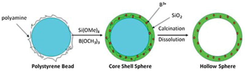
A general scheme for the sol–gel synthesis of hollow shells.
Once the sol gel reaction is completed, the organic core is calcined to give a hollow particle.17,18 When extended to the microscale, this process yielded hollow microshells that were very fragile. These particles would fracture and eventually break completely after 1–2 h of bath sonication or centrifugation above 1.7 RCF (Fig. 2).
Fig. 2.
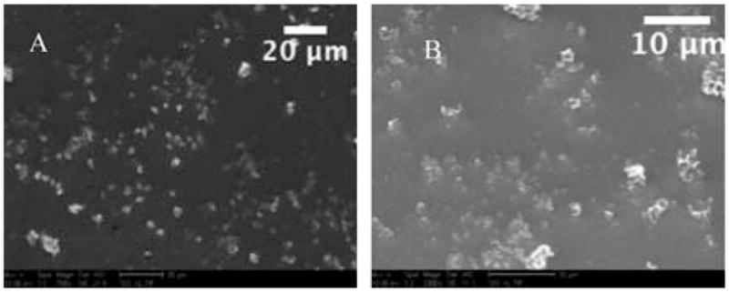
Two SEM images of material recovered after calcination using the standard procedure for particle synthesis, without boron doping. As seen above A (758× mag.) and B (2300× mag.) there are very few well-formed, unbroken particles produced using the standard procedure.
In order to prepare a more robust microshell, another component needed to be incorporated into the silica matrix to strengthen it; therefore, boron was doped into the silica matrix during the sol–gel reaction by addition of trimethoxyboron. Due to the difference in reactivity of tetramethylorthosilicate and trimethoxyboron, the former reagent was allowed to react for 2 h before addition of trimethoxyboron. This allowed the slower reacting silane to begin the template formation of the silica microshell, before allowing the boron to be incorporated into the nascent silica matrix. The particles were washed with water and ethanol to remove unreacted starting materials. The 2 μM polystyrene bead core was subsequently removed by calcination at 550 °C for 18 h. This yielded a hollow porous silica gel particle with a relatively uniform wall thickness, approximately 10 nm, and possessing greater structural strength compared to the corresponding hollow silica particles. The boron-doped microshells can withstand 12 h of bath sonication with little to no visible breakage; although only 10 min of sonication is required for complete dispersal of the 2 μM boron-doped silica shells in aqueous solutions. These sonicated 2 μm silica shells remain dispersed in solution for at least several days, requiring only minor agitation to regain suspension weeks later. Scanning electron microscopy (SEM) showed (Fig. 3) well-formed monodisperse spheres and the measured zeta potential (ZP) was −39 mV (see supplemental information). The 200 nm silica shells were synthesized using a similar technique; however, boron doping is not required since the smaller nanoshells are sufficiently robust to withstand ultrasound dispersal. The increased strength of the nanoshells may be attributed to the similar wall thickness found in both the small and large shells. The 200 nm silica shells can withstand 24 h of bath sonication with little to no visible breakage; however, only 60 min of sonication is required for complete dispersal of the 200 nm silica shells, as shown by dynamic light scattering. The sonicated 200 nm silica shells remain dispersed in solution for at least several weeks. Scanning electron microscopy (SEM) showed well formed, monodisperse spheres and a measured zeta potential of −32 mV confirmed sufficient surface charge for a stable dispersion. The particles were filled with per-fluropentane (PFP) in order to test whether the particles could effectively contain perflurocarbon (PFC) vapors for a significant period of time. PFP was used because of its insolubility in water. The difference in index of refraction between PFP vapour and that of the aqueous surroundings made it an excellent candidate for the gaseous portion of an UICP. Vapour-filling was accomplished by first evacuating the hollow particles (~10−3 torr) for approximately 30 min. Using a gas syringe, the PFP vapours in the headspace above the liquid PFP were injected into the vessel containing the particles. This was repeated three times, followed by the addition of degassed water to trap the PFP vapors inside the nano and microshells. The gas filled nano and microshells were sonicated just enough to create a uniform suspension: approximately 30 s for 2 μm and 200 nm shells. To confirm that the particles contained PFP, the silica shells were visualized using a standard light microscope approximately 1 h after filling with gas (Fig. 4). The difference in the indices of refraction between liquid media and gas caused the particles to appear brighter than the background, as seen in the brightfield microscope images. The gas-filled particles are easily identifiable, whereas the solvent filled particles are difficult to locate.
Fig. 3.

Three SEM images are of the boron-doped 2 μm shells with increasing magnification (9342×, 9354×, and 18 708×). Microshells are well formed and virtually no broken shells are observed.
Fig. 4.
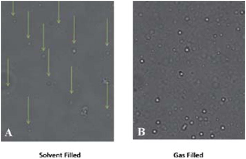
Light microscope images of 2 μM silica shells at 40× magnification. (A) Solvent filled microshells are difficult to visualize, while (B) PFC vapour filled microshells appear bright in the image.
Ultrasound imaging
In order to determine if the vapour-filled particles would produce an ultrasound signal, the vapour-filled particles were injected into agar. The mode that was most responsive was colour Doppler imaging (CDI). In CDI, colour is assigned to pixels when echoes returning from a voxel are non-correlated following the transmission of multiple ultrasound pulses. Gas bubbles can generate a CDI signal either by moving or if the first pulse of a multi-pulse sequence destroys the bubble that has been termed “stimulated acoustic emission.”19–21 These differences can be measured directly or as a phase shift from which the Doppler frequency is obtained.22,23 For 100 μL of a 2 mg/ml suspension injected into an agar phantom, the CDI signal persisted for 75 min of continuous imaging. This means in a clinical setting the particle could be imaged multiple times since the ultrasound is only applied periodically. Conversely, conventional ultrasound microbubble imaging agents which use soft shells, such as albumin or lecithin, have only been shown to persist for 15 min in tissues.
To determine whether the vapour remained in the 2.0 μm particles or dissolved into fat tissue, the particles were injected into chicken livers and imaged every 24 h. As shown in Fig. 5, there was a strong signal post injection and after 24 h. The imaging time used for each observation was approximately 5 min. The relative area of observable signal of the 72 h study implies a half-life of approximately 24 h (Fig. 5). The signal begins to degrade after 48 h and is barely distinguishable after 72 h. After 24 h, there is some degradation of the CDI in both nano and microshells, but this could be due to migration of the injected sample within the excised tissue or the diffusion of PFP from the microbubble core (ultrasound instrument details and parameters are provided in supplemental information).
Fig. 5.

CDI sonograms of 100 μg of PFC-filled microshells injected in a tissue phantom imaged at 24 h (A) 24 h, (B), 48 h, and (C) 72 h. The signal decreases over time, but is still easily visible after 48 h. (D) CDI observable signal vs. imaging delay time. A fit of the data shows that the microshells have a half-life ~24 h.
The weight factor equation (eq 1, see ESI†) allows for estimation of the number of particles for a given mass of silica shells, thereby providing an estimate of the total gas payload for a specific mass of nano or micro shells. The 2 μm and 200 nm nanoshells differ in internal volume by 1000×, but as shown in Table 1 they differ in mass by only 100×. Consequently, the microshells have 37 times more gas storage for a similar mass injection. However, the CDI signal observed is only twice as large for the microshells when compared to the nanoshells. A summary of injection volumes, number of particles and corresponding masses can be seen in Table 1.
Table 1.
Particle summary
| 200 nm Silica Particles | 2.0μM Silica Particles | |
|---|---|---|
| Internal Volume (One particle) | 0.028 μm3 | 28.74 μm3 |
| 50 μL Injection | ||
| Number of particles | 1.1 × 10¹⁰ | 3.95 × 10⁸ |
| Mass | 100 μg | 100 μg |
| Area of CDI signal | 23.7 mm2 | 47.1 mm2 |
| 100 μL Injection | ||
| Number of particles | 2.2 × 10¹⁰ | 7.9 × 10⁸ |
| Mass | 200 μg | 200 μg |
| Area of CDI signal | 43.4 mm2 | 95.5 mm2 |
To determine if the particles would perform similarly in human tissue, breast tissue from a prophylactic mastectomy was tested. In order to have a proper histological analysis of the tissue, India ink was also added to the particle suspension to locate and track the injection.
As seen in Fig. 6, the vapour filled particles can be identified just as well in the breast tissue as in the chicken liver tissue using CDI ultrasound. For the 100 μL injection of both the nano- and micro-gas-filled shells, there is a clear CDI signal. Although the nanoshell injection contained 100 times more particles than that of the microshells, the microshells show a CDI observable signal that is 2.3 times larger based on the area of observable signal. This could be a result of several factors: first, while there are 100 times more nanoshells (for a 100 μg injection), each micro-shell has a gas volume 1000 times greater. For equal mass injections this translates to 37 times greater payload of gas for a 100μg injection of microshells. Second, due to the microshells larger size and payload, it is probable that a more favourable interaction with the sound wave occurs with microshells, thereby producing a larger observable signal. Even on a weight basis, the nanoshells are less efficient contrast agents than the microshells. They are, however, more efficient on a volume basis; this is unexpected since bubbles which are smaller than a micron cannot normally exist due to their instability and would be expected to have a weak interaction with ultrasound radiation.
Fig. 6.

CDI images of 100 μL of PFC filled nano and microshells in human masectomy tissue: (a) after injection of 4 × 10¹⁰ nanoshells. (b) After injection 8 × 10⁸ microshells The nanoshells image (A) is magnified ~2.5× and thus in this comparison appears to be larger. An accurate measure the DCI area can be found in Table 1.
Fluorescence microscopy was performed on breast tissue in order to determine if the microshells remained at the injection site after ultrasound imaging (Fig. 7). The injection solution used consisted of PFP gas filled, Alexafluor-488 covalently linked microshells, along with 10 μL/ml India ink. The resulting solution was injected into excised prophylactic mastectomy breast tissue. After the tissue was imaged by ultrasound, a small piece of the breast tissue was resected and placed into a histology cassette for tissue fixation. ‡ Images were taken of different areas where India ink was visible under brightfield conditions, fluorescent examination confirmed the presence of the microshells at the injection site. The microshells presence provided further evidence that the CDI signal did originate from the PFC 2μm fluorescently labelled microshells.
Fig. 7.

Optical imaging of 100 μL of microshells injected into mastectomy tissue, (A) brightfield image of embedded breast tissue. Black regions on image are traces of India ink, (40× Mag). (B) Green fluorescent image of 2 μm microshells in embedded breast tissue. (C) Zoom in region of green fluorescent image using Image J. White circles identify regions where 2 μm microshells can be observed. Scale upper right is 2 μm.
Conclusions
A new hybrid inorganic rigid platform for an ultrasound image contrast particle has been successfully synthesized and tested. Gas filled hollow porous silica microshells possess properties that cannot be duplicated by soft shell counterparts (a) synthesis of a wide range of specific sizes, (b) covalent functionalization of the shell surface, (c) long term suspension in solution, (d) adhesion to cells and tissue, and (e) long imaging lifetime in tissue. The PFP vapour filled micro- and nanoshells are a promising complement to the other ultrasound contrast agents currently being used. They also represent a promising replacement to the radioactive seeds currently employed to improve breast tumor localization for several reasons: (a) they have a longer lifetime than that of the several minute lifetime of commercially available UICPs, (b) several foci can be marked using very fine gauge needles, (c) they can be imaged in 3D, and (d) no specialized radiation safety is required. There is little risk to the patient due to the small injected dose needed, known nominal cellular toxicity of silica, and their removal during surgery. The ability to make bubbles that can be imaged in the nanometre size regime also raises the possibility of new applications, such as imaging microcapilliaries in tumors and sentinel lymph nodes near tumors.
Supplementary Material
Acknowledgments
Authors would like to thank the NIH-Nano tumor grant 5U54CA 119335-04 for financial support and Larrisa Low for her help with the breast tissue samples in the operating room. We acknowledge the in vivo Cancer and Molecular Imaging Center (NCI-P50-CA128346) for partial salary support for Yuko Kono and Robert Mattrey.
Footnotes
Electronic Supplementary Information (ESI) available: Further characterisation data. See DOI: 10.1039/c0md00139b/
The paraffin embedded tissue block was sliced until India ink was visible and sectioned in 5 micron slices, with two consecutive slices per slide, and spaced at 100 microns before the next slide. Slides were removed of paraffin by soaking for 30 mins in xylene and sealed with Cytoseal for visualization. The paraffin embedded tissue slides were analyzed using a Nikon Eclipse E600 upright fluorescent microscope fitted with a 40× objective (Nikon Plan Apo, 0.95NA) and with a triple bandpass filter (DAPI/FITC/Texas Red w/Single-Band Exciters, Chroma Technology Corp). Areas of interest were first identified by the location of India ink with bright field imaging; afterwards, a fluorescent image was captured using a Spot camera. The images were processed for background level and mean fluorescent signals using ImageJ software (National Institutes of Health).
Contributor Information
Sarah L. Blair, Email: slblair@ucsd.edu.
Jessica Wang-Rodriguez, Email: jwrodriguez@ucsd.edu.
Robert F. Mattrey, Email: rmattrey@ucsd.edu.
William C. Trogler, Email: wtrogler@ucsd.edu.
Notes and references
- 1.Kiessling F, Huppert J, Palmowski M. Curr Med Chem. 2009;16:627–642. doi: 10.2174/092986709787458470. [DOI] [PubMed] [Google Scholar]
- 2.Zhanwen X, et al. Nanotechnology. 2010;21:145607. doi: 10.1088/0957-4484/21/14/145607. [DOI] [PubMed] [Google Scholar]
- 3.Glajch JL, Carpenter AP, Jr, Cheesman EH. 2001:38. [Google Scholar]
- 4.Glajch JL, Loomis GL, Mahler W. 1992:10. [Google Scholar]
- 5.Chen Y-S, Kruizinga P, Joshi PP, Kim S, Homan K, Sokolov K, Frey W, Emelianov S, Oraevsky AA, Wang LV. Proc SPIE. 2010;7564:75641Q/75641–75641Q/75648. [Google Scholar]
- 6.Zhang M, Kitamoto Y, Abe M. J Phys IV. 1997;7:C1/669–C661/670. [Google Scholar]
- 7.Lin PL, Eckersley RJ, Hall EAH. Adv Mater. 2009;21:3949–3952. [Google Scholar]
- 8.Main ML, Goldman JH, Grayburn PA. J Am Coll Cardiol. 2007;50:2434–2437. doi: 10.1016/j.jacc.2007.11.006. [DOI] [PubMed] [Google Scholar]
- 9.Kirkhorn J, Frinking Peter JA. Ultrasonics Symposium, 1999. Proceedings. 1999 IEEE. 1999. Nico de Jon and Hans Torp; pp. 0_2–0_22. [Google Scholar]
- 10.Nico de Jong AB, Frinking Peter. Echocardiography 2013 Jnl Cardiovascular Ultrasound & Allied Techniques. 2002;19:229–240. [Google Scholar]
- 11.Brunner TJ, Wick P, Manser P, Spohn P, Grass RN, Limbach LK, Bruinink A, Stark WJ. Environ Sci Technol. 2006;40:4374–4381. doi: 10.1021/es052069i. [DOI] [PubMed] [Google Scholar]
- 12.Cox C, Furman B, Stowell N, Ebert M, Clark J, Dupont E, Shons A, Berman C, Beauchamp J, Gardner M, Hersch M, Venugopal P, Szabunio M, Cressman J, Diaz N, Vrcel V, Fairclough R. Ann Surg Oncol. 2003;10:1039–1047. doi: 10.1245/aso.2003.03.050. [DOI] [PubMed] [Google Scholar]
- 13.Gray R, Salud C, Nguyen K, Dauway E, Friedland J, Berman C, Peltz E, Whitehead G, Cox C. Ann Surg Oncol. 2001;8:711–715. doi: 10.1007/s10434-001-0711-3. [DOI] [PubMed] [Google Scholar]
- 14.Richard JG, Barbara AP, Patricia JK, Michael CR. Am J Surg. 2004;188:377–380. [Google Scholar]
- 15.Blair SL, Thompson K, Rococco J, Malcarne V, Beitsch PD, Ollila DW. J Am Coll Surg. 2009;209:608–613. doi: 10.1016/j.jamcollsurg.2009.07.026. [DOI] [PubMed] [Google Scholar]
- 16.Yang J, Lind JU, Trogler WC. Chem Mater. 2008;20:2875–2877. [Google Scholar]
- 17.Ding X, Yu K, Jiang Y, Hari B, Zhang H, Wang Z. Mater Lett. 2004;58:3618–3621. [Google Scholar]
- 18.Wu W, Caruntu D, Martin A, Yu MH, O’Connor CJ, Zhou WL, Chen JF. J Magn Magn Mater. 2007;311:578–582. [Google Scholar]
- 19.Tiemann K, Becker H, Bimmel D, Schlief R, Nanda NC. Echocardiography. 1997;14:65–69. doi: 10.1111/j.1540-8175.1997.tb00692.x. [DOI] [PubMed] [Google Scholar]
- 20.Blomley MJK, Albrecht T, Cosgrove DO, Patel N, Jayaram V, Butler-Barnes J, Eckersley RJ, Bauer A, Schlief R. Radiology. 1999;210:409–416. doi: 10.1148/radiology.210.2.r99fe47409. [DOI] [PubMed] [Google Scholar]
- 21.Hadinoto K, Cheow WS. Drug Dev Ind Pharm. 2009;35:1167–1179. doi: 10.1080/03639040902824845. [DOI] [PubMed] [Google Scholar]
- 22.Schwartz RLPaRA. Practical Doppler ultrasound for the clinician. Urban & Schwarzenberg; Baltimore: 1991. [Google Scholar]
- 23.Woodcock PAaJP. Doppler ultrasound and its use in clinical measurement. Academic Press; New York: 1982. [Google Scholar]
Associated Data
This section collects any data citations, data availability statements, or supplementary materials included in this article.