Abstract
Both accuracy and efficiency are critical for the implementation of biomechanical model-based deformable registration into clinical practice. The focus of this investigation is to evaluate the potential of improving the efficiency of the deformable image registration of the human lungs without loss of accuracy. Three dimensional finite element models have been developed using image data of fourteen lung cancer patients. Each model consists of two lungs, tumor, and external body. Sliding of the lungs inside the chest cavity is modeled using a frictionless surface based contact model. The effect of type of element, finite deformation and elasticity on the accuracy and computing time are investigated. Linear and quadrilateral tetrahedral elements are used with linear and nonlinear geometric analysis. Two types of material properties are applied namely: elastic and hyperelastic. The accuracy of each of the four models is examined using a number of anatomical landmarks representing the vessels bifurcation points distributed across the lungs. The registration error is not significantly affected by element type or linearity of analysis with an average vector error of around 2.8 mm. The displacement differences between linear and nonlinear analysis methods are calculated for all lungs nodes and a maximum value of 3.6 mm is found in one of the nodes near the entrance of the bronchial tree into the lungs. The 95 percentile of displacement difference ranges between 0.4 and 0.8 mm. However, the time required for the analysis is reduced from 95 min in the quadratic elements nonlinear geometry model to 3.4 min in the linear element linear geometry model. Therefore using linear tetrahedral elements with linear elastic materials and linear geometry is preferable for modeling the breathing motion of lungs for image guided radiotherapy applications.
1. Introduction
1.1 General
Radiotherapy is a widely used method for cancer treatment. The quality of the treatment is measured by its accuracy to treat the target while sparing the surrounding healthy tissues. Radiotherapy has advanced with the introduction of image guided radiotherapy (IGRT), where alignment of the patient is performed at each treatment session. This process requires image registration to relate the current treatment image to the diagnostic quality planning images. Rigid image registration is typically used in the process. However, most organs experience different sources of deformation (Langen and Jones 2001). As an example, lungs are subjected to deformation caused by breathing, gravity, and acceleration body force (Lambert and Wilson 1973). Therefore, deformable image registration is required to ensure a high level of accuracy. Biomechanical based computational modeling has the potential to improve diagnostics, treatment, planning and interventions (Holzapfel 2004) while offering a practical solution to the complexity of material, geometry and structure of biological tissues (Humphery 2003). Finite element modeling is a popular method used in the field (Carter et al 2005). It was described as the most suitable procedure to solve the complex elasticity problem of the lungs (Lee and Frankus 1975). Its potential stems from the unique features that encompass the realistic physical material properties of tissues, geometry, and applied loads. Since biomechanical modeling of lungs was introduced by Mead et al 1970, finite element modeling has been widely used to study the lungs (Matthews and West 1972, Sundaram and Feng 1977, Villard et al 2005, Zhang et al 2004, Brock et al 2005, Al-Mayah et al 2008, Werner et al 2009).
Although a detailed model with a number of modeling features can provide an accurate representation of the soft tissue, it imposes a practical restriction of its clinical applications as longer computing time is required to reach the solution. These features include nonlinear geometry (finite deformation), nonlinear material properties (finite elasticity), nonlinear boundary condition (contact models), and heterogeneity.
1.2.Nonlinear material properties
Describing the mechanical properties of soft tissues, Humphrey 2003 concluded Roy 1880 findings that “most soft tissues exhibit a nonlinear, inelastic, heterogeneous, anisotropic character that varies from point to point, from time to time and from individual to individual.” Soft tissues possess mechanical characteristics which are similar to that of rubber material as a result of the long-chain, and cross linked polymer existing in both materials. Therefore, the typical stress strain relationship of soft tissues under loading is nonlinear under large strains which requires the application of finite elasticity. Details and reviews of the theory can be found in Holzapfel 2000, Martins et al 2006, and Boyce and Arruda 2000. However, the simplicity of linear elasticity has led to its popularity in the area of modeling of soft tissues. This raises the question of the importance of including the nonlinearity in modeling lungs under breathing motion, especially as the suitability of the theory depends on the applied strain and not only on the intrinsic tissue behavior. Chabanas et al 2004 stated that under low strains the performance of the linear and nonlinear material properties is the same. Wittek et al 2009 concluded that the simple constitutive material model is sufficient for modeling the brain deformation instead of the previously used hyperviscoelastic model.
1.3. Nonlinear geometry analysis
On the other hand, the large deformation experienced by most human organs, including the lungs, may require nonlinear geometry (finite deformation) analysis as opposed to the linear geometry (infinite deformation) required for small deformation. In infinitesimal deformation analysis, the displacement of the current position at a specific time from the initial position is assumed to be smaller in comparison with the dimensions of the body. Hence geometrical changes are ignored and a linear relationship between the reference and deformed geometry can be applied. However, in large deformation problems, the kinematic (the study of motion and deformation without reference to the cause) relationships become nonlinear and elements are distorted from their original shapes to the point that these elements become unsuitable for the analysis. Therefore, the deformation between the initial configuration at the beginning of the loading step and the deformed configuration at the end of the step cannot be ignored as in the case of linear geometry analysis. This feature is normally included in modeling a number of anatomical sights including brain (Miller et al 2010), breast (Samani et al 2001), and lungs (Al-Mayah et al 2008).
1.4. Nonlinear boundary conditions
Most organs are sliding relative to each other creating a third source of nonlinearity related to boundary conditions. In fact, sliding is an important feature for organs’ physiological performance in order to perform normally and without any distortion or abrasion on the surface (D'Angelo et al 2004, Loring et al 2005, Widmaier et al 2006). The effect of boundary conditions on the accuracy of the finite element modeling of soft tissues is more pronounced than the material properties (Miller et al 2010, Tanner et al 2006). Sliding has proved to be important for the accuracy of the deformable image registration of the lungs (Al-Mayah et al 2008), hence it is included in all models investigated in this study.
1.5. Heterogeneity
Heterogeneity is a scale dependent assumption. For example, the analysis of lungs on the scale of alveolus requires a heterogeneous model, however, a homogeneous model is sufficient for a larger scale analysis (Lia-Fook 1981). This was demonstrated by the experimental investigation conducted by Tai and Lee 1981, where the inclusion of the bronchial tree in the lung samples did not affect the mean deformation of the sample. Similar conclusions can be drawn from (Lia-Fook and Kallok 1982) where the deformation of adjoining bronchial and arterial tubes is limited to the adjacent space. A detailed biomechanical modeling of lungs and bronchial tree developed by the authors reached similar conclusion where 96% of the nodes are within 2.5 mm displacement differences resulting in an average dose difference of 0.35 Gy between models (Al-Mayah et al. 2010).
Furthermore, the irregular geometry of the lungs requires a smaller number of elements that encompass the entire volume in order to obtain a smooth surface. Tetrahedral elements offer a good choice over hexahedral elements to achieve this requirement (Carter et al 2005). However, linear tetrahedral elements are sensitive to locking and may not be suitable to model soft tissues. Therefore, higher order elements such as quadratic tetrahedral may become necessary to overcome this challenge. However, longer computation time is expected as the size of the model increases.
This study concentrates on the significance of type of elements, assumption of deformation (finite or infinite) and material properties on the modeling of lung motion between inhale and exhale phases. The speed of the analysis and the accuracy of the registration will be measured.
2. Method and Materials
2.1.General
Image data of fourteen non-small cell lung cancer patients with different tumor sizes and locations were acquired at inhale and exhale positions using 4DCT (time+3D) with a voxel size of 0.98 × 0.98 × 2.5 mm3. Patients’ data include tumor location, tumor size, diaphragm movement, and volume difference (and percentage) between inhale and exhale, as listed in Table 1. Diaphragm movement and volume difference are of a particular interest since they provide an indication of the type of applied deformation upon which the finite and infinite deformation assumption will be decided.
Table 1.
Patient information including tumor location and volume, diaphragm movement in the superior-inferior (SI) direction, and volume change between inhale and exhale
| Patient | Tumor Location | Tumor Size | Diaphragm Mov. | Vol. change |
|---|---|---|---|---|
| (cm3) | (cm) | (vol%) cm3 | ||
| P1 | LLL | 2.63 | 1.25 | 202 (6%) |
| P2 | RML | 21.51 | 1.25 | 190 (5%) |
| P3 | LLL | 1.57 | 1.25 | 306 (8%) |
| P4 | RML | 4.14 | 1.00 | 267 (6%) |
| P5 | RLL | 4.63 | 0.75 | 289 (13%) |
| P6 | RUL | 0.67 | 1.25 | 396 (11(%) |
| P7 | LUL | 0.08 | 0.25 | 50 (1%) |
| P8 | RUL | 2.83 | 1.00 | 230 (10%) |
| P9 | RUL | 59.33 | 2.00 | 442 (9%) |
| P10 | LLL | 25.24 | 1.25 | 357 (5%) |
| P11 | LUL | 20.5 | 0.5 | 207 (6%) |
| P12 | Mediastinum | 78.03 | 0.5 | 336 (7%) |
| P13 | LLL | 5.3 | 0.5 | 276 (9%) |
| P14 | LUL | 0.76 | 0.75 | 168 (7%) |
LUL=left upper lobe, LLL=Left lower lobe, RUL=right upper lobe, RML=right middle lobe, RLL=right lower lobe
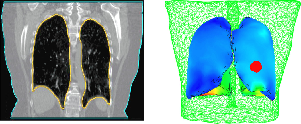
Three dimensional finite element models have been developed. Each model consists of both lungs, tumor, and body, as shown in Figure 1. The primary model is based on the contoured lungs, tumor, and body of the inhale images. Both lungs and body are also contoured on the exhale images. These surfaces are used to find boundary conditions on the external body and lungs represented by the displacement difference of the node locations between the two breathing phases. Four-node linear and ten-node quadratic tetrahedral elements are investigated. The average volume of the elements used in the lungs and tumor model is 0.17 cm3. However, smaller elements are required in some regions with complex geometry features to cover the entire volume.
Figure 1.
Patient specific finite element model based on the CT image data. Each model consists of both lungs, and the tumor (in red) surrounded by the external body (in green).
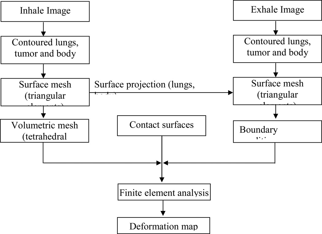
The details of the model’s development processes are illustrated in Figure 2. After contouring the lungs, tumor and body in both inhale and exhale images, a surface mesh of each of the components is created using a finite element preprocessor (HyperMesh, Altair Engineering, Troy, MI). Using the surface mesh, a volumetric mesh is created for the inhale breathing phase which is considered the primary representation of the model. The surface meshes of the exhale lungs are used to find the location difference between inhale and exhale positions and these differences are applied as displacement boundary conditions. Contact surfaces are applied to the surface of the lungs allowing sliding between them and the corresponding chest cavity. A finite element package (ABAQUS, v 6.8, Providence, RI) is used for the analysis. Further details of the finite element model development can be found in Brock et al 2005.
Figure 2.
Finite element model development procedures of human lungs.
For each type of element, nonlinear (NLG) and linear geometry (LG) analyses are applied representing the finite and infinite deformation assumptions respectively, as illustrated in Table 2. In the nonlinear geometry, hyperelastic material properties are applied based on the experimental data reported by Zeng et al 1987 using the following relationship (Al-Mayah et al 2008b):
where c, a1, a2, and a4 are experimental-based constants with mean values of 11.8 g/cm, 0.43, 0.56 and 0.32, respectively, ρoW is the strain energy/volume, and εi are strain components in a x, y, or z direction.
Table 2.
Study matrix
| Element Type | Analysis | Material | Boundary |
|---|---|---|---|
| Linear Tetrahedral | Linear geometry (LG) | Linear elastic | Contact surface |
| Nonlinear geometry (NLG) | Hyperelastic | Contact surface | |
| Quadratic Tetrahedral | Linear geometry (LG) | Linear elastic | Contact surface |
| Nonlinear geometry (NLG) | Hyperelastic | Contact surface |
In the linear geometry analysis, elastic material properties of the lungs are used with a modulus of elasticity of 3.74 kPa representing the slope of the linear portion of the nonlinear stress-strain relationship (Al-Mayah et al 2008). In both linear and nonlinear elastic models Poisson’s ratio of 0.4 is applied based on the findings of a previous study conducted by the authors (Al-Mayah et al 2009). In all models, elastic material properties are applied for the external body with modulus of elasticity and Poisson’s ratio of 6 kPa, and 0.4, respectively.
2.2. Boundary conditions and contact surfaces
The boundary conditions are applied at the inhale representation of the external body and the chest cavity surfaces in contact with lungs. Using the exhale images as the final position of the deformation, the difference in location between the inhale and exhale position of the surface nodes of the body and the chest cavities are calculated and applied as displacement boundary conditions. A surface projection program (HyperMorph, Altair) is used for the process.
Surface-to-surface contact models are applied on the lung-chest cavity interfaces in order to simulate the sliding of the lungs during breathing. Frictionless contact surfaces are used to simulate the lubrication effect of the pleural liquid on the surface of the lungs. This value of friction is proved to be realistic as it results in a minimum registration error (Al-Mayah et al 2009).
2.3. Accuracy test
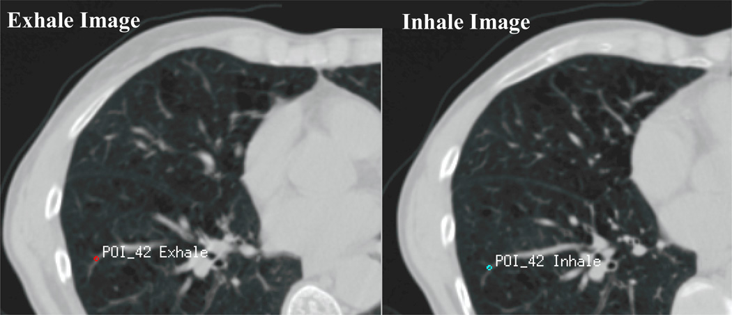
An average of 48 bifurcation points per patient are used to evaluate the accuracy of the model. These points represent anatomical landmarks of the vessel bifurcations distributed in both lungs, as shown in Figure 3. Their positions are identified in the inhale image of the lungs. The corresponding anatomical points are then identified in the exhale images. The difference between the position of the point on the inhale and exhale image represents the image-based displacement of the points. The displacement of the points is then calculated using the finite element model to obtain the model-based displacement. The difference between the image-based and model-based displacement is the registration error.
Figure 3.
The difference in location between the inhale and exhale bifurcation point represents the image-based displacement which is compared to the displacement of the same point calculated from the finite element model. The difference between the image-based and model-based displacement is the registration error.
3. Results
3.1. Model accuracy
Using bifurcation points, the accuracy of image registration are evaluated using the 4 modeling themes, as reported for each type of element. The average absolute error and the standard deviation are reported in the left right (LR), anterior-posterior (AP), and superior-inferior (SI) directions in addition to the vector values, as listed in Table 3. It is interesting to note that there is no significant difference between the four models and the error in the three directions is less than the radiation dose gird size of 2.5 mm. It is worth mentioning that the results are within the range of the accuracy of different deformable image registration techniques reported by a multi-institution deformable registration study where the average vector magnitude is ranging between 1.0 and 3.0 mm (Brock 2010).
Table 3.
Average absolute bifurcation error in LR, AP, SI, and vector values (Dimensions in mm).
| Average absolute error (mm) ± SD |
||||
|---|---|---|---|---|
| Linear Tetrahedral | Quadratic Tetrahedral | |||
| LGEOM | NLGEOM | LGEOM | NLGEOM | |
| LR Direction | 0.91 (± 0.76) | 0.94 (± 0.78) | 0.91 (± 0.74) | 0.94 (± 0.77) |
| AP Direction | 1.34 (± 1.14) | 1.34 (± 1.14) | 1.35 (± 1.13) | 1.36 (± 1.15) |
| SI Direction | 1.89 (± 1.64) | 1.84 (± 1.65) | 1.88 (± 1.64) | 1.85 (± 1.69) |
| Vector | 2.81 (± 1.71) | 2.82 (± 1.73) | 2.83 (± 1.72) | 2.83 (± 1.81) |
Although a considerable effort was made to ensure a uniform distribution of the bifurcation points around the lungs, a perfectly representative distribution of the bifurcation points is hard to achieve. Therefore, all nodes of the lungs are used to calculate the displacement differences between linear geometry and nonlinear geometry models for each type of element. The absolute maximum, the average 95 percentile, and the average differences in the LR, AP, and SI directions are reported in Table 4. The 95 percentile shows a value of less than 1mm difference in all directions. In addition, a small average difference of displacement of all nodes of 0.1 mm is found. However, the absolute maximum difference is 2.4 mm in the AP direction in the case of the linear tetrahedral elements and 3.6 mm in the case of quadratic tetrahedral elements. The location of the maximum difference is at the entrance of the bronchial tree into the lungs. Since this location is expected to experience little deformation during breathing, the error is not associated with the value of deformation that necessitates the use of nonlinear geometric analysis. Since the surface nodes are near the applied boundary conditions and these boundary conditions are the same in all four model types in each patient, the calculation of the displacement difference of all nodes may be affected by the surface nodes. Therefore, the surfaces nodes are removed and the displacement differences of the internal nodes are calculated. As illustrated in Table 4, removing the surface nodes has insignificant effect on the calculated differences. This is mainly attributed to the fact that the boundary condition displacement is not applied directly to the external lungs’ nodes but through the contact pressure that is calculated using the contact models. In other words, the contact models allow the lungs to slide inside the chest cavities.
Table 4.
Displacement difference between linear and nonlinear geometry models of all nodes with linear and quadratic tetrahedral elements.
| Displacement difference between NLGEOM and LGEOM (mm) |
||||||
|---|---|---|---|---|---|---|
| Linear Tetrahedral | Quadratic Tetrahedral | |||||
| LR | AP | SI | LR | AP | SI | |
| All Nodes | ||||||
| Absolute Max Difference | 1.9 | 2.4 | 2.2 | 3.1 | 3.6 | 3.0 |
| 95 Percentile | 0.5 | 0.7 | 0.4 | 0.5 | 0.8 | 0.5 |
| Average Difference | 0.0 | 0.1 | −0.1 | 0.0 | 0.1 | −0.1 |
| Internal Nodes Only | ||||||
| Absolute Max Difference | 1.2 | 1.6 | 1.4 | 3.1 | 3.4 | 2.9 |
| 95 Percentile | 0.3 | 0.6 | 0.3 | 0.5 | 0.8 | 0.5 |
| Average Difference | 0.0 | 0.1 | −0.1 | 0.0 | 0.1 | −0.1 |
In addition to the need for accuracy, there is also a need for practical considerations when implementing a finite element model-based algorithm into a radiotherapy application. The average computation time required for running the model is 3.4, 7.7, 19.7, and 95 minutes for linear elements with linear and nonlinear geometry, and quadratic tetrahedral elements with linear and nonlinear geometry, respectively. The percentage of computation time relative to the quadratic elements and nonlinear geometry are listed in Table 5. As expected, the fastest process is the case of linear geometry model and linear tetrahedral elements with an average of 3.4 min. The longest running time is the case of nonlinear geometry analysis and quadratic tetrahedral elements with an average of 95 min. It is worth mentioning that the computational time is measured only when the solution converges. If the solution does not converge with nonlinear geometry and quadratic tetrahedral elements the program is stopped and the quality of the mesh is improved. The same model is used for rest of the analysis to ensure consistency among the models for comparison of the results.
Table 5.
The percentage of the computation time relative to nonlinear geometry model with quadratic tetrahedral elements
| Computation time relative to NLGEOM of quadratic tetrahedral % |
||||
|---|---|---|---|---|
| Patient | Linear Tetrahedral | Quadratic Tetrahedral | ||
| LGEOM | NLGEOM | LGEOM | NLGEOM | |
| P1 | 4 | 8 | 17 | 100 |
| P2 | 9 | 22 | 52 | — |
| P3 | 4 | 6 | 19 | — |
| P4 | 3 | 4 | 22 | — |
| P5 | 4 | 11 | 13 | — |
| P6 | 2 | 3 | 11 | — |
| P7 | 21 | 30 | 87 | — |
| P8 | 3 | 4 | 11 | — |
| P9 | 9 | 60 | 61 | — |
| P10 | 2 | 3 | 14 | — |
| P11 | 4 | 10 | 31 | — |
| P12 | 5 | 12 | 30 | — |
| P13 | 4 | 6 | 26 | — |
| P14 | 3 | 5 | 17 | — |
| Average | 6 | 13 | 29 | |
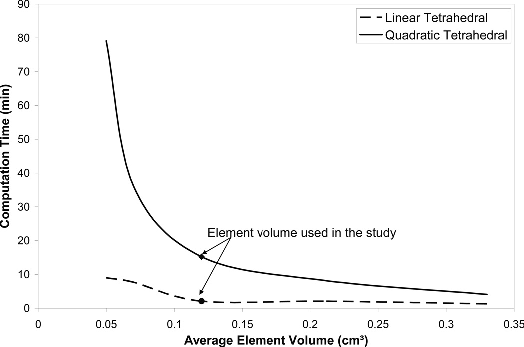
In order to find the effect of element size on the accuracy and the running time, the patient with the largest breathing motion (P9) is selected for the investigation, as listed in Table 1. Six element volumes are investigated with an average volume ranging between 0.33 to 0.05 cm3 for both linear and quadratic tetrahedral elements. The average vector value of the error using 71 bifurcation points is found to be 2.8 (±1.8) mm. The element volume is shown to have no effect on the accuracy of the model. However the computation time increases from 1.3 to 9 min using linear elements, and from 4.1 to 79.1 min using quadratic elements, as shown in Figure 4. This is in an agreement with previous study on 21 prostate cancer patients where the accuracy of the location of implanted markers was not affected by the size of the elements (Brock et al 2008).
Figure 4.
Element volume effect on computation time in the patient (P9) that experiences the largest breathing motion.
4. Discussions and conclusion
In order to use the finite element modeling for deformable image registration an efficient and accurate model is required. Efficiency of the modeling requires a fast and easy-to-use model. Unlike hexahedral elements, linear tetrahedral elements are widely used in a number of commercially available meshing softwares. This is an essential step for integrating modeling procedures with medical applications. However, their accuracy is challenged by the locking properties of the linear tetrahedral elements when modeling the nearly incompressible materials of the soft tissues. Therefore, a comparison between nonlinear tetrahedral elements is conducted in the registration of human lungs with cancer. A previous study by Carter et al 2005a on using quadratic and linear tetrahedral elements for breast models for surgical application using the MR image data of two volunteers has shown little difference between the models of two types of elements regardless of the compressibility of the material. Although lungs experience different deformation and have different material properties and geometry from the breast, the current study reaches the same conclusions. This may be attributed to the fact that deformation of the lungs due to breathing motion is small thus linear tetrahedral elements are sufficient.
The deformation pattern of the lungs between inhale and exhale breathing phases can provide better understanding of the significance of material and geometric nonlinearity considerations. Lung deformation is considered as nonhomogeneous and can be analyzed using finite or infinite elasticity (Lai-Fook 1981). Different approaches have been adopted in describing lung deformation. Matthews and West 1972 assumed a large deformation that requires a nonlinear stress strain law. Another approach assumed resistance of the inflated lungs to the deformations that change the shape (Wilson 1983). This deformation can be divided into a uniform and a superimposed nonuniform deformation (Lambert and Wilson 1973). However, it is considered to be an infinite elasticity problem when the nonuniform deformation is small. This small deformation assumption was also reflected in the linear geometry approach adopted by Lee et al 1976.
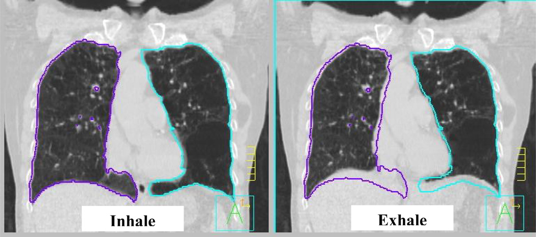
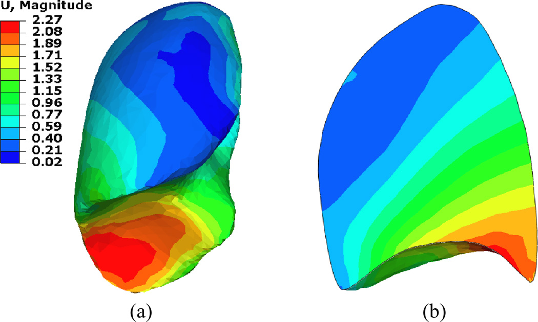
The deformation distribution inside the lung has been well addressed by investigating the lung’s tumor motion during the breathing cycle. In a comprehensive study on 152 lung cancer patients, Liu et al 2007 has shown that the tumor motion is associated with the tumor location, where the higher motion occurs at the lower lobes of the lungs and is highly correlated with the diaphragm motion. In addition, this motion is mainly in the SI direction. This is also shown in the current study as illustrated in Figure 5. However the relationship between the tumor motion and its location in the SI direction is not linear since most of the motion is absorbed in the lower lobes. This is as a result of the “sponginess” of the tissues (Liu et al 2007). Similar behavior is observed in this study as demonstrated in Figure 6. The deformation map (vector values in cm) of patient P9 is shown since it experiences the largest diaphragm motion of 2.0 cm. Most of the deformation is concentrated in the lower lobes of the lungs and it is absorbed quickly within a small distance from the diaphragm-lung interface. This is also indicated by a relatively small percentage of volume change (average of 7.4%) between the inhale and exhale phases of the lungs. Therefore, it is expected that even if a large deformation is applied to the lung, most of the lung will experience little deformation leading to the fact that linear geometry and linear material properties can provide accurate results similar to the nonlinear geometry and material properties regardless of the type of elements.
Figure 5.
Breathing motion of the lungs represented by the difference of lung position between inhale and exhale positions. Most of the deformation occurs in the lower portion of the lobes in the SI direction. No significant deformation is observed in the upper portion of the lungs.
Figure 6.
Deformation distribution (a) in the right lung and (b) its cross section in the region of the largest deformation.
Furthermore, the constitutive modeling of soft tissues has little effect on the accuracy of deformable image registration (Carter et al 2005) which helps to overcome the material variability of soft tissue between different locations in one organ and between individuals (Miller et al 2010). Wittek et al 2009 emphasized this fact by comparing the accuracy of viscohyperelastic material properties of the brain to a simple linear elastic model and finding no significant changes between the two. A similar conclusion can be drawn from the current study where the constitutive model has little effect on the deformation. However, as the current study is conducted with the sliding model of the lungs, it was observed in a previous study that the material properties of the lungs do have an effect on the accuracy of the model when no contact surface is applied (Al-Mayah et al 2008).
The importance of the boundary conditions and the contact surface sliding of the lungs have been reported in a number of studies including the brain (Miller et al 2010), breast (Tanner et al 2006), and lungs (Al-Mayah et al 2008). In addition, the sliding is an important feature for normal function of the lungs (D'Angelo et al 2004, Loring et al 2005, Widmaier et al 2006). Therefore, the boundary nonlinearity (contact surface) is applied in the four modeling themes adopted in this study. An interesting observation confirmed that the using of contact does not affect the speed of the analysis.
Although the breathing motion of the lungs considered in this study is within the range of 9.1±2.4 mm reported by Balter et al 1998, the results should be considered with caution when the lungs experience larger deformation as in the case of image guided surgery or deep breathing scenario due to the difference in the magnitude of deformation experienced by the lungs.
Acknowledgements
The authors would like to thank Dr. Andrea Bezjak, the Addie MacNaughton Chair in Thoracic Radiation Oncology for her assistance in obtaining the patients data. This work was supported by the NIH 1R01CA124714-01A2.
References
- Al-Mayah A, Moseley J, Velec M, Brock K. Deformable registration of heterogeneous human lung incorporating the bronchial tree. Med Phys. 2010;37:4560–4571. doi: 10.1118/1.3471020. [DOI] [PMC free article] [PubMed] [Google Scholar]
- Al-Mayah A, Moseley J, Velec M, Brock K. Sliding characteristic and material compressibility of human lung: Parametric and Verification. Med. Phys. 2009;36:4265–4633. doi: 10.1118/1.3218761. [DOI] [PMC free article] [PubMed] [Google Scholar]
- Al-Mayah A, Moseley J, Brock KK. Contact surface and material nonlinearity modeling of human lungs. Phys. Med. Biol. 2008;53:305–317. doi: 10.1088/0031-9155/53/1/022. [DOI] [PubMed] [Google Scholar]
- Al-Mayah A, Moseley J, Velec M, Brock K. Effect of friction and material compressibility on deformable modeling of human lung. International Symposium on Computational Models for Biomedical Simulation - ISBMS ’08; July 7–8, 2008; London, UK. Heidelberg, Germany: Springer-Verlag; 2008b. pp. 98–106. LNCS 5104, Lecture Notes in Computer Science. [Google Scholar]
- Balter JM, Lam KL, McGinn CJ, et al. Improvement of CT-based treatment-planning models of abdominal targets using static exhale imaging. Int. J. Radiat. Oncol. Biol. Phys. 1998;41:939–943. doi: 10.1016/s0360-3016(98)00130-8. [DOI] [PubMed] [Google Scholar]
- Boyce MC, Arruda EM. Constitutive Models of Rubber Elasticity: A Review. Rubber Chem. Technol. 2000;73:504–523. [Google Scholar]
- Brock KK, Sharpe MB, Dawson LA, Kim SM, Jaffray DA. Accuracy of finite element model-based multi-organ deformable image registration. Med. Phys. 2005;32:1647–1659. doi: 10.1118/1.1915012. [DOI] [PubMed] [Google Scholar]
- Brock KK, Nichol AM, Ménard C, et al. Accuracy and sensitivity of finite element model-based deformable registration of the prostate. Med. Phys. 2008;35:4019–4025. doi: 10.1118/1.2965263. [DOI] [PubMed] [Google Scholar]
- Brock KK Deformable Registration Accuracy Consortium. Results of a multi-institution deformable registration accuracy study (MIDRAS) Int J Radiat Oncol Biol Phys. 2010;76:583–596. doi: 10.1016/j.ijrobp.2009.06.031. [DOI] [PubMed] [Google Scholar]
- Carter TJ, Sermesant M, Cash DM, Barratt DC, Tanner C, Hawkes DJ. Application of soft tissue modelling to image-guided surgery. Med. Eng. Phys. 2005;27:893–909. doi: 10.1016/j.medengphy.2005.10.005. [DOI] [PubMed] [Google Scholar]
- Carter TJ, Tanner C, Hawkes DJ. A comparison of linear and quadratic tetrahedral finite elements for image-guided surgery applications. MIAS-IRC; November 29th–30th; Chancellors, Manchester, UK. 2005a. on line Proceedings, Paper 29. [Google Scholar]
- Chabanas M, Payan Y, Marécaux C, Swider P, Boutault F. Comparison of linear and non-linear soft tissue models with post-operative CT scan in maxillofacial surgery Medical Simulation. Lecture Notes in Computer Science. 2004;3078:19–27. [Google Scholar]
- D'Angelo E, Loring SH, Gioia ME, Pecchiari M, Moscheni C. Friction and lubrication of pleural tissues. Respiratory Physiol. Neurobiol. 2004;142:55–68. doi: 10.1016/j.resp.2004.05.006. [DOI] [PubMed] [Google Scholar]
- Holzapfel GA. Nonlinear Solid Mechanics: A Continuum Approach for Engineering. Chichester; New York: Wiley; 2000. [Google Scholar]
- Holzapfel GA. Solids and structures. vol. 2. Chichester: Wiley; 2004. Computational biomechanics of soft biological tissue. Encyclopedia of computational mechanics, chapter 18; pp. 605–635. [Google Scholar]
- Humphrey JD. Continuum biomechanics of soft biological tissues. Proc R Soc Lond A. 2003;459:3–46. [Google Scholar]
- Langen KM, Jones DTL. Organ motion and its management. Int. J. Radiat. Oncol. Biol. Phys. 2001;50:265–278. doi: 10.1016/s0360-3016(01)01453-5. [DOI] [PubMed] [Google Scholar]
- Lai-Fook SJ. Elasticity analysis of lung deformation. Annals of Biomedical Engineering. 1981;9:451–462. doi: 10.1007/BF02364763. [DOI] [PubMed] [Google Scholar]
- Lai-Fook SJ, Kallok MJ. Bronchial-arterial interdependence in isolated dog lung. J. Appl. Physiol.: Respirat. Environ. Exercise Physiol. 1982;52:1000–1007. doi: 10.1152/jappl.1982.52.4.1000. [DOI] [PubMed] [Google Scholar]
- Lee GC, Frankus A, Chen PD. Small distortion properties of lung parenchyma as a compressible continuum. J. Biomech. 1976;9:641–648. doi: 10.1016/0021-9290(76)90106-8. [DOI] [PubMed] [Google Scholar]
- Lee GC, Frankus A. Elasticity properties of lung parenchyma derived from experimental distortion data. Biophys. J. 1975;15:481–493. doi: 10.1016/S0006-3495(75)85832-2. [DOI] [PMC free article] [PubMed] [Google Scholar]
- Liu HH, Balter P, Tutt T, et al. Assessing respiration-induced tumor motion and internal target volume using four-dimensional computed tomography for radiotherapy of lung cancer. Int. J. Radiat. Oncol. Biol. Phys. 2007;68:531–540. doi: 10.1016/j.ijrobp.2006.12.066. [DOI] [PubMed] [Google Scholar]
- Loring SE, Brown RE, Gouldstone A, Butler JP. Lubrication regimes in mesothelial sliding. J. Biomech. 2005;38:2390–2396. doi: 10.1016/j.jbiomech.2004.10.012. [DOI] [PubMed] [Google Scholar]
- Martins PALS, Natal Jorge RM, Ferreira AJM. A Comparative Study of Several Material Models for Prediction of Hyperelastic Properties: Application to Silicone-Rubber and Soft Tissues. Strain. 2006;42:135–147. [Google Scholar]
- Matthews FL, West JB. Finite element displacement analysis of a lung. J. Biomech. 1972;5:591–600. doi: 10.1016/0021-9290(72)90031-0. [DOI] [PubMed] [Google Scholar]
- Mead J, Takishima T, Leith D. Stress distribution in lungs: a model of pulmonary elasticity. J. Appl. Physiology. 1970;28:596–608. doi: 10.1152/jappl.1970.28.5.596. [DOI] [PubMed] [Google Scholar]
- Miller K, Wittek A, Joldes G, et al. Int. J. Numer. Meth. Biomed. Engng. Vol. 26. 2010. Modelling brain deformations for computer-integrated neurosurgery; pp. 117–138. [Google Scholar]
- Roy CS. The elastic properties of the arterial wall. Phil. Trans. R. Soc. Lond. B. 1880;99:1–31. [Google Scholar]
- Samani A, Bishop J, Plewes DB. Biomechanical 3-D finite element modeling of the human breast using MRI data. IEEE Trans. Med. Imaging. 2001;20:271–279. doi: 10.1109/42.921476. [DOI] [PubMed] [Google Scholar]
- Sundaram SH, Feng CC. Finite element analysis of the human thorax. J. Biomech. 1977;10:505–516. doi: 10.1016/0021-9290(77)90104-x. [DOI] [PubMed] [Google Scholar]
- Tai RC, Lee GC. Isotropy and homogeneity of lung tissue deformation. J. Biomech. 1981;14:243–252. doi: 10.1016/0021-9290(81)90069-5. [DOI] [PubMed] [Google Scholar]
- Tanner C, Schnabel JA, Hill DLG, Hawkes DJ, Leach MO, Hose DR. Factors influencing the accuracy of biomechanical breast models. Med. Phys. 2006;33:1758–1769. doi: 10.1118/1.2198315. [DOI] [PubMed] [Google Scholar]
- Villard P-F, Beuve M, Shariat B, Baudet V, Jaillet F. Simulation of lung behaviour with finite elements: Influence of bio-mechanical parameters. Proc. 3rd Int. Conf. on Medical Information Visualisation-BioMedical Visualisation MediVis V. 2005:9–14. [Google Scholar]
- Werner R, Ehrhardt J, Schmidt R, Handels H. Patient-specific finite element modeling of respiratory lung motion using 4D CT image data. Med Phys. 2009;36:1500–1511. doi: 10.1118/1.3101820. [DOI] [PubMed] [Google Scholar]
- Widmaier EP, Raff H, Strang KT. Vander's human physiology: the mechanisms of human body function. 10th edn. New York: McGraw-Hill; 2006. [Google Scholar]
- Wilson TA. Nonuniform lung deformations. J. Appl. Physiol.: Respirat. Environ. Exercise Physiol. 1983;54:1443–1450. doi: 10.1152/jappl.1983.54.6.1443. [DOI] [PubMed] [Google Scholar]
- Wittek A, Hawkins T, Miller K. On the unimportance of constitutive models in computing brain deformation for image-guided surgery. Biomech Model Mechanobiol. 2009;8:77–84. doi: 10.1007/s10237-008-0118-1. [DOI] [PMC free article] [PubMed] [Google Scholar]
- Zeng YJ, Yager D, Fung YC. Measurement of the mechanical properties of the human lung tissue. J. Biomech. Eng. 1987;109:169–174. doi: 10.1115/1.3138661. [DOI] [PubMed] [Google Scholar]
- Zhang T, Orton NP, Mackie TR, Paliwal BR. Technical note: A novel boundary condition using contact elements for finite element based deformable image registration. Med. Phys. 2004;31:2412–2415. doi: 10.1118/1.1774131. [DOI] [PubMed] [Google Scholar]


