Abstract
We have developed an integrated strain array for cell culture enabling high-throughput mechano-transduction studies. Biocompatible cell culture chambers were integrated with an acrylic pneumatic compartment and microprocessor-based control system. Each element of the array consists of a deformable membrane supported by a cylindrical pillar within a well. For user-prescribed waveforms, the annular region of the deformable membrane is pulled into the well around the pillar under vacuum, causing the pillar-supported region with cultured cells to be stretched biaxially. The optically clear device and pillar-based mechanism of operation enables imaging on standard laboratory microscopes. Straightforward fabrication utilizes off-the-shelf components, soft lithography techniques in polydimethylsiloxane, and laser ablation of acrylic sheets. Proof of compatibility with basic biological assays and standard imaging equipment were accomplished by straining C2C12 skeletal myoblast cells on the device for 6 hours. At higher strains, cells and actin stress fibers realign with a circumferential preference.
Keywords: High-throughput, mechanical strain, cell mechanotransduction, fluorescence microscopy
1. Introduction
In vivo, cells undergo deformation and stress in normal physiology. Skin cells, for example, resist high mechanical stress, and simple monolayers of epithelia and endothelia are regularly subjected to bending and shear forces. Muscle cells are also subjected to high strains as the heart pumps, lungs expand, and biceps flex. To study these processes in vitro, commercially available systems like a Flexcell™ can apply both tensile and compressive strains to large cell populations [1] and numerous custom systems have been reported [2–11]. Using these systems, applied strain fields have been applied on a variety of biological models, including muscle, stem, bone and endothelial cells. Tensile strain has been shown to affect cell alignment, morphology, differentiation, proliferation, apoptosis and signaling [2, 12–16].
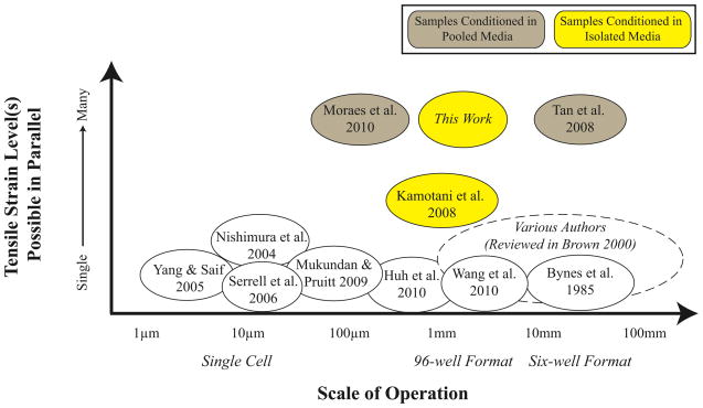
However, most systems apply a single strain profile across an entire plate or population; thus many of these prior studies were limited to few, significantly different strain levels, disallowing comparisons across experiments. Inconsistencies in the strain fields of commercial devices have also been implicated in contradictory results [17, 18]. As a result, some groups have turned to microfluidics and soft lithography to apply strain to small populations of cells [5, 7], including innovative geometries to create controlled variations in strain [6] or porous substrates for biomimetic functions [15]. Other approaches have used microscale devices to mechanically strain a single cell at a time [4, 8]. While these silicon-based devices are easily and reliably calibrated, the manipulation of cells and devices by hand is time consuming and low throughput. To create a high throughput system, Moraes et al. pressurizes and lifts an array of cylindrical posts to biaxially stretch polymer membranes. The posts rise to different heights, though, and place samples at different focal planes, complicating imaging while stretching [10]. Wang et al. created a device that addresses the focal plane issue but is limited to one strain level [19]. Further, multi-strain devices often circulate or pool media among samples experiencing different strain levels; such pooling couples the cell populations through paracrine signaling pathways and eliminates the possibility to investigate secreted factors and small molecule signaling under strain (Figure 1).
Figure 1.
Many devices have been designed and fabricated to apply tensile strain to cultured adherent cells. Most of these devices are designed to apply a single strain magnitude, negating high-throughput studies. For those devices designed to have multiple strain levels, media is pooled among the various strain levels, negating certain assays and complicating data with paracrine signaling.
We previously reported an early version of our Integrated Strain Array (ISA) which overcomes many of these obstacles [20]; here we detail an integrated system including: the pneumatic sensing and actuation systems, the microcontroller module, device fabrication, experimental validation, and an improved finite element model. Additionally, we present calibration data after standard autoclave sterilization treatment and demonstrate realignment of cells in the presence of cyclic strain.
2. Design and Fabrication
2.1 Design of the Integrated Strain Array
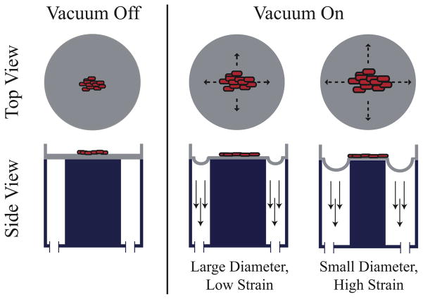
To address some of the issues with existing high-throughput solutions, we have designed and tested an Integrated Strain Array (ISA) for applying variable strain magnitudes to small cell populations. Our device utilizes the Society for Biomolecular Sciences (SBS) standard spacing for 96-well plates and is compatible with standard plate cell-culture techniques and inverted microscopy. As depicted in Figure 2, a polymer membrane at the base of each well is pulled down over a post to stretch cells adhered on the membrane top surface. Our 25-well design is fabricated on a 4″ wafer and configured to generate five replicates of five different strain magnitudes. The design is scalable if larger substrates are used for fabrication, and any combination of strain magnitudes and replicates is possible in SBS 96-well format. With the ISA, adherent cells stay in the same focal plane during stimulation for compatibility with automated imaging tools, plate readers and existing handling technology. We have connected wells with microfluidics for perfusion in some preliminary experiments with our devices where we pool media only from each column of wells at the same strain (this design not shown). Importantly, in the open well design, samples experiencing different strain magnitudes are isolated in separate wells to eliminate undesirable signaling effects.
Figure 2.
A thin biocompatible polymer is stretched under vacuum (denoted by downward arrows) over an acrylic post, creating a consistent strain field across each post and thus stretching the attached biological sample. In this configuration, the biological sample stays in the same focal plane with only small variations due to incompressibility effects.
We have focused our demonstration on typical, open-well plate culture operations rather than microfluidic media exchange for ease of calibration and uniform cell loading. With the open-well ISA, a variety of methods can be utilized for biophysiological assays using standard micropipette transfer techniques. Cells are imaged in situ, media can be collected and analyzed for soluble factors, cells can be enzymatically released from the wells and collected, or fixed and immunostained in situ.
The ISA is composed of two separate chambers: the pneumatic chamber and the cell culture chamber (Figure 3). A closed-loop control system modulates a laboratory vacuum supply (capable of applying up to 160 torr or 90 kPa pressure difference measured across the membrane) to provide a cyclic pressure waveform to the pneumatic chamber; the user defines the waveform magnitude and frequency. This cyclic pressure difference acts across a 150 μm polydimethylsiloxane (PDMS) membrane. PDMS also forms the walls of the cell culture chamber. The vacuum acts on the outer annular portion of the membrane in each individual well, pulling it down into the open cavity around each post (Figure 2). The central region of the membrane is correspondingly stretched over the post. The geometry of the post determines the strain field in the central region of each well; an array of post sizes yields an array of strain levels for a single device pressure. For these studies, we employ a biaxial strain field in 25 wells by using circular posts of five sizes. Post dimensions are varied by columns with five replicates each of 2 mm, 1.75 mm, 1.5 mm, and 1 mm radius posts and one solid row experiences no strain (control).
Figure 3.

Cartoon (left) and photographs of PDMS cell culture chamber (center) and acrylic pneumatic chamber (right). Wells match SBS spacing and volume for a 96-well plate; the wells have a 3 mm radius.
2.2 Fabrication of the Integrated Strain Array
Straightforward fabrication of the ISA combines: laser etching of polymethylmethacrylate (PMMA) for pneumatic chambers; soft lithography microfabrication techniques of PDMS for the cell culture chambers; and electronic and pneumatic hardware integration.
2.2.1 Pneumatic Chamber Fabrication
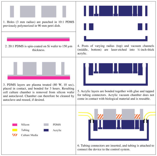
The pneumatic chamber is comprised of three layers of PMMA acrylic (Acrylite, Tap Plastic, Mountain View, CA), which are laser-cut on a LaserCam (Universal Laser Systems, Scottsdale, AZ) and assembled with acrylic cement (Tap Plastic) (Figure 5). The top layer includes the array of posts and tapped holes for tubing connectors (Quick-turn-tube fitting, McMaster-Carr, Santa Fe Springs, CA). The lower layers pattern the plenum, which distributes the source vacuum under every well in the array. Connected tubing is then attached to the control system (Figure 4).
Figure 5.
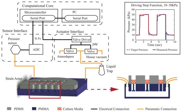
The pneumatic control system is connected to the acrylic pneumatic chamber. The flexible PDMS membrane layer of the cell culture chamber is stretched in proportion to the post size and cyclic pressure profile.
Figure 4.
Representative side view of fabrication of ISA. Cell culture chamber is formed out of bonded layers of PDMS and placed on top of bonded layers of laser-etched acrylic for normal operation.
2.2.2. Cell Culture Chamber Fabrication
The cell culture chamber is made of two layers of PDMS (Sylgard 182 and 184, Dow Corning, Midland, MI). For each layer, base and curing agent are mixed and defoamed in a planetary centrifugal mixer (AR-100, ThinkyUSA, Laguna Hills, CA). For the well layer, PDMS (Sylgard 184, 40 g of 10:1 base to curing agent weight ratio) is poured into a 90 mm petri dish and cured for 4 hours at 65 °C. We then punch 6 mm holes in the resulting 6 mm thick PDMS layer with a biopsy punch (Acuderm Inc, Ft. Lauderdale, FL) through a template for a SBS 96-well pattern. For the membrane layer, we spin coated 10 g of 20:1 PDMS (Sylgard 182) on a silicon wafer at 300 RPM for 30 seconds and 350 RPM for 60 seconds and cured this membrane for 4 hours at 65 °C to achieve a target thickness of 150 μm. The well layer and membrane wafer are then plasma treated at 80 W for 10 seconds (O2 Barrel Asher, Branson IPC/Novellus, San Jose, CA). The membrane layer and well layer are then placed in contact with light pressure by hand and left to bond for at least 3 hours before handling.
2.2.3 Device Assembly and Lubrication
The high degree of friction between the PDMS membrane and acrylic post requires lubricant to operate effectively. Industrial silicone-based lubricants were found to react with the membrane within 2–3 hours. This reaction created a very tacky surface that resisted applied strain and substantially degraded device performance. Water-based personal lubricants proved to substantially reduce friction and sustain their performance over the duration of our experiments (up to 6 hours) when maintained in a humidified environment. Lubricant (ID Glide, Westridge Laboratories Inc., Santa Ana, CA) was applied to the top of each acrylic post individually using a toothpick, and the culture chamber was aligned by hand and placed on top of the acrylic chamber.
2.2.4 Integration with Pneumatic Control System
We have designed and built a user-friendly and inexpensive pneumatic control system comprised of off-the-shelf components. The unit is divided into three major subsystems: a sensing module, a computational core, and an actuator module (Figure 5). The sensing module monitors the actual pressure reached in the pneumatic chamber below the membrane (ASDX015 analog sensor, Invensys Sensor Systems, Milpitas, CA). One port of the gauge pressure sensor is connected to the pneumatic chamber through abrasion-resistant polyurethane tubing and barbed reduction coupling connections (McMaster-Carr, Santa Fe Springs, CA) while the other port is exposed to atmospheric pressure. Pressure measurement data collected by the sensing module are sent to the analog-to-digital conversion input of microcontroller (Atmega 328RISC in a Dev09217 Arduino board, SparkFun Electronics, Boulder, CO) in the computational core.
The computational core also includes a graphical user interface (coded in C Sharp, Microsoft) that displays observed pressure from the sensing interface and outputs the desired magnitude, frequency, waveform, and proportional-integral-derivative control parameters to the actuator interface. To control the duty-cycle of two proportional valves (DS2833-927, Burkert, Irvine, CA), the microcontroller defines the pulse width modulation signal which is amplified by field-effect transistor switches (NTE 2390, NTE Electronics, Bloomfield, NJ). One valve is connected to the vacuum source and the other vented to atmosphere. We compared the performance of our pneumatic control system with a commercially available Flexcell™ control unit (Flexcell 5000 Tension, Hillsborough, NC) in tracking the target pressure for both sine and step functions between 10–50 kPa pressure difference across the membrane. Our system exhibits smaller step sizes, faster rise times, and less overshoot (data not shown).
3. Methods
3.1 Finite Element Model (FEM)
To model the device, we use a mesh of SHELL181 tetrahedral elements in ANSYS™ with 4 nodes. This element is capable of large deformations based on the Mindlin-Reissner shell theory where element kinematics allow finite membrane stretching. Two contact and target surfaces constitute a contact pair, CONTAC174 and TARGE170. The contact surface (PDMS membrane) is a deformable body while the target surface (PMMA post) is rigid body. In this model, we define the friction coefficient as an input parameter. Since the friction in our dynamic system is difficult to estimate, we examine the friction parameter effect on expected performance in a sensitivity analysis (table 1). This sensitivity analysis allows us to examine expected performance given manufacturing variability. The PDMS membrane was considered isotropic with Poisson’s ratio of 0.49 based on related literature [21–23]. The boundary elements of the culture chamber were constrained in displacement but not rotation. The normal penalty stiffness and penetration tolerance factor were set to 0.9 and 0.1, respectively. For the sensitivity analysis, we ran the finite element model with different input parameters to capture uncertainties resulting from variations in the manufacturing process and estimation of the friction coefficient (table 1). For example, the laser cam path for a 1 mm radius post yields radii up to 15% smaller due to the spot size of the laser. In the future, utilizing cutter compensation could generate more accurate target geometries.
Table 1.
Sensitivity Analysis. Input parameters for our finite element model were varied across a realistic range to understand the effects of variations in fabrication and assembly. Variations in membrane thickness, outer radius of 1 mm nominal radius post, and friction coefficient were determined empirically. Variations in elastic modulus are taken from the literature [23, 21, 22].
| Input Parameters
|
||||
|---|---|---|---|---|
| Membrane Thickness (μm) | Elastic Modulus of PDMS (MPa) | Outer Radius Post (mm) | Friction Coefficient | |
| Minimum Value | 130 | 0.5 | 1.7 | 0.01 |
| Target/Norminal Value | 150 | 0.75 | 2.0 | 0.035 |
| Maximum Value | 190 | 1.2 | 1.9 | 0.1 |
3.2 Calibration
To empirically validate the intra-well strain for each post radius, we physically calibrated the ISA using a patterned membrane. Five devices were assessed to determine the consistency of strain magnitude within a given well (intrawell), the repeatability across the device (interwell), and the manufacturing repeatability from device to device. Calibration devices are manufactured in the same manner as the standard cell culture chamber, with the added feature of 10 μm diameter, 10 μm high posts patterned 100 μm apart onto the membrane surface (figure S4). To take measurements, we applied a pressure step function to the ISA and imaged the patterned grid at 10X magnification (DMIRB inverted microscope, Leica Microsystems, Bannockburn, IL with Orca R2, Hamamatsu, Hamamatsu City, Japan) (figure 6). The device was placed in an incubator and cycled at a magnitude of 10 kPa pressure difference across membrane and 1 Hz frequency between imaging time points. Images were imported into MATLAB, and coordinates for a 4-by-4 grid of posts were selected manually from frame to frame. We calculated the Lagrangian strain tensor for each set of displacement vectors defined by the grid (9 elements total).
Figure 6.
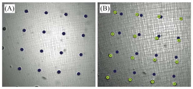
Representative image pair of calibration membrane on a 1 mm radius post at (A) 0 kPa and (B) 10 kPa applied pressure difference across the membrane. The coordinates of a 4×4 grid were selected manually using a custom MATLAB script that identified pixel coordinates from the first frame (marked with dark solid circles) to subsequent frames (marked with light open circles) and used to calculate strain.
3.3 Cell Culture
Culture chambers were autoclaved in DI water for 30 minutes prior to use. Wells were coated with 60 μl of 7 μg/ml polyornithine (Sigma Aldrich, Saint Louis, MO) at 37 °C for 4 hours followed by 70 μl of 4.6 μg/ml of fibronectin (Sigma Aldrich, Saint Louis, MO) at 37 °C overnight. C2C12 skeletal myoblasts (a gift from the Blau lab at Stanford University [24]) were seeded at 10,000 cells per well and cultured in Dulbecco’s modified Eagle medium supplemented with 20% fetal bovine serum for 12 hours prior to application of strain. Cells were strained at magnitude of 10 kPa pressure difference across the membrane and 1 Hz frequency for 6 hours. Bright field images were taken before strain (time = 0) and immediately after application of strain (time = 6 hours). Cells were then fixed in 4% paraformaldehyde for 30 minutes at room temperature and stained with 4′,6-diamidino-2-phenylindole (DAPI; Molecular Probes, Eugene, OR) to visualize cell nuclei and rhodamine-phalloidin (Molecular Probes, Eugene, OR) to visualize F-actin (actin polymerized into filaments or stress fibers). Bright field and fluorescence images were taken on an inverted Zeiss Axiovert 200M. To assess cellular alignment, fluorescence images of DAPI-labeled nuclei were processed using a custom MATLAB code similar to [5]. Briefly, images were filtered to a binary image, particles were isolated as ellipses, and axes were identified for each particle. An angle of alignment was determined for each nucleus by comparing the angle between a radial vector to the center of the image and the major axis of the nucleus.
4. Results and Discussion
4.1 Finite Element Model
For an applied pressure differential of 10 kPa, our FEM analysis predicts maximum strains occur in the outer annular region, i.e., for a radial distance (r) greater than the post radius (rp). Whereas, the central region over the post (r ≤ 0.7rp) experiences uniform strain (figure 7). To prevent cells from experiencing non-uniform strain and to keep the cell culture area constant from well to well, we employ a variety of methods to constrain cells to a 0.5 mm-radius central region, including physical constraint and protein patterning using a soft lithography stamp (not shown). Within this region of interest, the strain is equibiaxial in the r and θ directions in the central region of the membrane with expected Poisson contraction of the membrane in the z-direction. However for the demonstration studies with cells in 4.3, we observed the behavior of C2C12 cells across this gradient of strain.
Figure 7.
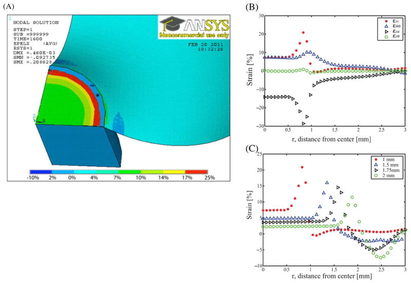
(A) Example finite element model of 3 mm radius well with nominal 1 mm radius post. Color intensity indicates calculated nodal strain in the radial direction for cut-away side view. Areas marked with star (*) indicate areas of the model where the post appears to penetrate the membrane due to the penetration tolerance of 0.1 in contact analysis. (B) Reported directional strains of εrr, εθθ εrθ and εzz along radial path on the x-axis on 1 mm radius of post. Note consistent biaxial strain out to ~0.7 mm radius. (C) Reported strain on the x-axis across same radial path varying the radius of post. Different markers denote varying post radius. As expected, the larger posts have a larger area of constant strain. However, the inner region (radius less than 0.7 mm) has constant strain values within 3% for every size post. Higher strains are possible by varying post sizes or pressures.
For the input parameter uncertainties, target strains can vary by up to 48.3% for the worst tolerance combination, e.g., the offset in a targeted 1.0 mm radius post mean strain of 6% can be ± 3% strain. These uncertainties provide theoretical bounds on the manufacturing variability from device to device for our existing fabrication processes and potential variability in PDMS properties [22, 25, 26]. Thus, our sensitivity analysis highlights the value of device calibration. There may be additional uncompensated error in our model due to our assumption of linear elastic behavior of the membrane. However, PDMS exhibits linear elastic behavior up to at least 200% strain [27, 28], well below our maximum predicted strain. The error due to ignoring viscoelasticity (less than 11% for one PDMS model [29]) is within our estimated variability of ~50%.
4.2 Calibration
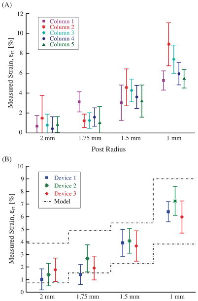
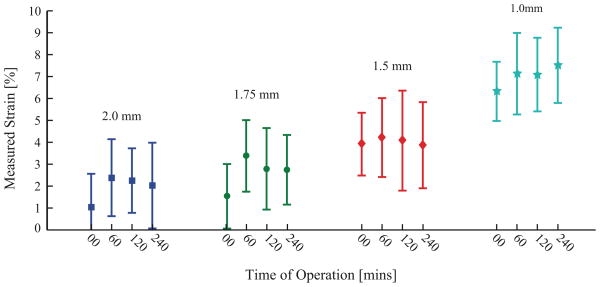
Different radii acrylic posts yield nominally distinct strain magnitudes for 10 kPa applied pressure difference profiles: 1%, 2%, 4%, and 6% for 2.0 mm, 1.75 mm, 1.5 mm, and 1.0 mm radius posts, respectively (figure 8). Calibration of three different devices yields variation within processing variability predicted by FEM sensitivity analysis (figure 8A). Examination of a single device (figure 8B) yields no detectable difference between wells of the same post radius (two-way ANOVA, p = 0.12) but a significant difference between well sets of different radii (p < 0.001). Again, as suggested by FEM, differences in acrylic post radius and spatial variations in modulus could account for the small differences seen between wells. Calibration values remained consistent for our target 4 hours of cyclic operation after being autoclaved (figure 9).
Figure 8.
Strains at 10kPa pressure difference. A) Mean and standard deviation strains for a single well size are determined by averaging the computed values of a Lagrangian strain matrix (n = 9). B) The resulting values are combined (n = 5) to obtain an overall device mean and standard deviation for principal strain in three separate devices.
Figure 9.
Calculated average strain over five wells on single device at 10 kPa pressure difference across the membrane after cyclic operation for designated period of time (1 Hz frequency, 10 kPa amplitude). Legend refers to radius of acrylic post.
4.3 Cell Studies on ISA
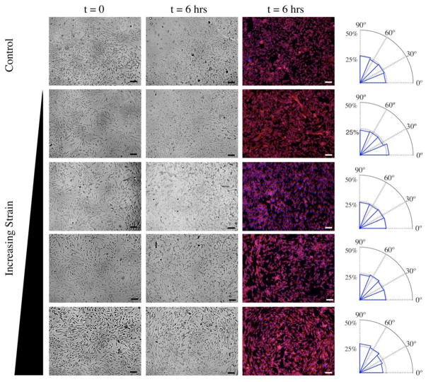
We have confirmed biocompatibility of the ISA for cell culture by maintaining healthy Madin-Darby Canine Kidney cells and C2C12 skeletal myoblasts on the device for over 5 days. To demonstrate that cells can be cultured under mechanical strain, we studied alignment of C2C12 cells. In several reports, isolated C2C12 and other cells have been observed to align perpendicular to cyclic uniaxial strains above 1 Hz, thereby minimizing the strain along the direction of stress fibers (actin filaments) [5, 6, 30, 31]. Under biaxial conditions, we also see the nuclei of C2C12 cells realign after cyclic loading at higher strains while they remain randomly oriented with low or no strain. Applied strain is thought to be transduced from the fibronectin-coated membrane to the cell through cell-matrix junctions made up of transmembrane integrins and intracellular linker proteins [32, 33]. Strain levels above a certain threshold induce cells to reorient axially along the direction of lower strain or perpendicular to the direction of higher strain [34, 35].
At higher strains, our C2C12 cells and their nuclei realign circumferentially, i.e., perpendicular (90°) to radial vectors as calculated by custom MATLAB code (last column of Figure 10). This is not surprising since for these biological demonstration studies, we did not constrain cells to the region of equibiaxial strain. Thus, cells near the post perimeter are exposed to higher radial strains (εrr > εθθ). Circumferential alignment is greatest at the outer perimeter and is consistent with realignment behavior under uniaxial cyclic loading. However, these data also suggest that a minimum biaxial strain imbalance is needed to trigger this cell reorientation. These data present opportunities for further investigation of protein complexes involved in cell-matrix and cell-cell adhesions. Cell-cell contacts may also be propagating the circumferential alignment found in the outer regions of anisotropic strain inward to the region of isotropic strain; this observation warrants further biological studies.
Figure 10.
Bright field and fluorescence images at t = 0 and t = 6 hrs after application of cyclic strain at a magnitude of 10 kPa pressure difference across the membrane magnitude and 1 Hz frequency. Scale bar = 100 μm. Nuclei and F-actin within the cells were stained with DAPI (blue) and rhodamine-phalloidin (red), respectively, and nucleus alignment was characterized by custom MATLAB code. Mean angular distribution of nucleus orientation (absolute angle between long axis of nucleus and radial vector to center of well) is depicted in the adjacent radial histogram (n = 5).
5. Conclusion
We have designed, fabricated and characterized an integrated strain array for cell culture that applies discrete strain levels across parallel populations of cells. The ISA enables high-throughput experiments amenable to open-well culture or compatible with microfluidic perfusion channels. We have demonstrated an array with 5 replicates of 5 strain levels, but in principle, the ISA can be expanded to a full 96 well plate with 1–96 discrete strain levels. While we achieved distinct strain levels of 1%, 2%, 4% and 6% with this preliminary design, more precise control over a wider range of strain magnitudes can be achieved with higher pressures and improved fabrication tolerances in future designs.
The ISA 96-well format maintains distinct cell populations and media for each sample and readily allows fluorescence imaging. We have demonstrated compatibility with standard cell culture techniques, including micropipette loading, maintenance, and fixing of cells for further biochemical assays and imaging. In this study, we fixed and stained the nucleus and F-actin in C2C12 cells. After stimulation on the ISA for six hours, C2C12 cells show circumferential realignment under 1 Hz cyclic biaxial loading above 4% strain, demonstrating the usefulness of the ISA for mechanotransduction investigations. Future biological investigations could use this system to examine the role of cell-matrix junction proteins in transmitting strain from the substrate to the cell and cell-cell junction proteins in transmitting strain to neighboring cells.
Acknowledgments
Special thanks to Elizabeth Martin, Daniel Hsu, and the rest of Stanford Microsystems for their help in the laboratory and to Professor Luke Lee at Berkeley for helpful discussions. This work was funded by the National Science Foundation, National Institutes of Health, and California Institute for Regenerative Medicine under grants NSF CAREER ECS0449400, NSF EFRI CBE0735551, NIH R21 HL089027, and CIRM RC1-00151-1. Additionally, individual authors were supported by NSF Graduate Research Fellowship (CS and AG), Stanford Cardiovascular Institute Smittcamp Fellowship (CS), BioX Fellowship at Stanford (JYS), Ilju Foundation Scholarship (JYS), and the American Heart Association (CC).
References
- 1.Banes AJ, Gilbert J, Taylor D, Monbureau O. A new vacuum-operated stress-providing instrument that applies static or variable duration cyclic tension or compression to cells in vitro. Journal of cell science. 1985;75:35–42. doi: 10.1242/jcs.75.1.35. [DOI] [PubMed] [Google Scholar]
- 2.Brown TD. Techniques for mechanical stimulation of cells in vitro: a review. Journal of Biomechanics. 2000;33:3–14. doi: 10.1016/s0021-9290(99)00177-3. [DOI] [PubMed] [Google Scholar]
- 3.Kim DH, Wong PK, Park J, Levchenko A, Sun Y. Microengineered platforms for cell mechanobiology. Annual Review of Biomedical Engineering. 2009;11:203–33. doi: 10.1146/annurev-bioeng-061008-124915. [DOI] [PubMed] [Google Scholar]
- 4.Yang S, Saif T. Reversible and repeatable linear local cell force response under large stretches. Experimental cell research. 2005;305:42–50. doi: 10.1016/j.yexcr.2004.12.026. [DOI] [PubMed] [Google Scholar]
- 5.Kamotani Y, Bersano-Begey T, Kato N, Tung YC. Individually programmable cell stretching microwell arrays actuated by a Braille display. Biomaterials. 2008 doi: 10.1016/j.biomaterials.2008.02.019. [DOI] [PMC free article] [PubMed] [Google Scholar]
- 6.Tan W, Scott D, Belchenko D, Qi HJ, Xiao L. Development and evaluation of microdevices for studying anisotropic biaxial cyclic stretch on cells. Biomedical Microdevices. 2008;10:869–82. doi: 10.1007/s10544-008-9201-8. [DOI] [PubMed] [Google Scholar]
- 7.Heo YJ, Iwase E, Matsumoto K, Shimoyama I. Stretchable Substrates for the Measurement of Intracellular Calcium Ion Concentration Responding to Mechanical Stress. Micro Electro Mechanical Systems, IEEE 22nd International Conference on; 2009. pp. 68–71. [Google Scholar]
- 8.Mukundan V, Pruitt BL. MEMS Electrostatic Actuation in Conducting Biological Media. Microelectromechanical Systems, Journal of. 2009;18:405–13. doi: 10.1109/JMEMS.2009.2013398. [DOI] [PMC free article] [PubMed] [Google Scholar]
- 9.Nishimura S, Yasuda S, Katoh M, Yamada KP, Yamashita H, Saeki Y, Sunagawa K, Nagai R, Hisada T, Sugiura S. Single cell mechanics of rat cardiomyocytes under isometric, unloaded, and physiologically loaded conditions. Am J Physiol Heart Circ Physiol. 2004;287:H196–202. doi: 10.1152/ajpheart.00948.2003. [DOI] [PubMed] [Google Scholar]
- 10.Moraes C, Chen J, Sun Y, Simmons CA. Microfabricated arrays for high-throughput screening of cellular response to cyclic substrate deformation. Lab on a Chip. 2010;10:227–34. doi: 10.1039/b914460a. [DOI] [PubMed] [Google Scholar]
- 11.Serrell DB, Oreskovic TL, Slifka AJ, Mahajan RL, Finch DS. A uniaxial bioMEMS device for quantitative force-displacement measurements. Biomedical Microdevices. 2007;9:267–75. doi: 10.1007/s10544-006-9032-4. [DOI] [PubMed] [Google Scholar]
- 12.Estes BT, Gimble JM, Guilak F. Mechanical signals as regulators of stem cell fate. Current Topics in Developmental Biology. 2004;60:91–126. doi: 10.1016/S0070-2153(04)60004-4. [DOI] [PubMed] [Google Scholar]
- 13.Ehrlich PJ, Lanyon LE. Mechanical strain and bone cell function: a review. Osteoporosis international: a journal established as result of cooperation between the European Foundation for Osteoporosis and the National Osteoporosis Foundation of the USA. 2002;13:688–700. doi: 10.1007/s001980200095. [DOI] [PubMed] [Google Scholar]
- 14.Wang JH, Thampatty BP. An introductory review of cell mechanobiology. Biomech Model Mechanobiol. 2006;5:1–16. doi: 10.1007/s10237-005-0012-z. [DOI] [PubMed] [Google Scholar]
- 15.Huh D, Matthews BD, Mammoto A, Montoya-Zavala M, Hsin HY, Ingber DE. Reconstituting organ-level lung functions on a chip. Science. 328:1662–8. doi: 10.1126/science.1188302. [DOI] [PMC free article] [PubMed] [Google Scholar]
- 16.Ahmed WW, Kural MH, Saif TA. A novel platform for in situ investigation of cells and tissues under mechanical strain. Acta biomaterialia. 6:2979–90. doi: 10.1016/j.actbio.2010.02.035. [DOI] [PMC free article] [PubMed] [Google Scholar]
- 17.Colombo A, Cahill PA, Lally C. An analysis of the strain field in biaxial Flexcell membranes for different waveforms and frequencies. Proceedings of the Institution of Mechanical Engineers Part H. 2008;222:1235–45. doi: 10.1243/09544119JEIM428. [DOI] [PubMed] [Google Scholar]
- 18.Bieler FH, Ott CE, Thompson MS, Seidel R, Ahrens S, Epari DR, Wilkening U, Schaser KD, Mundlos S, Duda GN. Biaxial cell stimulation: A mechanical validation. Journal of Biomechanics. 2009;42:1692–6. doi: 10.1016/j.jbiomech.2009.04.013. [DOI] [PubMed] [Google Scholar]
- 19.Wang D, Xie Y, Yuan B, Xu J, Gong P, Jiang X. A stretching device for imaging real-time molecular dynamics of live cells adhering to elastic membranes on inverted microscopes during the entire process of the stretch. Integrative biology: quantitative biosciences from nano to macro. 2:288–93. doi: 10.1039/b920644b. [DOI] [PubMed] [Google Scholar]
- 20.Baechtold P, Simmons CA, Sim JY, Haniff S, Pruitt BL. Strain Array for Cell Culture. Proceedings of MicroTAS; Jeju, South Korea. 2009. [Google Scholar]
- 21.Carrillo Nanoindentation of polydimethylsiloxane elastomers: Effect of crosslinking, work of adhesion, and fluid environment on elastic modulus. J Mater Res. 2005;20:2820–30. [Google Scholar]
- 22.Fuard D, Tzvetkova-Chevolleau T, Decossas S, Tracqui P, Schiavone P. Optimization of poly-di-methyl-siloxane (PDMS) substrates for studying cellular adhesion and motility. Microelectronic Engineering. 2008;85:1289–93. [Google Scholar]
- 23.Sasoglu FM, Bohl AJ, Layton BE. Design and microfabrication of a high-aspect-ratio PDMS microbeam array for parallel nanonewton force measurement and protein printing. Journal of Micromechanics and Microengineering. 2007;17:623–32. [Google Scholar]
- 24.Blau HM, Pavlath GK, Hardeman EC, Chiu CP, Silberstein L, Webster SG, Miller SC, Webster C. Plasticity of the differentiated state. Science. 1985;230:758–66. doi: 10.1126/science.2414846. [DOI] [PubMed] [Google Scholar]
- 25.Sasoglu F, Bohl A, Layton B. Design and microfabrication of a high-aspect-ratio PDMS microbeam array for parallel nanonewton force measurement and protein printing. Journal of Micromechanics and Microengineering. 2007;17:623. [Google Scholar]
- 26.Carrillo F, Gupta S, Balooch M, Marshall S, Marshall G, Pruitt L, Puttlitz C. Nanoindentation of polydimethylsiloxane elastomers: Effect of crosslinking, work of adhesion, and fluid environment on elastic modulus. Journal of materials research. 2005;20:2820–30. [Google Scholar]
- 27.Huang R, Anand L. Innovation in Manufacturing Systems and Technology (IMST) 2005. Non-linear mechanical behavior of the elastomer polydimethylsiloxane (PDMS) used in the manufacture of microfluidic devices. [Google Scholar]
- 28.Drozdov A, Christiansen J. Constitutive equations for the nonlinear elastic response of rubbers. Acta Mechanica. 2006;185:31–65. [Google Scholar]
- 29.Lin I, Liao Y, Liu Y, Ou K, Chen K, Zhang X. Viscoelastic mechanical behavior of soft microcantilever-based force sensors. Applied Physics Letters. 2008;93:251907. [Google Scholar]
- 30.Wang DL, Wung BS, Shyy YJ, Lin CF, Chao YJ. Mechanical Strain Induces Monocyte Chemotactic Protein-1 Gene Expression in Endothelial Cells. Circulation research. 1995;77:294–302. doi: 10.1161/01.res.77.2.294. [DOI] [PubMed] [Google Scholar]
- 31.Liu B, Qu MJ, Qin KR, Li H, Li ZK, Shen BR, Jiang ZL. Role of cyclic strain frequency in regulating the alignment of vascular smooth muscle cells in vitro. Biophysical Journal. 2008;94:1497–507. doi: 10.1529/biophysj.106.098574. [DOI] [PMC free article] [PubMed] [Google Scholar]
- 32.Schwartz MA, DeSimone DW. Cell adhesion receptors in mechanotransduction. Current opinion in cell biology. 2008;20:551–6. doi: 10.1016/j.ceb.2008.05.005. [DOI] [PMC free article] [PubMed] [Google Scholar]
- 33.Chen CS, Tan JL, Tien J. MECHANOTRANSDUCTION AT CELL-MATRIX AND CELL-CELL CONTACTS. Annual Review of Biomedical Engineering. 2004;6:275–302. doi: 10.1146/annurev.bioeng.6.040803.140040. [DOI] [PubMed] [Google Scholar]
- 34.Wang H, Ip W, Boissy R, Grood ES. Cell orientation response to cyclically deformed substrates: experimental validation of a cell model. Journal of Biomechanics. 1995;28:1543–52. doi: 10.1016/0021-9290(95)00101-8. [DOI] [PubMed] [Google Scholar]
- 35.Barron V, Brougham C, Coghlan K, McLucas E, O’Mahoney D, Stenson-Cox C, McHugh PE. The effect of physiological cyclic stretch on the cell morphology, cell orientation and protein expression of endothelial cells. Journal of materials science: Materials in medicine. 2007;18:1973–81. doi: 10.1007/s10856-007-3125-3. [DOI] [PubMed] [Google Scholar]


