Abstract
Modelling the interactions of biological molecules, or docking, is critical both to understanding basic life processes and to designing new drugs. The field programmable gate array (FPGA) based acceleration of a recently developed, complex, production docking code is described. The authors found that it is necessary to extend their previous three-dimensional (3D) correlation structure in several ways, most significantly to support simultaneous computation of several correlation functions. The result for small-molecule docking is a 100-fold speed-up of a section of the code that represents over 95% of the original run-time. An additional 2% is accelerated through a previously described method, yielding a total acceleration of 36× over a single core and 10× over a quad-core. This approach is found to be an ideal complement to graphics processing unit (GPU) based docking, which excels in the protein–protein domain.
1 Introduction
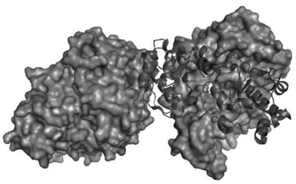
A fundamental operation in biochemistry is the interaction of molecules through non-covalent bonding, or docking (see Fig. 1). Modelling molecular docking is critical both to evaluating the effectiveness of pharmaceuticals and to developing an understanding of life itself. Docking applications are computationally demanding. In drug design, millions of candidate molecules may need to be evaluated for each molecule of medical importance. As each evaluation can take many CPU-hours, huge processing capability must be applied; production facilities typically use large clusters.
Figure 1. Docked complex of two proteins generated using Pymol [8].
Although accelerating docking using heterogeneous parallel processors has clear and obvious benefits, there has been surprisingly little work thus far. SymBioSys uses the cell broadband engine in their eHITS software [1], and Servat et al. [2] report using the same processor to accelerate the FTDock code. With GPUs, the only published work so far appears to be in a dissertation by Korb [3] and work by Sukhwani and Herbordt [4]. Korb accelerates the structure transformation and scoring function evaluation phases. Our GPU work accelerates the PIPER docking code [5]; we summarise this below and compare it with the FPGA approach presented here. The present authors and collaborators have also previously used FPGAs to demonstrate proof-of-concept FPGA-based acceleration of ZDOCK and some other systems [6, 7].
The basic computational task for docking is to find the relative offset and rotation (pose) between a pair of molecules that gives the strongest interaction (see Fig. 2). Hierarchical methods are often used; these include: (i) an initial phase where candidate poses are determined (docking) and (ii) an evaluation phase where the quality of the highest scoring candidates is rigorously evaluated. This work describes the FPGA-based acceleration of PIPER, a state-of-the art code that performs the first of these tasks. PIPER advances the art of rigid molecule docking by minimising the number of candidates needing detailed scoring with only modest added complexity [5]. Our methods are general, however, and can be applied to other rigid molecule docking codes.
Figure 2. Examples of shape complementarity (from [6]).
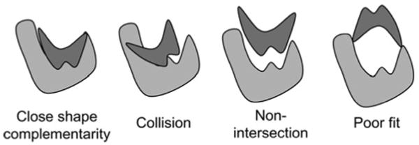
Many docking applications including PIPER assume, at least initially, a rigid structure (see Fig. 2). This still allows modelling of various force laws that govern the interaction between molecules, including geometric, electrostatic, atomic contact potential and others. A standard technique maps the molecules' characteristics to three-dimensional (3D) grids. The most energetically favourable relative position is determined by summing the voxel–voxel interaction values for each modelled force at all positions to generate a score, and then repeating this for all possible translations and rotations. Some other well known rigid molecule docking codes with public domain servers are Situs [9], FTDock [10], ZDOCK [11], Hex [12], GRAMM [13], DOT [14] and PatchDock [15]. Some of the many docking codes that use rigid molecule docking as a preliminary step are Glide [16], ClusPro [17] and GRAMM-X [18].
The computational complexity of rigid molecule docking is large. With typical grid sizes of N = 128 in each dimension and 10 000 rotation angles, 1010 relative positions are evaluated for a single molecule pair. Typically, the outer loop consists of the rotations while the translations are handled with a 3D correlation. Since the latter require O(N6) operations, this type of exhaustive search was long thought to be computationally infeasible [19]. The introduction of the FFT to docking [20] reduced the complexity of each 3D correlation to O(N3 log N) for steric (shape only) models; further work expanded the method to electrostatic [10] and solvation contributions [11].
Docking computations are generally used to model one of two types of interactions: between proteins (protein–protein docking) or between a protein or other large molecule and a small molecule (small molecule docking). In the latter case the large molecule is referred to as the substrate or receptor and the small molecule as the ligand. Protein–protein docking is important for basic science, whereas small molecule docking is the method of primary interest in drug discovery. In both cases, one molecule has a grid size of up to 1283; in protein–protein the second molecule is similar, but in small molecule the ligand is typically an order of magnitude smaller (per dimension). This difference leads to there being a divergence in optimisations, with docking codes sometimes specialising in one domain or the other. We have found that this divergence emerges in accelerated docking as well.
In our previous work [6, 7] we showed that, for FPGA-based coprocessors, the original direct correlation – rather than an FFT – is sometimes the preferred method for computing rigid molecule docking. Two reasons for this are the inherent efficiency with which FPGAs perform convolutions and the modest precision (2–7 bits) of the original voxel data. Note that this precision goes to 48 or 106 bits (single or double precision imaginary floating point) for the FFT. We also introduced a novel addressing technique for performing rotation that uses only a modest amount of logic, and whose latency can be entirely hidden. Finally, we presented an efficient filtering method that computes on-the-fly the biological importance of the poses and so minimises host–accelerator communication.
In this work, we extend these methods to facilitate integration into PIPER and other docking codes. In particular, we have added support for (i) pairs of large molecules as necessary for modelling protein–protein interactions; previously we only supported protein interactions with small molecules, (ii) the efficient combining of a potentially large number of force models; previously we had flexibility in the force model, but required it to be simple and (iii) handling charge reassignment after every rotation; previously we assumed that charge assignment was done only once. The result is, for small-molecule docking, a 100-fold speed-up of PIPER's correlation computation and a ten-fold speed-up of the entire application. Both these numbers are with respect to a four-core processor.
In this work, we also find the limits of the correlation-based approach for current generation FPGAs. Since the FFT has the advantage over direct convolution in asymptotic complexity, the question is at what molecule size does this advantage begin to dominate over other factors, such as precision. We find that the split occurs almost directly on the small/large molecule boundary. For ligands less than 253, direct correlation yields significant acceleration; for ligands larger than 323, the FFT, on a multicore host, is superior.
The particular contributions are modified structures to support these features and the experiments that determine the optimal configuration with respect to several design parameters. The overall significance is to reduce the typical running time of evaluating a drug candidate from days to hours thereby dramatically increasing the throughput of computational docking experiments. Further significance is the finding with respect to the cross-over point between 3D correlations and FFTs on FPGAs. This could be of interest in many other applications where these operations are fundamental. Finally, the comparison with multicore processors and with GPUs points to the best ways to build cost-effective heterogeneous rigid-molecule docking systems using the current generation of accelerator technology.
The rest of this paper is organised as follows. We next give a brief overview of PIPER. There follows the basic design for 3D correlation on the FPGA. After that we present details of the novel structures needed to implement complex correlations. Then comes a summary of other approaches possible using FPGAs, GPUs and multicore. We conclude with results, a comparison of approaches and discussion.
2 PIPER docking program
2.1 Overview
A primary consideration in docking is preventing the loss of near-native solutions (false negatives); as a result, rigid molecule codes tend to retain a large number (thousands) of docked conformations for further analysis even though only a few hundred will turn out to be true hits. ‘Improving these methods remains the key to the success of the entire procedure that starts with rigid body docking [5]’. PIPER addresses this issue by augmenting commonly used scoring functions (shape, electrostatics) with a desolvation computed from pairwise potentials; the rest of this section is based on the primary reference to that system [5].
Pairwise potentials represent interactions of atoms (or residues) on the interacting molecules. Different pairs of atoms have different values; these are empirically determined (and sometimes called knowledge based). For K atom types, there is a K × K interaction matrix; each column (or row) can be handled with a single correlation resulting in K forward and one reverse FFT. Since K is generally around 20 (and up to 160), and since the FFT dominates the computation, use of pairwise potentials could drastically increase run time. A fundamental innovation in PIPER is the finding that eigenvalue-eigenvector decomposition can substantially reduce this added complexity. In particular, ‘adequate accuracy can be achieved by restricting consideration to the eigenvectors corresponding to the P largest eigenvalues where 2 ≤ P ≤ 4, and thus performing only 2–4 forward and one reverse FFT calculations’. In practice, however, up to 18 terms are sometimes used.
PIPER's energy-like scoring function is computed for every rotation of the ligand (smaller molecule) with respect to the receptor (larger molecule). It is defined on a grid and is expressed as the sum of P correlation functions for all possible translations α, β, γ of the ligand relative to the receptor
| (1) |
where Rp(i, j, k) and Lp(i + α, j + β, k + γ) are the components of the correlation function defined on the receptor and the ligand, respectively.
For every rotation, PIPER computes the ligand energy function Lp on the grid and performs repeated FFT correlations to compute the scores for different energy functions. For each pose, these energy functions are combined to obtain the overall energy for that pose. Finally, a filtering step returns some number of poses based on score and distribution.
2.2 PIPER scoring functions
The scoring function used in PIPER is based on three criteria: shape complementarity (SC), electrostatic energy and desolvation energy (through pairwise potentials). Each of these is expressed as a 3D correlation sum, and the total energy function is expressed as a weighted sum of these correlation scores
| (2) |
SC refers to how well the two proteins fit geometrically (see Fig. 2) and here is computed as a weighted sum of attractive and repulsive van der Waals (Pauli exclusion) terms, the latter accounting for atomic overlaps: Eshape = Eattr + w1Erep.
Electrostatic interaction between the two proteins is represented in terms of a simplified Generalised Born (GB) equation [11]. The electrostatic energy is obtained as a correlation between the charge on the ligand grid and the potential field on the receptor grid. Unlike in our previous work, charge distribution is recomputed for every rotation.
Desolvation is a measure of change in free energy when a protein–atom/water contact is replaced by a protein–atom/protein–atom contact. In PIPER, it is represented using pairwise interaction potentials, as previously discussed, through P correlation functions.
2.3 PIPER program flow and performance profile
Fig. 3 shows the sequence of steps followed by the PIPER program to perform docking of a ligand to a receptor. The ligand and receptor atoms are read from input files, along with certain parameters and coefficients. These are used in scoring, filtering top scores, rotation and charge assignment. Next, PIPER determines the size of the padded FFT grid (based on the sizes of the ligand and receptor) and generates the receptor and ligand grids for the various energy functions. Then the receptor grids for the energy functions are assigned values and their forward FFTs and complex conjugates are computed. The number of forward FFTs to be performed equals P + 4. The ‘4’ are the following: attractive van der Waals, repulsive van der Waals, Born component of electrostatic energy and Coulomb component of electrostatic. The ‘P’s are the top P desolvation terms.
Figure 3. Program flow of PIPER.
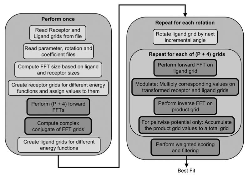
Blocks in dark grey with bold border indicate steps accelerated on the FPGA
For each rotation, PIPER multiplies the ligand with the next rotation vector and assigns new values to ligand grids for different energy functions. We leave these two steps to be performed on the host. After grid assignment, forward FFTs of each ligand grid are performed and the transformed grid is multiplied with the corresponding transformed receptor grid. The multiplied grid is then inverse transformed. For the case of the desolvation terms, the inverse transformed grids are accumulated to obtain the total score for desolvation energy. A weighted sum of the scores for the various energy functions is then computed and the top scores reported. In our FPGA accelerated version, we perform all the per-rotation steps – except rotation and grid assignment – in the FPGA. This accelerates the bulk of the work performed by PIPER (see Table 1), but bounds the potential speed up at about 40×. Accelerating charge assignment is also possible using the methods developed previously [21]. Note that the FPGA accelerated version, the steps of FFT, modulation and inverse FFT are replaced with direct correlation.
Table 1. PIPER run times for one rotation using a single core of a 2008 2 GHz quad-core Xeon processor.
| Phase | Run time (s) | % total |
|---|---|---|
| ligand rotation | 0.00 | 0 |
| charge assignment | 0.23 | 2.3 |
| FFT of ligand grids | 4.51 | 45.4 |
| modulation of grid pairs | 0.22 | 2.2 |
| IFFT of ligand grids | 4.51 | 45.4 |
| accumulation of desolvation terms | 0.24 | 2.4 |
| scoring and filtering | 0.23 | 2.3 |
| Total | 9.94 | 100 |
P = 18 so 22 correlations are computed. Steps performed once are negligible over thousands of iterations
3 Correlation structure
Fig. 4 shows the systolic 3D correlation array progressively formed starting from a 1D correlation array [7]. This structure is an extension of the 2D correlation array described in [22]. The systolic array performs direct correlation at streaming rate. The basic unit of the systolic array is a compute cell which takes two voxels and computes the voxel–voxel score. The compute cell then adds this score to the partial score from the previous cell and outputs the updated partial score. The operation of the compute cell can be written as
Figure 4. Structures to compute 3D correlations.
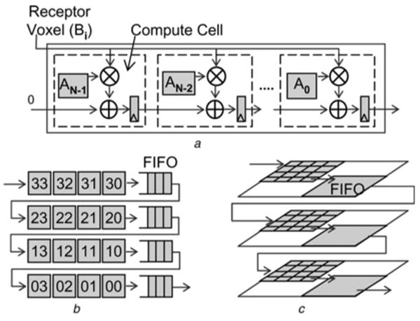
a standard 1D systolic array
b extension to 2D extension with delay lines
c full 3D correlation with delay planes
where Scorein is the score from the previous compute cell and F(VoxelA, VoxelB) is the function between the two voxels. For correlation, F(VoxelA, VoxelB) translates to a product between the two voxels, making the compute cell a simple multiply-accumulate unit (Fig. 4a). In our original implementation, voxels for the ligand grid are stored in the compute cells on the FPGA and the voxels of the receptor grid are streamed through it, generating one correlation score per cycle. In this work we have extended the design to support complex correlations (Sections 4.1 and 4.2) and two large molecules (see Section 4.3).
As shown in Fig. 4a, the 1D correlation structure consists of pipelined compute cells. Every clock cycle two things happen: one receptor voxel is broadcast to every cell, and the partial scores computed by each cell are passed to the next cell. The last compute cell generates the total row score. An advantage of direct correlation is that the function F(VoxelA, VoxelB) can be non-linear; the FFT method can only handle linear functions.
The number of scores generated by each 1D correlation is (Nx + Mx − 1), where Nx and Mx are the sizes of the two grids along the x-axis. To form a 2D correlation plane by connecting multiple 1D correlation rows, the scores from different 1D rows need to be aligned. This is done by delaying each row score by (Nx + Mx − 1) cycles before feeding it to the next row. A delay of Nx is inherently provided by the compute cells. To delay the scores by the remaining Mx − 1 cycles, 1D line FIFOs are used. Similarly, connecting multiple 2D correlation planes to form a 3D space requires plane FIFOs of size (Mx + Nx − 1) × (Ny − 1).
On typical high-end FPGAs, these first in, first outs (FIFOs) can be implemented using block RAMs. Note that the size of the FIFO is proportional to the size of the larger grid Mx. In addition, since the FIFOs are used to delay the correlation score, the width of the FIFOs depends on the number of bits the correlation score requires. Although enough block RAMs are present to implement FIFOs for grids of quite large size, incorporating multiple correlations can pose a problem. This is discussed in the next section and a modified correlation pipeline is proposed.
4 FPGA algorithms
4.1 Supporting multiple energy functions: overview
There are two obvious ways to extend the structure of Section 3 to combine the multiple correlations required of PIPER: compute them singly or together. Neither is by itself preferred. The first method uses the same control structure as before, but, for each different correlation, the FPGA is reconfigured to the appropriate data types and energy model. The scores must be saved off-chip and combined. That is, the k FFTs are replaced with k correlations, plus the overhead of reconfiguration and combining. The second method involves expanding the structure to perform k different correlations simultaneously. This method requires only a single pass through the large grid, and generates k independent correlation scores per cycle. Recall from Section 2.2, however, that the energy functions are weighted so that for k functions
| (3) |
Thus combining on-the-fly requires multiplications as well as additions, resulting in (perhaps) a substantially more complex compute structure. Combining can be done in three ways: within each compute cell, upon completion or by integrating the weights into the scoring functions. These options are now examined (see Fig. 5).
Figure 5. Shown are three methods of combining multiple correlations in a single pass.
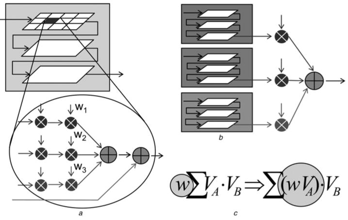
a Within a compute cell
b Upon completion
c Integrated into the scoring function
Combining within the compute cells requires that the weighted sums be computed within each one. This makes the compute cell more complex (see Fig. 5a). For each energy function, the first multiplier multiplies the two voxels to generate the score, which is then multiplied with the appropriate weight. Weighted scores of different energy functions are summed up and added to the weighted score from the previous cell. The problem here is the number of multipliers that this requires: 2k times the number of cells, or between 512 and 4000 additional multipliers. This is problematic for current FPGAs and would end up drastically reducing the number of compute cells and hence the size of the largest ligand grid that can be supported.
Combining on completion (see Fig. 5b) means that we must propagate k independent running scores through the line and plane FIFOs of Fig. 4; the width of the FIFOs must then be increased by k×. Even with average sized grids, the block RAM requirements to implement the FIFOs are way over the available block RAMs on present day FPGAs, making this approach impractical.
Integrating the weights into the grids (see Fig. 5c) requires significantly increasing the precision throughout the entire system. This reduces the number of compute cells and thus the throughput. While a plausible solution, it is still not preferred.
4.2 Supporting multiple energy functions: augmented structure
The solution we use is a hybrid: we compute all the energy functions simultaneously and we combine the running scores once per row (see Fig. 6). The resulting structure results in an almost 40% savings in block RAM requirements compared to the solution in Fig. 5b and almost 38% reduction in multipliers compared to Fig. 5a, for typical receptor-ligand grid sizes. To obtain the augmented structure, the following modifications are required in the correlation structure of Fig. 4.
Figure 6. Shown is the 2D correlation pipeline modified to support complex correlations.
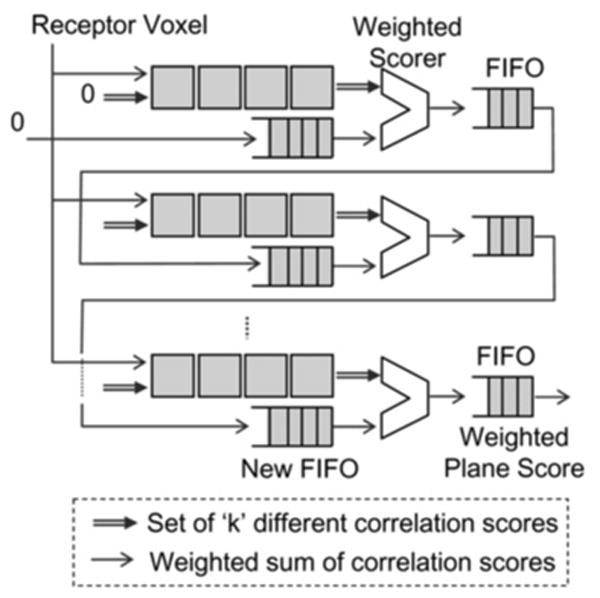
The 3D extension is analogous
4.2.1 Modified compute cell
The basic compute cell has been extended to compute multiple correlation functions per cycle. Each cell performs k independent multiply accumulate operations and outputs k independent partial correlation scores.
4.2.2 Weighted Scorer
At the end of each 1D correlation row, a new weighted scorer module is added. It takes k independent partial correlation scores (generated by the current 1D correlation row) and the partial weighted score from the previous row and computes a new partial weighted score. It also checks for saturation of individual scores, setting them to the positive or negative saturation value if needed. The partial weighted score is then sent to the line FIFO. Note that the FIFO now carries only one score as opposed to k. To obtain a high operating frequency, the computation is pipelined into three stages, as shown in Fig. 7.
Figure 7. Shown is detail of the end-of-row weighted scorer.
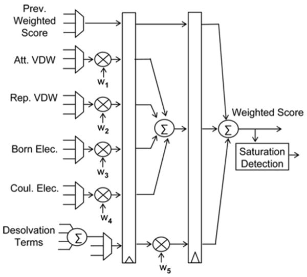
It is pipelined to enable high operating frequency
4.2.3 New FIFO
The scores entering and leaving the FIFO are now weighted sums of individual correlation scores. The scores computed by the compute nodes are still the k individual correlation sums. Thus, compute cells cannot simply add the output of the FIFO to their current score. This distinction requires a modification in the existing pipeline and the compute cells. The compute rows no longer receive the partial correlation score from the FIFO; instead, a zero is fed into the first cell of each compute row. The weighted score from the FIFO of the current row is sent directly to the weighted scorer module at the end of the next row, where it is added to the partial weighted score of that row (as per (3)). In order to align this previous weighted score with the scores emerging from the current row, it needs to be sent through a new FIFO before it enters the weighted scorer. The length of this new FIFO is equal to the length of the 1D correlation row. For efficient implementation, this new FIFO is merged with the existing line FIFO. Also, the length of the combined FIFO needs to be adjusted to account for the delay through the pipeline stages of the weighted scorer.
4.2.4 New voxel data type
In contrast to the earlier design, where each voxel represented only one value, the new voxel data at every grid point must represent energy values for different energy functions. To implement the PIPER energy functions, we have modified the voxel data to contain the following five (or more) energy values: attractive van der Waals, repulsive van der Waals, Born electrostatics, Coulomb electrostatics, and P pairwise-potentials. The number of desolvation terms, P, is an input parameter.
In the serial PIPER code, the energies are represented using single precision floating point numbers. In our FPGA implementation, we use the fixed point numbers shown in Table 2 with no loss of precision.
Table 2. Number of bits per voxel for computing various energy functions.
| Energy term | Data type | Number of bits | |
|---|---|---|---|
| Receptor | Ligand | ||
| attractive van der Waals | integer | 8 | 4 |
| repulsive van der Waals | integer | 4 | 4 |
| electrostatics | fixed point | 9 | 9 |
| pairwise potentials | fixed point | 9 | 9 |
4.3 Supporting large ligands
In order to support larger ligand grids, we have implemented a scheme to compute correlation scores in pieces. Note that the receptor size can still be as large as before. We call this piece-wise correlation, as it involves loading different pieces of the ligand grid into the FPGA correlation cores and storing the partial scores in score memory. A new ligand memory is added which stores the entire ligand. This was not needed earlier since ligand volxels were stored directly in the compute cells. For each ligand piece, the receptor is streamed through the 3D correlation pipeline and the partial scores are saved. We have added a new controller to handle the new functions: loading ligand grid-pieces, generating the correlation scores, and generating the addresses of score memory where the current partial scores are accumulated. A new-score accumulator has also been added. This fetches the current score from the score memory, adds the new partial score to it, and stores it back to the same location in score RAM. The entire scheme is shown in Fig. 8.
Figure 8. Block diagram of piece-wise docking for computations with large second molecules.
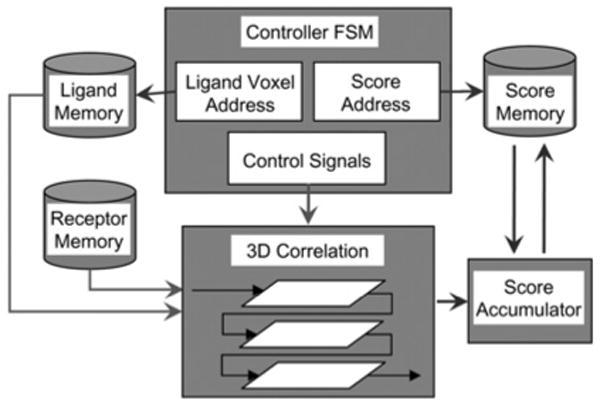
Table 3 compares the logic utilisations for the correlation pipelines with and without support for piecewise correlation. For this example, a simple compute cell is used with an 8 × 8 × 8 on-chip array of cells. The designs in the first two rows both operate on an 8 × 8 × 8 ligand; the difference is that the second has the overhead hardware for swapping. We see that the overhead for supporting piecewise correlation is minimal. Also, the clock rate is virtually unchanged. The last two rows show the support required to operate on 163 and 323 ligands, respectively, keeping the number of hardware cells constant. Clearly, larger correlations can be supported without much increase in the resources required.
Table 3. Resource utilisation for piecewise correlation for the Altera Stratix-III family.
| Design | Resource utilisation | |
|---|---|---|
| ALUTs | Registers | |
| no piecewise support 8 × 8 × 8 ligand | 14650 | 15694 |
| piecewise support 8 × 8 × 8 ligand | 14987 | 15920 |
| piecewise support 16 × 16 × 16 ligand | 15035 | 15934 |
| piecewise support 32 × 32 × 32 ligand | 15132 | 15953 |
There is little overhead due to piecewise support
5 Results
5.1 Target architecture and operation
The target architecture for FPGA-accelerated PIPER described here has the following characteristics (typical for current products):
The overall system consists of a host PC or workstation with an accelerator board plugged into a high-speed socket (e.g. PCI Express). The host runs the main application program and communicates with the accelerator through function calls using vendor supplied drivers.
The accelerator board consists of a high-end FPGA, memory and a bus interface. On-board memory is tightly coupled to the FPGA either through several interfaces (e.g. 6 × 32-bit) or a wide bus (128-bit).
Besides configurable logic, the FPGA has dedicated components such as independently accessible multiport memories (e.g. 1000 × 1 KB) and a similar number of multipliers.
Generalising PIPER to multi-FPGA systems for most docking applications is almost immediate: rotations can be partitioned among accelerators.
Execution of the accelerated code proceeds as follows. Before the correlation between the receptor and ligand grids is performed, those grids need to be assigned with charges corresponding to the various energy functions. This is done on the host using the PIPER code. For the receptor, PIPER assigns the charges only once, since it stays fixed throughout the entire docking process. This grid is downloaded to the accelerator board memory. For every rotation, the PIPER program rotates the ligand and updates charges on the ligand grid. This grid is then downloaded into the correlation cells on the FPGA. In the case of piecewise correlation, the ligand grid is downloaded into off-chip memory, whence it is loaded as described in Section 4.3.
Once the ligand is downloaded, the FPGA correlation starts, generating one score per cycle. These scores are passed to a data reduction filter, which selects a pre-specified number of top scoring positions and stores them in the on-chip block RAMs. Upon completing the correlations for one rotation, the host program uploads the highest scores and downloads the ligand grid for the next rotation.
Each FPGA accelerator has a certain capacity of correlation cells, for example, 83 for the Altera Stratix-III SL340 when running PIPER with P = 4. For larger ligands and larger P, the cell array is used multiple times per rotation (piece-wise correlation). For smaller ligands and simpler energy functions, multiple correlations are executed simultaneously, for example, 8 for a 43 ligand.
We now briefly describe the non-FPGA overhead, including data transfers.
Initialisation: initialisation can take several seconds, but since the overall execution time is on the order of hours, this time is negligible.
Host computation: charge is reassigned to the ligand for every new rotation. For typical ligand sizes this takes 200 ms and can proceed in parallel with the FPGA computation.
Host-board data transfers: after initialisation, the only data transfers between host and FPGA board are the ligand (host-to-board) and results (board-to-host). Both are negligible. The data per ligand is the bytes per voxel (e.g. 8 for P = 4) times the number of voxels (e.g. 83). The results are the few highest scoring positions and their scores.
Board-FPGA data transfers: during correlation, receptor data are streamed from board to FPGA in a single stream. Again, this is 8 bytes wide for P = 4, which represents a fraction of typical board-FPGA transfer capability.
5.2 Validation and FPGA-specific results
All FPGA configurations were created using VHDL. Synthesis and place-and-route were performed using Altera design tools. The target system used to validate the functionality of FPGA-accelerated PIPER was an XtremeData XD1000, which contains an Altera Stratix-II EP2S180 [23]. Validation was performed with respect to the original PIPER serial code: exact matches were obtained.
Since the Stratix-II is now obsolete we also generated configurations through post place-and-route for an Altera Stratix-III EPSL340. This method is sufficient to give precisely the resource usage (see Table 4). For an 83 ligand, the design uses 100% of the DSP blocks and 82% of the combinational logic. The actual number of multipliers required is far more than those available on the chip: the balance are created from combinational logic. The operating frequency is predicted to be 100 MHz. For true implementations this number is often slightly lower. On the other hand, operating frequencies for this generation FPGA are often in the 200–300 MHz range, so with some optimisation higher performance could be realised.
Table 4. Resource utilisation per cell for various energy functions.
| Energy function | Number of correlations | Cell operation | Resources used | ||
|---|---|---|---|---|---|
| ALUTs | Registers | DSPs | |||
| SC (2 bits) | 1 | bitwise AND | 15 | 17 | 0 |
| SC + desolvation (ZDOCK) | 2 | bitwise operations | 50 | 41 | 0 |
| SC + electrostatics (FTDock, DOT) | 2 | bitwise ops + one multiplication | 32 | 74 | 1 |
| PIPER energy function w/o pairwise potential | 4 | bitwise ops + two multiplications | 59 | 97 | 2 |
| PIPER energy function w/two pairwise potentials | 6 | bitwise ops + four multiplications | 93 | 109 | 4 |
| PIPER energy function w/four pairwise potential | 8 | bitwise ops + six multiplications | 127 | 157 | 6 |
5.3 Reference codes
Besides the original single core and FPGA-accelerated versions of PIPER, we have constructed two other versions: a multithreaded and a GPU accelerated. They differ primarily in the correlation: specifically in the cross-over point where the FFT is preferred over direct computation. In all cases, the host was a quad-core Intel Xeon 2 GHz processor. The host codes were compiled using standard optimisation settings. Docking results were validated against the original code.
For FPGAs, the reasons to implement correlations directly, rather than with an FFT, include low precision and a regular compute pipeline. The FFT's advantage in asymptotic complexity, however, means that there must exist a problem size where that method is preferred. Conversely, for multicore and GPU there may also exist problem sizes small enough for direct correlation to be preferable to the FFT.
Our reference implementation, the PIPER production code, uses the FFTW package [24]. Running this on a single core of a quad-core Intel Xeon 2 GHz processor, the time for a 1283 FFT is 360 ms. When all four cores are used, the time is 106 ms. Direct correlation on multicore is slower for all ligand sizes greater than 43, which executes in 44 ms. In separate work, we performed the same 3D FFT on a current high-end GPU-based system, the NVIDIA Tesla C1060 (see [4] for details). The Tesla C1060 has a PCIe interface, 4 GB of memory and a single GPU. The GPU itself has an operating frequency of 1.3 GHz and 240 streaming processor cores. For this system, using the NVIDIA library function, the time for a 1283 FFT is 9.3 ms. We also tried direct correlation: this was again slower than the FFT for all ligand sizes but 43, which executes in 4.1 ms.
5.4 Performance comparisons
5.4.1 Performance with respect to various energy functions
Rigid-molecule docking programs vary in their energy functions. For example, Situs [9] employs SC, whereas FTDock [10], DOT [14] and Hex [12] use both SC and electrostatics. PIPER uses both of these and adds some number of pairwise potential terms. Also, the datatype sizes vary with the function: for PIPER they range from 4 to 9 bits; some of the other programs use a simpler SC function that uses only 1–2 bits.
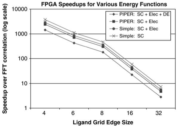
The docking codes generally handle the multiplicity of energy functions by executing multiple FFTs. Also, there is no advantage to having a small datatype and little advantage to having a small ligand. The FPGA-accelerated versions differ in three ways: (i) they execute the multiple functions simultaneously; (ii) the small datatype results in a more efficient configuration and thus more parallelism and higher performance; and (iii) the performance is inversely proportional to the number of elements in the ligand. Fig. 9 shows the speed-ups of the FPGA-accelerated versions of four combinations of energy functions. The series labelled ‘Simple’ represents the energy functions used in DOT and FTDock while the series labelled ‘PIPER’ represents the more complex PIPER versions of these functions. ‘DE’ refers to the use of four pairwise potential terms. As expected, the simpler the energy functions, the greater the speed-up.
Figure 9. Graph shows speed-up of the FPGA accelerator over a single core against ligand size for various energy function combinations.
Only the correlation task is evaluated
5.4.2 Performance of the correlation task for various technologies
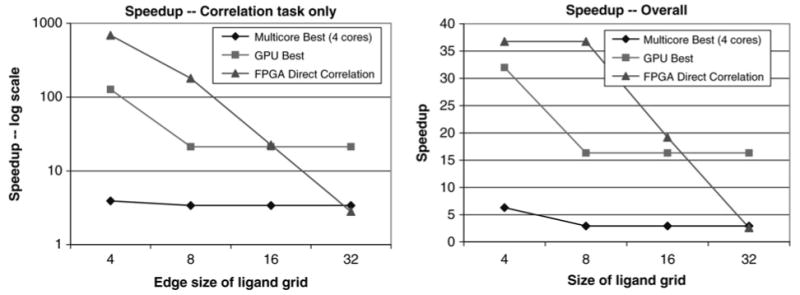
We measure the performance of the correlation task for the PIPER energy functions with four pairwise potential terms (left panel of Fig. 10). For the GPU, multicore, and single core, the FFT was faster than direct correlation for all ligand sizes but 43. The leftmost data points therefore use that method for all the technologies, including the single core reference. The crossover point for the FPGA version is 16 with respect to the GPU and about 30 with respect to a four core processor.
Figure 10. The left panel shows speed-up of the PIPER correlation task for various technologies The right panel shows end-to-end speed-up. Eighteen pairwise potential terms are used.
5.4.3 Performance of the entire application for various technologies
For reference we show PIPER run with 10 000 rotations and P = 18 (right panel of Fig. 10). The total run time on a single core is 27.8 h. When PIPER is used in production, jobs are executed in batch mode on 1 K node IBM BlueGene L.
When the entire application is run the speed-ups are reduced. The GPU performs filtering as a separate step, whereas on the FPGA it is pipelined with the correlation and so its latency hidden. This increases the crossover point slightly. For the FPGA, the limiting factor is the host overhead (about 200 ms per rotation) which dominates the execution time for ligand sizes ≤83.
6 Discussion
We have presented an FPGA-based accelerator for a sophisticated, current, production docking code. In the process, we created a novel addition to our 3D correlation structure to enable effective computation of complex correlations. This structure reduces FPGA component utilisation by 38–40%. We also added support for piecewise correlation to enable efficient computation with large ligands. The overall result for small-molecule docking is a multi-100-fold speed-up for the correlation, which accounts for 95.4% of the computation. Acceleration of another 2.3% using an existing filtering method brings the potential total acceleration up to 42× over a single core; of this we currently obtain 36×. Since we achieve a speed-up of 3.4× for a four core implementation, the chip-to-chip speed-up is 10.5×. Accelerating the remaining 2.3% is work in progress – using a previously developed method for charge-to-grid assignment [21] appears promising. For protein–protein docking, the GPU's efficient FFT makes it the clear choice.
An important question is what these results say about the relative merit of FPGAs, GPUs and multicore CPUs for rigid molecule docking and similar computations. With respect to operating frequency, that of multi-core processors is about twice that of high-end GPUs, and five times that of an FPGA's peak. For floating point performance, the GPU's peak is four times that of an FPGA's, and eight times that of a quadcore processor. A more important measure, however, is the performance achieved for production applications and why. Here an FPGA has better performance (for small molecules) because its configurability allows a match between application and hardware. Two aspects stand out. One is that the correlation elements in the FPGA are built to the precision available in the problem, which enables 512 fully pipelined processors. The other is that this correlation pipeline runs at over 90% capacity. In contrast, the quadcore CPU and the GPU execute their FFTs (using library functions as described) at 10% and 4% of peak, respectively.
For large molecules, FFT-based correlation dominates. The 3D FFTs of the GPU and the multicore are superior to any currently available on FPGAs. It may be possible, however, to construct a competitive 3D FFT for FPGAs. For example, the Altera 1D FFT IP core executes a 128 element FFT in 0.89 μs. Since a 3D correlation requires computing approximately 3N2 1D FFTs of length N, the ideal 3D implementation would take 43.75 ms. This core, however, occupies less than 10% of the Stratix-III EPSL340. If the entire chip could be used, then the latency would be reduced to less than 5 ms. Actual performance, however, depends on a number of factors: memory bandwidth, on-chip storage, and routing and control structures. For example, the 1D FFT requires a bandwidth of 576 MB/s. Although current FPGA-based systems support ten times that memory bandwidth, the interfaces may not have nearly the flexibility required. The lack of such an FPGA-based FFT is probably indicative of the relative challenge in programming FPGAs against GPUs and multicore.
The FPGA's place, for the time-being at least, is clearly with small molecule docking: a factor of 10× speed-up there means that many more drug alternatives can be examined. This advantage increases substantially for applications with simple energy functions (see Fig. 9). The highest impact, however, may be in applications that dock very small ligands. Such molecular fragments are used in computational solvent mapping for the critical application of determining druggable hot-spots within binding sites [25]. For this application, efficient charge assignment, would enable speed-ups of over 100×. Since our charge assignment algorithm depends on complex memory interleaving, the small ligand size is likely to simplify its implementation.
The significance of this work is in its potential to drastically increase the pace of discovery in both basic science and in drug discovery. As PIPER gets integrated into the popular online ClusPRO system [17], the impact of this work should increase further.
Acknowledgments
We thank members of the Structural Bioinformatics group at Boston University for their help in understanding the PIPER code. We also thank the anonymous reviewers for their many helpful corrections and suggestions. This work was supported in part by the NIH through award #R01-RR023168-01A1, and facilitated by donations from XtremeData, Inc., SGI, Altera Corporation, and Xilinx Corporation. Web: http://www.bu.edu/caadlab.
References
- 1.May M. Playstation cell speeds docking programs. Bio-IT World. 2008 July 14; [Google Scholar]
- 2.Servat H, Gonzalez-Alvarez C, Aguilar X, Cabrera-Benitez D, Jimenez-Gonzalez D. Drug design issues on the Cell BE. Proc 3rd Int Conf on High Performance and Embedded Architectures and Compilers. 2008:176–190. [Google Scholar]
- 3.Korb O. PhD thesis. University of Konstanz; 2008. Efficient ant colony optimization algorithms for structure- and ligand-based drug design. [Google Scholar]
- 4.Sukhwani B, Herbordt M. GPU acceleration of a production molecular docking code. Proc General Purpose Computation Using GPUs. 2009 [Google Scholar]
- 5.Kozakov D, Brenke R, Comeau S, Vajda S. PIPER: an FFT-based protein docking program with pairwise potentials. Proteins Struct Funct Genet. 2006;65:392–406. doi: 10.1002/prot.21117. [DOI] [PubMed] [Google Scholar]
- 6.Vancourt T, Gu Y, Herbordt M. FPGA acceleration of rigid molecule interactions. Proc IEEE Conf on Field Programmable Logic and Applications. 2004 [Google Scholar]
- 7.Vancourt T, Herbordt M. Rigid molecule docking: FPGA reconfiguration for alternative force laws. J Appl Signal Process. 2006;2006:1–10. [Google Scholar]
- 8.DeLano Scientific LLC. PyMOL Molecular Viewer. [accessed: 2 November 2009]; available: http://pymol.org.
- 9.Wriggers W, Milligan R, Mccammon JS. A package for docking crystal structures into low-resolution maps from electron microscopy. J Struct Biol. 1999;125:185–195. doi: 10.1006/jsbi.1998.4080. [DOI] [PubMed] [Google Scholar]
- 10.Gabb H, Jackson R, Sternberg M. Modelling protein docking using shape complementarity, electrostatics, and biochemical information. J Mol Biol. 1997;272:106–120. doi: 10.1006/jmbi.1997.1203. [DOI] [PubMed] [Google Scholar]
- 11.Chen R, Weng Z. A novel shape complementarity scoring function for protein–protein docking. Proteins, Struct Funct, Genet. 2003;51:397–408. doi: 10.1002/prot.10334. [DOI] [PubMed] [Google Scholar]
- 12.Ritchie D, Kemp G. Protein docking using spherical polar fourier correlations. Proteins Struct Funct Genet. 2000;39:178–194. [PubMed] [Google Scholar]
- 13.Vakser I, Matar O, Lam C. A systematic study of low-resolution recognition in protein–protein complexes. Proc Natl Acad Sci. 1999;96:8477–8482. doi: 10.1073/pnas.96.15.8477. [DOI] [PMC free article] [PubMed] [Google Scholar]
- 14.Teneyck L, Mandell J, Roberts V, Pique M. Surveying molecular interactions with dot. Proc Supercomputing '95. 1995 [Google Scholar]
- 15.Schneidman-Duhovny D, Inbar Y, Nussinov R, Wolfson H. PatchDock and SymmDock: servers for rigid and symmetric docking. Nucl Acids Res. 2005;33:W363–W367. doi: 10.1093/nar/gki481. [DOI] [PMC free article] [PubMed] [Google Scholar]
- 16.Friesner RA, Banks JL, Murphy RB, et al. Glide: A new approach for rapid, accurate docking and scoring.1. method and assessment of docking strategy. J Med Chem. 2004;47:1739–1749. doi: 10.1021/jm0306430. [DOI] [PubMed] [Google Scholar]
- 17.Comeau S, Gatchell D, Vajda S, Camacho C. ClusPro: an automated docking and discrimination method for the prediction of protein complexes. Bioinformatics. 2009;20(1):45–50. doi: 10.1093/bioinformatics/btg371. [DOI] [PubMed] [Google Scholar]
- 18.Tovchigrechko A, Vakser I. GRAMM-X public web server for protein-protein docking. Nucl Acids Res. 2006;34:W310–W314. doi: 10.1093/nar/gkl206. [DOI] [PMC free article] [PubMed] [Google Scholar]
- 19.Kuntz I, Blaney J, Oatley S, Langridge R, Ferrin T. A geometric approach to macromolecule-ligand interactions. J Mol Biol. 1982;161:269–288. doi: 10.1016/0022-2836(82)90153-x. [DOI] [PubMed] [Google Scholar]
- 20.Katchalski-Katzir E, Shariv I, Eisenstein M, Friesem A, Aflalo C, Vakser I. Molecular surface recognition: determination of geometric fit between proteins and their ligands by correlation techniques. Proc Natl Acad Sci. 1992;89:2195–2199. doi: 10.1073/pnas.89.6.2195. [DOI] [PMC free article] [PubMed] [Google Scholar]
- 21.Gu Y, Herbordt M. FPGA-based multigrid computations for molecular dynamics simulations. Proc IEEE Symp on Field Programmable Custom Computing Machines. 2007:117–126. [Google Scholar]
- 22.Swartzlander E. Systolic signal processing systems. Marcel Dekker, Inc.; 1987. [Google Scholar]
- 23.XtremeData, Inc. XD1000 Development System. [Accessed February 2009]; www.xtremedata.com.
- 24.FFTW Web Page. [accessed January 2009]; Available at www.fftw.org.
- 25.Landon M, Lancia D, Jr, Yu J, Thiel S, Vajda S. Identification of hot spots within druggable binding regions by computational solvent mapping of proteins. J Med Chem. 2007;50(6):1231–1240. doi: 10.1021/jm061134b. [DOI] [PubMed] [Google Scholar]


