Abstract
The existing Ni-yttria-stabilized zirconia anodes in solid oxide fuel cells (SOFCs) perform poorly in carbon-containing fuels because of coking and deactivation at desired operating temperatures. Here we report a new anode with nanostructured barium oxide/nickel (BaO/Ni) interfaces for low-cost SOFCs, demonstrating high power density and stability in C3H8, CO and gasified carbon fuels at 750°C. Synchrotron-based X-ray analyses and microscopy reveal that nanosized BaO islands grow on the Ni surface, creating numerous nanostructured BaO/Ni interfaces that readily adsorb water and facilitate water-mediated carbon removal reactions. Density functional theory calculations predict that the dissociated OH from H2O on BaO reacts with C on Ni near the BaO/Ni interface to produce CO and H species, which are then electrochemically oxidized at the triple-phase boundaries of the anode. This anode offers potential for ushering in a new generation of SOFCs for efficient, low-emission conversion of readily available fuels to electricity.
 Anodes composed of nickel/yttria-stabilized zirconia in solid oxide fuel cells are known to suffer from coking, which reduces their performance. Here, Yang and colleagues report a new barium oxide/nickel anode, which efficiently oxidizes fuel with minimum carbon buildup.
Solid oxide fuel cells (SOFCs) offer great prospects for the most efficient and cost-effective utilization of hydrocarbons, gasified coal and a wide variety of ample carbonaceous solids (for example, municipal solid waste and biomass)1. SOFCs powered by gasified coal are twice as efficient as current coal-fired power plants, potentially reducing CO2 emission by 50%. The critical technical barriers to efficient utilization of these fuels are the vulnerability to coking of the Ni-YSZ (yttria-stabilized zirconia) anodes by dehydrogenation of hydrocarbons and CO disproportionation at temperatures below 850 °C (ref. 2), where SOFCs become more competitive economically3,4.
For direct utilization of hydrocarbon fuels, a number of alternative anodes have been developed, including ceria-based anodes5,6,7, La0.75Sr0.25Cr0.5Mn0.5O3-δ (with a Ce0.8Gd0.2O2-δ interlayer)8, Sr2Mg1-xMnxMoO6-δ (0≤x≤1)9, doped (La,Sr)(Ti)O3 (refs 10, 11) and Ni-BaZr0.1Ce0.7Y0.2-xYbxO3-δ (Ni-BZCYYb)12. However, the application of these anodes to actual fuel cell systems is hindered by several critical issues: they are either too expensive to be economically viable (for example, using a noble metal such as Ru or Pd) or outright incompatible with the current YSZ-based SOFCs systems, which have evolved progressively in the past few decades, because of the limited physical, chemical and thermal compatibility of the alternative anodes with YSZ electrolyte during fabrication at high temperatures. For example, it was found that the Ni-BZCYYb anode readily reacts with YSZ at high temperatures, which results in the necessity of implementation of a buffer layer between them in order to avoid formation of electrically insulating phases. Solution infiltration of alternative anode materials into Ni-YSZ anodes has been explored, but showed some success only with utilization of CH4 (ref. 13). In addition, the anode modified by Ru-CeO2 catalyst achieved the highest reported peak power density of ~0.5 W cm−2 in C3H8 at 750 °C (ref. 7); however, it is still much lower than that for a typical H2-fueled SOFC operated at the same temperature (~1.0 W cm−2).
As an important intermediate in utilization of carbon-containing fuels7 and the dominant component of gasified carbon or coal14, CO has been widely studied in SOFCs under various fuel cell operating conditions15,16,17,18. At temperatures below 850 °C, CO or CO-rich fuel mixtures readily deactivate Ni-YSZ anodes because of carbon buildup16,17,18, and more so at lower temperatures, as predicted by Boudouard's equilibrium. For example, Jiang and Virkar16 found that at 800 °C a CO disproportionation reaction occurred on the Ni-YSZ anode when the partial pressure of CO was greater than 0.8 atm (1 atm fuel), although a reasonable power density was demonstrated at the initial stage. Accordingly, SOFCs running on gasified carbon or coal through CO2 gasification are often operated at 850 °C or higher to avoid coking and deactivation14,19. Although SOFCs powered by H2-rich syngas derived from steam gasification of carbon may be operated at lower temperatures, the required excess of water not only dilutes the fuel but also increases system complexity and cost because of the need for water management14. To date, no stable and desirable power output has been demonstrated by SOFCs with Ni-YSZ-based anodes in CO or gasified carbon through CO2 gasification below 850 °C. The search for alternative anodes for direct utilization of CO at intermediate temperatures has progressed slowly and the existing SOFCs powered by CO and gasified carbon or coal are still inadequate for practical applications14,18,19,20,21. For example, the cell with Pd-La0.8Sr0.2Cr0.5Mn0.5O3-δ-Ce0.48Zr0.48Y0.04O2-δ anode yielded ~0.45 W cm−2 at 800 °C in 50%CO–50%CO2 fuel21.
Here we report a new anode with nanostructured barium oxide/nickel (BaO/Ni) interfaces by vapour deposition of BaO into Ni-YSZ. In this process, BaO vapour reacts with the surfaces of NiO, producing a thin layer of NiO-BaO compounds on the NiO surface. On exposure to a fuel, the thin film of NiO-BaO compounds is reduced to nanosized BaO islands distributed on the Ni surface; a continuous BaO film would block the electron path in the anode. This nanostructured surface layer readily adsorbs water and has a vital role in facilitating carbon removal, making it possible to efficiently utilize higher-order hydrocarbon, CO and gasified carbon fuels without carbon buildup at relatively low temperatures. Unlike the above-mentioned alternative anode materials, the elemental composition of the new anode is very simple and contains no rare earth elements, which helps work towards true cost effectiveness. Moreover, BaO treatment can be readily incorporated into existing processes for fabrication of the state-of-the-art SOFCs based on YSZ electrolyte; it does not introduce additional processing steps, as vapour deposition is implemented during the firing of the buffer layer, and no known compatibility issues that often arise with the use of other alternative anode materials occur with the BaO.
Although BaO or other alkaline earth oxides have been used as promoters for reforming catalysts22,23, their application to anodes in SOFCs has resulted in fuel cells with low power densities24,25,26. As alkaline oxides are electronic insulators, their addition to a Ni-YSZ anode may degrade the electrocatalytic activity of the anode. For example, the introduction of CaO to Ni-YSZ by mechanical mixing and BaO to Ni-GDC by solution impregnation reduced fuel cell power outputs, achieving a peak power density of only ~0.30 W cm−2 at 750 °C in CH4 (refs 24,25,26). Although the performances in higher-order hydrocarbons have not been disclosed, it is reasonable to predict that the power output in C3H8 would be even lower stemming from inherently slower reaction kinetics7. The critical challenge lies in creating an anode surface composed of numerous nanostructured BaO/Ni interfaces that will promote the removal of carbon (a chemical process) on the exposed Ni surface but will not impede the charge transfer processes across the interfaces and along the surfaces (electrochemical processes) of the anode to achieve high-power output. In this study, a stable peak power density of 0.88 W cm−2 in dry C3H8 at 750 °C was obtained by creating nanostructured BaO/Ni interfaces in the anode.
Results
Characterization of BaO islands and BaO/Ni interface
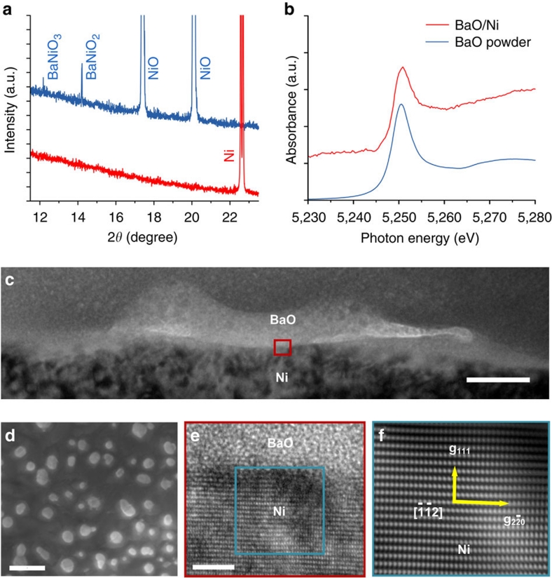
To characterize the detailed structure and composition of the surfaces in this new anode, we used synchrotron-based X-ray analyses because the nanostructured surface layers were very thin and undetectable using conventional X-ray analysis. Figure 1a shows typical grazing incidence angle X-ray diffraction patterns collected from the surface of a BaO/NiO sample before and after reduction in H2. Before reduction, the main phase was cubic polycrystalline NiO, but weak diffraction peaks related to BaNiO2 and BaNiO3 on the NiO surface were also observable, indicating the presence of these two phases in very low quantity. This is consistent with the known phases in the BaO–NiO system. After reduction in H2, however, only metallic Ni was detected. No diffraction peaks related to any compounds in the Ba–Ni–O system could be detected even with extended X-ray exposure, suggesting that any Ba-containing phases were lacking long-range order. Our Ba LIII-edge X-ray absorption near-edge structure analysis (Fig. 1b) showed that Ba was indeed still present on the Ni surface in compound form, not as Ba metal, implying the presence of BaO on the Ni surface.
Figure 1. Microanalysis of BaO nanoislands and BaO/Ni interfaces.
(a) Grazing incidence angle X-ray diffraction patterns of BaO/NiO samples before (blue curve) and after (red curve) reduction in hydrogen. These patterns were collected at X14A beamline of National Synchrotron Light Source (NSLS). The incident angle was 0.1° and the wavelength λ was 0.72838 Å. (b) Ba LIII-edge X-ray absorption near-edge structure (XANES) spectra of BaO powder and the BaO/Ni sample. The XANES spectra were collected at X18A beamline of NSLS using reflective detection mode. The Ba LIII-edge XANES spectrum of BaO/Ni was an average of 13 spectra. (c) Cross-sectional view (bright-field TEM image) of a BaO/Ni interface. Scale bar, 30 nm. (d) Top view (SEM image) of a BaO/Ni sample. Scale bar, 200 nm. (e) HRTEM image of the BaO/Ni interface. Scale bar, 2 nm. The [ ] zone axis of the Ni under the BaO island is along the viewing direction. (f) Fourier-filtered [
 ] zone axis image of the Ni under the BaO island.
To reveal the local microstructures and morphologies of the nanosized BaO islands and the BaO/Ni interfaces, we used electron microscopy and spectroscopy. A scanning electron microscope (SEM) examination revealed that BaO nanoislands were uniformly distributed on the Ni surface (Fig. 1d); the presence of Ba and O in the islands was confirmed by energy dispersive spectroscopy (EDS). The island sizes varied from a few nanometres to over 100 nm, and the distances between two neighbouring BaO islands were on the order of several tens of nanometres. A cross-sectional view (Fig. 1c) and a Z-contrast image (Supplementary Fig. S1a) of a BaO/Ni interface indicated that the thickness of the BaO island was up to ~30 nm. In addition, Z-contrast imaging coupled with simultaneous EDS (Supplementary Fig. S1b) was performed to confirm the presence of Ba and O in the island with a nanoprobe (full-width at half-maximum ~3 Å). A selected area electron diffraction pattern, taken from the BaO island on the Ni surface (Supplementary Fig. S2), consisted of characteristic Ni spots and a diffuse ring, which again suggests that the BaO island lacked long-range order. This is also consistent with the X-ray diffraction spectrum acquired from the same sample (Fig. 1a). A high-resolution transmission electron microscopy (HRTEM) image of the interface (Fig. 1e) clearly resolved the (1 1 1) and ( ) lattice fringes along the [
 ] zone axis of the Ni under the BaO island. It also revealed the amorphous appearance of the BaO island on the Ni surface. The Ni [
 ] zone-axis image and amorphous appearance of the BaO island are consistent with the selected area electron diffraction pattern (Supplementary Fig. S2). To highlight the zone-axis fringes of the underlying Ni grain, a Fourier-filtered image of the rectangular area marked in the image (Fig. 1e) is presented in Figure 1f. A solid sphere model of the face-centred cubic lattice structure of Ni viewed along the [
 ] direction is shown in Supplementary Figure S3, where correlation between the model and HRTEM imaging is illustrated.
Power output and durability of fuel cells in C3H8 fuel
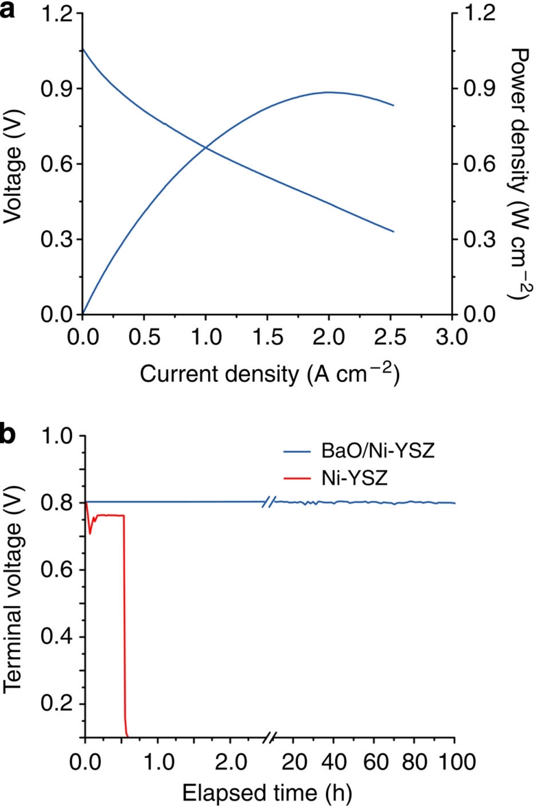
To examine the electrocatalytic activity of the anode with nanostructured BaO/Ni interfaces towards hydrocarbon fuels, we investigated the current–voltage characteristics and measured the corresponding power densities of fuel cells consisting of such an anode, a YSZ electrolyte, a Sm0.2Ce0.8O2-δ (SDC) buffer layer and a La0.6Sr0.4Co0.2Fe0.8O3-δ (LSCF) cathode operated with dry C3H8. Figure 2a shows a typical peak power density of ~0.88 W cm−2 at 750 °C when dry C3H8 was used as the fuel, which is much higher than ~0.5 W cm−2 at 750 °C reported for the latest SOFCs operated under similar conditions7. The power output is also higher than those reported in the recent literatures related to the alkaline oxide-modified anodes24,25,26, namely ~0.30 W cm−2 at 750 °C in CH4. Again, although the performances for these cells in C3H8 were not reported, they should be lower than the power densities in CH4 because of more carbon atoms7. Furthermore, the cell displayed stable power output for more than 100 h at a constant current density of 500 mA cm−2, suggesting that the carbon deposit was largely absent on the anode. In contrast, the performance of the fuel cell with a conventional Ni-YSZ anode, tested under identical operating conditions, dropped rapidly in dry C3H8, due primarily to carbon buildup and deactivation of the anode (Fig. 2b). Subsequent SEM inspection of the Ni-YSZ anodes with and without BaO/Ni interfaces showed that minimal carbon deposition occurred on the modified anode, whereas the heavy disintegration of Ni-YSZ anode induced by carbon deposits was developed during the course of fuel cell operation (Supplementary Fig. S4).
Figure 2. Performance of fuel cells with the new anode in dry C3H8.
(a) Typical current–voltage characteristics and the corresponding power densities measured at 750 °C for cells with a configuration of BaO/Ni-YSZ |YSZ| SDC/LSCF when dry C3H8 was used as the fuel and ambient air as the oxidant. (b) Terminal voltages measured at 750 °C as a function of time for the cells with and without BaO/Ni interfaces operated at a constant current density of 500 mA cm−2 with dry C3H8 as the fuel. Water was formed on the anode by electrochemical oxidation of dry C3H8.
Power output and durability of fuel cells in CO and gasified carbon fuels
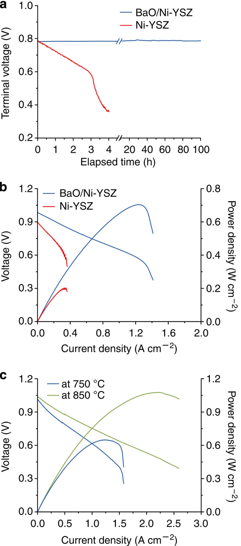
To inspect the behaviour of this new anode in CO and its tolerance to coking due to the CO disproportionation reaction, we fed CO fuel to test cells. Figure 3a shows the terminal voltage of a cell with such an anode operated at a constant current density of 500 mA cm−2 at 750 °C as a function of time when wet CO was used as the fuel, demonstrating a steady performance up to more than 100 h. This cell also displayed very stable open circuit voltage (OCV), indicating again that the presence of ~3 v% water is sufficient to avoid carbon buildup on the anode under OCV conditions. Furthermore, this fuel cell demonstrated a peak power density of ~0.70 W cm−2 at 750 °C in CO (Fig. 3b), which is lower than that in H2, indicating slower CO oxidation kinetics relative to H2 on the new anode. However, this power output represents the highest ever reported under similar testing conditions (Supplementary Table S1), suggesting that the new anode may facilitate carbon removal reactions and could efficiently convert CO to electricity. In contrast, a conventional Ni-YSZ anode was deactivated quickly in wet CO at 750 °C and the peak power density was only ~0.2 W cm−2 after 4 h of operation (Fig. 3b).
Figure 3. Fuel cell performance in CO and in gasified carbon.
(a) Terminal voltages measured at 750 °C as a function of time for the cells with and without BaO/Ni interfaces operated at a constant current density of 500 mA cm−2 with wet CO (with ~3 v% H2O) as the fuel. (b) Typical current–voltage characteristics and the corresponding power densities measured at 750 °C for cells with and without BaO/Ni interfaces (after 4 h operation) when wet CO was used as the fuel and ambient air as the oxidant. (c) Typical current–voltage characteristics and the corresponding power densities measured at 850 and 750 °C for cells with BaO/Ni interfaces when gasified carbon was used as the fuel and ambient air as the oxidant in a fluidized carbon bed-SOFC arrangement.
To evaluate the feasibility of using gasified solid carbonaceous fuels, we used a fluidized carbon bed-SOFC arrangement (Supplementary Fig. S5). Analysis of the effluent gas using mass spectrometry indicated that carbon was converted primarily to CO (~96%) with small amounts of H2, H2O, CO2 and CH4 through wet (~3 v% water vapour) CO2 gasification (Supplementary Fig. S6). The fuel cell with the new anode and gasified carbon as the fuel in this configuration demonstrated a peak power density of ~1.08 W cm−2 at 850 °C (Fig. 3c), about twice that of a cell with a conventional Ni-YSZ anode under the same conditions (~0.52 W cm−2) and the latest cell using gasified coal with CO2 gasification (~0.45 W cm−2 at 850 °C)14. More importantly, when the operating temperature was reduced to 750 °C, the fuel cell with the new anode still displayed a stable power output and reached a peak power density of ~0.65 W cm−2 (Fig. 3c). In contrast, a conventional Ni-YSZ anode cannot be stably operated in gasified carbon at this temperature, which is consistent with the observed behaviour of the same cell when CO was used as the fuel (Fig. 3a). Microanalyses of the BaO/Ni-YSZ anodes before and after operation in gasified carbon showed no observable microstructural change or carbon buildup (Supplementary Fig. S4). Furthermore, a fuel cell with a BaO/Ni-YSZ anode displayed stable operation in H2 for ~1,000 h (Supplementary Fig. S7), implying good stability of the anode under the operating conditions.
Evaluation of water uptake capability
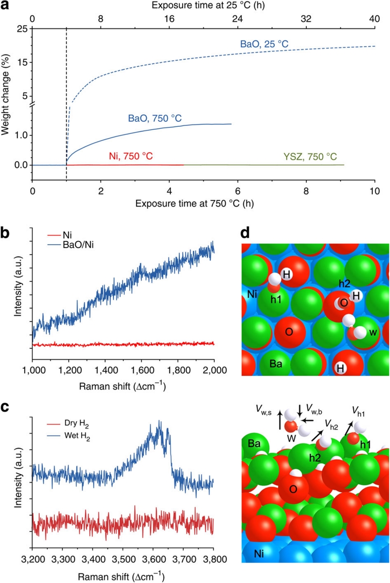
We used thermogravimetric analysis (TGA) and Raman spectroscopy to study the interactions between water vapour and the anode materials under different conditions. TGA traces for Ni and YSZ powder samples (Fig. 4a) showed little weight change as the gas was switched from dry to wet (3 v% water vapour) argon with 4 v% H2, implying that Ni-YSZ anodes hardly interact with water vapour at these temperatures. In contrast, drastic weight gains were observed for BaO powder samples upon exposure to the wet gas, implying that BaO strongly takes up water from the gas phase. This is consistent with our theoretical predictions that H2O dissociatively adsorbs on BaO27 (Supplementary Table S2, adsorption energy: −1.35 eV), but only weakly bonds to Ni28 and YSZ (Supplementary Table S2, adsorption energy: −0.32 and −0.54 eV, respectively). It is noted that the water uptake capacity of BaO decreased from ~20.0% at 25 °C to ~1.4% at 750 °C; however, the amount of water involved at 750 °C is still substantial. The water uptake behaviour is also confirmed by Raman spectroscopy (Fig. 4b,c). A peak near 1,600 cm−1, corresponding to the bending mode of water29, is observed on the Raman spectra collected from a BaO/Ni sample, but absent on that from a pure Ni exposed to wet H2. Further, the broad mode between 3,450 and 3,700 cm−1 on the spectrum from the BaO/Ni sample exposed to wet H2 indicates the presence of water with weak hydrogen bonds, which is likely on the surface of the sample30. Our density functional theory (DFT) calculations with a monolayer (ML) of H2O on a BaO/Ni surface support the Raman measurements that a H2O bending mode is at 1,594 cm−1, whereas two stretching modes of adsorbed OH species on BaO are at 3,368 and 3,716 cm−1, respectively (Fig. 4d). In contrast, these spectral features disappeared when the same sample was exposed to dry H2, further confirming the water uptake capability of the surface layers.
Figure 4. Assessment of water uptake capability.
(a) Typical thermogravimetric traces for Ni, YSZ and BaO powder samples in dry and wet argon with 4 v% H2 at 25 and 750 °C. (b) Raman spectra recorded from BaO/Ni and pure Ni samples in wet H2 (with ~3 v% H2O) atmosphere at room temperature. (c) Raman spectra collected from BaO/Ni samples in dry and wet H2 (with ~3 v% H2O) atmospheres at room temperature. (d) Top and side views for the interaction of H2O on two-layer BaO deposited on p(3×3) Ni(1 1 1) containing six Ba and six O atoms. 'w', 'h1' and 'h2' represent molecularly adsorbed H2O and dissociated hydroxyl species, whereas vw,b, vh1 and vh2 are the vibration modes of a H2O bending and two OH stretchings (1,594, 3,716 and 3,368 cm−1), respectively. Large balls in Brandeis blue, green and red are Ni, Ba and O of BaO, respectively, whereas small balls in red and white are O from H2O and H, respectively.
DFT prediction of water-mediated carbon removal
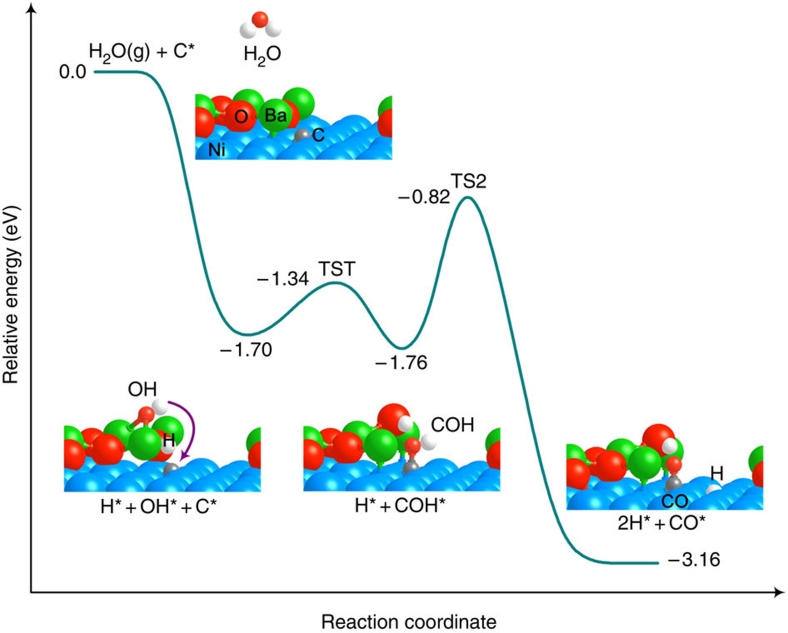
To gain insight into the mechanism of coking tolerance of this new anode, we constructed models for DFT calculations using the Vienna ab initio simulation package31,32. As the Ni(1 1 1) surface represents the energetically most stable facet of Ni (Fig. 1f), we constructed a BaO/Ni(1 1 1) surface containing a small BaO chain (three Ba and three O atoms) over a three-layer p(3×5) Ni substrate33 (Fig. 5). Our DFT calculations using this BaO/Ni(1 1 1) model show that the adsorption of CO on BaO (adsorption energy: −0.78 eV; adsorption site: O atop) is much weaker than that on Ni (adsorption energy: −2.60 eV; adsorption site: Ni hexagonal close-packed hollow). Given these energies, under the high temperature of the reaction, it is unlikely that the water–gas shift reaction would be effective on BaO. On the other hand, carbon formation due to dehydrogenation of hydrocarbons or CO disproportionation reaction occurs readily on Ni catalysts34, resulting in chemically adsorbed carbon on Ni surfaces. Thus, we examined the mechanism for the removal of carbon near the BaO-like chains on Ni(1 1 1). As schematically shown in Figure 5, energetically the most plausible reaction pathway can be described as follows: H2O strongly adsorbs on the BaO site of BaO/Ni(1 1 1), which releases energy of −1.70 eV and leads to a barrierless O–H bond cleavage and hydroxylated BaO. In contrast, H2O weakly adsorbs on the Ni site and a reaction barrier of 1.05 eV has to be overcome to break the O–H bond. Similar to a previous study33, our calculations show that H2O dissociation is more favourable near the oxide-metal interface region than on the oxide and metal surfaces. The dissociated OH then reacts with an adsorbed C on the Ni surface via TS1 (transition state 1, reaction barrier: 0.36 eV) to form an intermediate COH, which is subsequently dissociated to CO and H via TS2 (reaction barrier: 0.94 eV). Finally, CO and H diffuse to a triple-phase boundary (TPB), where they are electrochemically oxidized (combined with O2−) to CO2 and H2O, respectively.
Figure 5. DFT prediction of energy profile.
The energies for removal of chemisorbed carbon species on BaO/Ni(1 1 1) are relative to gas-phase H2O and an adsorbed carbon species on BaO/Ni(1 1 1). '* denotes an adsorbed species on the surface. TS, transition state.
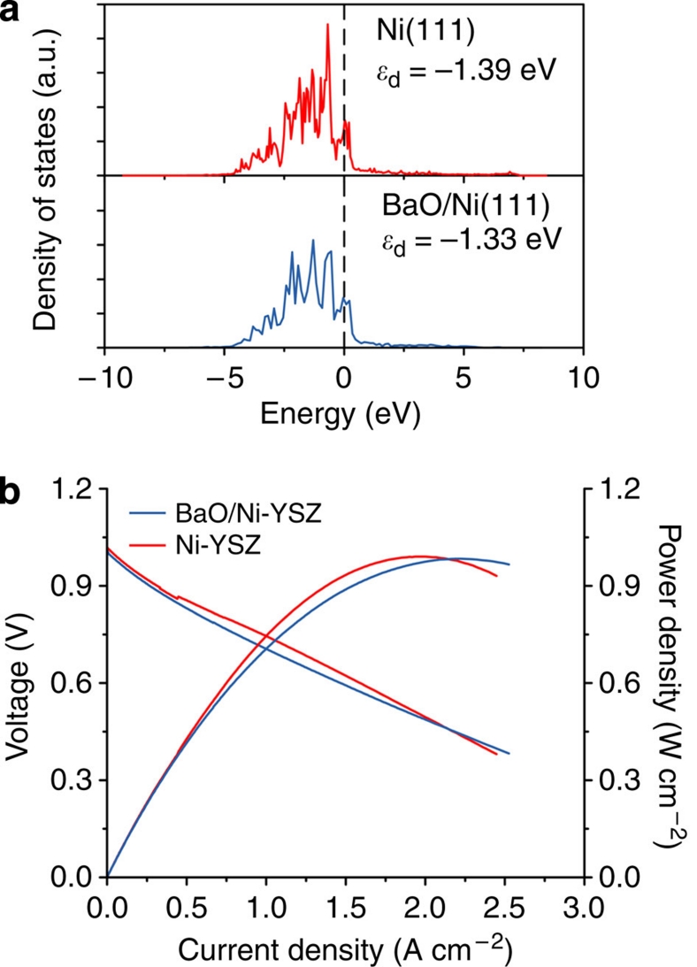
In addition, our DFT calculations predict that the electronic properties (for example, the d-band centre) of Ni are not adversely affected by the deposition of the BaO in the model with a small BaO chain (three Ba and three O atoms) over a three-layer p(3×5) Ni substrate; the d-band centre of pure Ni (Ed) is very close to that of BaO/Ni, indicating that the BaO deposition has little effect on the electronic properties of Ni (Fig. 6a). This is further corroborated by experimental results; the power output of a fuel cell with this new anode in H2 is similar to those of a fuel cell with a conventional Ni-YSZ anode under the same testing conditions (Fig. 6b), suggesting that the nanoislands of BaO on the Ni surface do not hinder the charge transfer processes on the anode. It is noted, however, that the power output of the fuel cell with the new anode in H2 is higher than that when CO was used as the fuel (Fig. 3c). The discrepancy in performance could be attributed primarily to the slower CO oxidation kinetics.
Figure 6. Effect of BaO nanoislands on electronic properties of Ni anode.
(a) Projected density of states of Ni(1 1 1) and BaO/Ni(1 1 1) using DFT. The vertical dashed line is the Fermi level. The values in the figure are predicted d-band centres based on seven bare Ni atoms on the topmost Ni layer. (b) Typical current–voltage characteristics and the corresponding power densities measured at 750 °C for cells with configurations of BaO/Ni-YSZ|YSZ| SDC/LSCF and Ni-YSZ |YSZ|SDC/LSCF when dry hydrogen was used as the fuel and ambient air as the oxidant.
Discussion
As carbon forms much more readily on Ni than on YSZ35, BaO/Ni interfaces are more important than BaO/YSZ interfaces for carbon removal. The synchrotron-based X-ray analyses and electron microscopy have shown that BaO nanoislands were formed on Ni by vapour deposition and subsequent reduction, creating a thin, nanostructured surface layer consisting of numerous BaO/Ni interfaces. Unlike the carbon-tolerant Sn-Ni catalyst36 that requires full coverage of Ni by surface alloy to be effective, alkaline oxides37 were reported to effectively diminish the tendency of carbon buildup by partial coverage of Ni surfaces.
Cells with our new anode have shown superior power density and stability in C3H8, CO and gasified carbon fuels versus conventional Ni-YSZ anodes. Although Ni-YSZ anode can indeed be operated in CO and gasified carbon at temperatures higher than 850 °C, which is a less severe condition for carbon buildup on Ni due to a less predominant CO disproportionation reaction at higher temperatures, the fuel cell without BaO treatment yielded much lower power density than the fuel cell with nanostructured BaO/Ni interfaces (Fig. 3c). In addition, as the operating temperature is lowered, much less expensive materials may be used for cell components to considerably reduce the cost while improving the reliability and operational life of fuel cells, making them more commercially viable. The demonstrated coking tolerance and high performance in CO at lower temperatures therefore advances the possibility for efficient conversion of gasified coal or other carbonaceous solid fuels to electricity.
Although it is also possible to avoid coking on conventional Ni-YSZ anodes by gasification of carbon with sufficient H2O and CO2 to produce H2-rich syngas or CO2-rich gas, the amounts of H2O and CO2 required are often excessive, greatly diluting the fuel and lowering energy efficiency in addition to increasing system complexity and cost because the need for H2O/CO2 management38. In this study, wet (~3 v% water vapour) CO2 was used for carbon gasification to produce a fuel gas containing ~96% CO and ~1% H2. The high performance of the new anode with this fuel composition cannot be attributed to the oxidation of H2, as the cells with a conventional Ni-YSZ anode showed much lower power output under the same conditions. This is further corroborated by the findings of other studies on button-type cells with a Ni-YSZ anode (for low fuel utilization like ours) in a fuel mixture of H2 and CO16: the anodic polarization was much larger when the CO content was considerably higher (>55%) in the fuel mixture due primarily to sluggish CO oxidation and a slow shift reaction15,16, whereas the difference in performance was relatively small as the H2 content was increased from ~45 to 100% H2. The demonstrated high-power output and coking tolerance in gasified carbon without excess H2O/CO2 at intermediate temperatures represents a critical step towards an economically feasible fuel cell for utilization of gasified coal or carbonaceous solid fuels.
With C3H8 fuel, no H2O or CO2 was introduced into the new anode as the water was produced on the anode from fuel cell operation. The observed stable power outputs of the cell with this new anode in dry C3H8 at a current density of 500 mA cm−2 is attributed primarily to the formed water on the anode, which promoted carbon removal near the BaO/Ni interfaces. Therefore, the high performance and tolerance to coking of the electrode at lower temperatures is attributed to the nanostructured BaO/Ni interfaces that do not block the electrochemical processes on the anode while promoting carbon removal in the presence of a small amount of water, which was introduced either by electrochemical oxidation of C3H8 when dry C3H8 was used as the fuel or by humidification when CO was used as the fuel.
The TGA and Raman analyses discussed above further validated the hypothesis that the observed electrocatalytic properties of the new anode are associated with their unique capability to adsorb and/or absorb water vapour under the operating conditions. From these analyses, it is clear that the water associated with the BaO/Ni interfaces have a vital role in enhancing the tolerance to coking and deactivation at intermediate temperatures. These findings are in turn supported by the DFT calculations, which revealed that the water-mediated carbon removal reactions occur more favourably at the BaO/Ni interfaces. The catalyst works synergistically: the dissociation of water takes place on the BaO, the carbon formation occurs on the Ni sites of BaO/Ni and all subsequent steps occur at or near the BaO/Ni interfaces. Our results imply that the high performance and coking tolerance of this new anode relies heavily on the direct participation of the BaO/Ni interfaces.
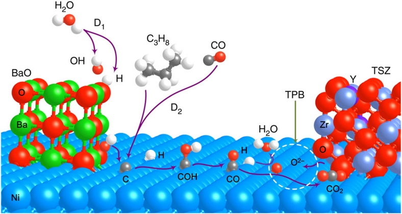
To briefly expand upon the discussion of these calculations, according to our findings, the rate-limiting step during the COH process is the O–H bond cleavage of COH. Thus, the use of new materials with BaO that accelerate the COH dissociation to CO and H may further enhance coking tolerance. On the basis of this analysis, the most probable elementary processes on the anode with nanostructured BaO/Ni interfaces are schematically illustrated in Figure 7 and summarized as follows.
| 1 |
| 2 |
| 3 |
| 4 |
| 5 |
| 6 |
Figure 7. Proposed mechanism for water-mediated carbon removal on the anode with BaO/Ni interfaces.
Large balls in Brandeis blue, green, red, blue grey and purple are Ni, Ba, O of BaO or YSZ, Zr and Y, respectively, whereas small balls in red, white and grey are O from H2O, H and C, respectively. D1 is the dissociative adsorption of H2O, whereas D2 is the dehydrogenation of hydrocarbons or the CO disproportionation reaction.
In summary, a new anode with nanostructured BaO/Ni interfaces was fabricated by vapour deposition and subsequent reduction. These interfaces do not impede the charge transfer on the anode while promoting a water-mediated carbon removal process and enhancing its resistance to carbon buildup and deactivation under fuel cell operating conditions. Although the demonstrated higher performances and coking tolerance of this anode at lower temperatures represent a vital step towards a cost-effective fuel cell for direct conversion of hydrocarbons and gasified carbonaceous solid fuels to electricity, the impact of other contaminants on the performance of this anode is yet to be investigated. It is possible, however, that many contaminants may be effectively removed through proper cleaning, an approach feasible for stationary power generation and preferred for minimizing environmental impact.
Methods
Fabrication of fuel cells
The button-type fuel cells with a configuration of Ni-YSZ |YSZ| SDC/LSCF were fabricated in steps described as follows. First, an anode support with mixed NiO (Sigma-Aldrich) and YSZ powders (TOSOH; weight ratio of 55:45) was fabricated by tape casting (~0.6 mm thick and 13 mm in diameter), followed by pre-firing at 800 °C for 2 h. Second, a thin layer of YSZ (~15 μm) was deposited on the anode support by a solution coating process followed by co-firing at 1,400 °C for 5 h. Third, a Sm0.2Ce0.8O2-δ (SDC, synthesized by a chemical co-precipitation process) buffer layer (~3 μm) was screen-painted on YSZ surface and fired at 1,200 °C for 2 h. Fourth, an LSCF (Fuel Cell Materials) slurry was screen printed onto the top of the SDC layer and fired at 1,050 °C for 2 h to form a porous cathode (~30 μm thick) with an active area of 0.28 cm2. BaO was introduced into the NiO-YSZ structure by evaporation deposition during the firing of the SDC buffer layer. To accomplish this, ~30 mg BaO powder (Sigma-Aldrich) was placed underneath a co-fired NiO-YSZ|YSZ bilayer with the anode facing the BaO powder (but without physical contact) and the top surface of YSZ covered by a green SDC buffer layer; they were then fired at 1,200 °C for 2 h. During this process, BaO vapour reacts with NiO, producing a thin layer of NiO-BaO compounds on the NiO surface. On exposure to a fuel, the thin film of NiO-BaO compounds is reduced to BaO nanoislands distributed on the Ni surface, creating nanostructured BaO/Ni interfaces.
Electrochemical measurements
First, Ag/Pt paste and Ag/Pt wire were applied to both the anode and cathode sides for current collection. Further, each button cell was sealed on an alumina tube and heated to 750 °C in ambient air, followed by reduction of anode in H2. For evaluation of performance based on wet CO or dry C3H8 fuels, the cells were conditioned in H2 to enter steady state before the fuel was switched to wet CO or dry C3H8. Both flow rates were 10 ml min−1. The wet CO was passed through a water bubbler at room temperature, yielding ~3 v% water vapour. For carbon fuel, we integrated a fluidized bed gasifier with a fuel cell, as schematically shown in Supplementary Figure S5a. K2CO3 (Sigma-Aldrich) was used as a catalyst to enhance the gasification rate and reduce the reaction temperature. The catalyst loading was ~0.0024 mol K+ per gram of activated C. First, 0.884 g K2CO3 was dispersed into 50 ml deionized water. Second, 5 g activated carbon (Norit DLC Supra 30, Norit) was added to the solution under stirring for 24 h, followed by drying in an oven at 80 °C. Third, 0.4 g carbon mixture was placed into the testing fixtures such that intimate contact with the anode surface was achieved. When the operating temperature was reached, wet CO2 (~3 v% H2O) was fed into the system after reduction of the anode in H2. All standard electrochemical experiments were performed using a Solartron 1286 electrochemical interface and a Solartron 1255 HF frequency response analyser (Solartron). The long-term electrochemical performances of test cells were acquired using an Arbin fuel cell testing system (MSTAT).
Other characterizations
To characterize the structure, composition and morphology of the BaO islands and BaO/Ni interfaces, we used synchrotron-enabled X-ray diffraction and absorption spectroscopy, as well as advanced electron microscopy and spectroscopy (scanning transmission electron microscopy (STEM), HRTEM, SEM and EDS). First, dense NiO pellets were fabricated by dry pressing and sintering at 1,450 °C for 5 h. Thereafter, the surface of the NiO pellet was exposed to BaO vapour at 1,200 °C for 2 h, as described earlier for fabrication of full cell anodes. The BaO/NiO sample was then reduced in dry H2 at 750 °C for 1 h, again, similar to the procedures used for fuel cell preparation and testing. The surface of BaO/NiO pellets after reduction was first analysed with a LEO 1530 field emission SEM/EDS operated at 15 kV. The TEM samples were prepared with the method of focused ion beam (FIB) in situ lift-out. A thin layer containing tungsten was applied on the BaO/Ni surface before FIB lift-out, and thus would form a strong mass contrast with the BaO island. The FIB was carried out with a Hitachi NB5000 FIB-SEM (Hitachi) operated at 40 kV. The cut sample was examined in an HF3300 TEM/STEM/EDS equipped with a field emission gun and operated at 300 kV. STEM and EDS were conducted with an electron probe of a size of ~3 Å. The grazing incidence angle thin-film X-ray diffraction analysis was carried out at beamline X14A of the National Synchrotron Light Source at Brookhaven National Laboratory using a six-circle Huber diffractometer and a Si strip detector. Barium LIII-edge X-ray absorption near-edge structure data were collected at beamline X18A of the National Synchrotron Light Source using the fluorescence detection mode, and the data were processed using the Athena and Artemis software packages. TGA was performed using a TA Q600 DSC-TGA system. Before comparing the water uptake ability, powders of Ni, BaO and YSZ were first heated to 1,000 °C and held for 4 h under dry argon with 4 v% H2 to remove water and possible surface carbon dioxide. As for the Raman measurements, the BaO/NiO and pure NiO samples were reduced in dry H2 gas at 500 °C for 2 h using a custom-made environmental chamber. Raman spectra were then obtained in dry/wet H2 using a Renishaw 1000 Raman spectromicroscopy system with a 514-nm excitation wavelength. The spot size was ~5 μm in diameter.
Computational methods
DFT calculations with the projector-augmented wave39 method were carried out using the Vienna ab initio simulation package31,32. The spin-polarization calculation was applied because of the magnetic properties of Ni. Although the generalized gradient approximation with the Perdew-Wang exchange-correlation functional40 was used, the kinetic energy cutoff for a plane-wave basis set was 400 eV. To allow convergence to 0.01 eV of the total electronic energy, the Brillouin zone was sampled with the (3×3×3) and (3×3×1) Monkhorst-Pack mesh41 k-points for bulk and surface calculations. For the two-dimensional (2D) slab model calculations, surfaces were separated by a vacuum space of 15 Å in the direction perpendicular to the surface. The climbing image-nudged elastic band method42,43 was applied to locate transition states, and potential energy surfaces were constructed accordingly. The adsorption energy (Eads) reported in the study was calculated as follows:
where E[adsorbate-surface], E[surface] and E[adsorbate] are the predicted electronic energies for an adsorbed species on a surface, a bare surface and a gas-phase species such as H2O.
Author contributions
M.L.L. and L.Y. conceived the project and designed the experiments. L.Y. prepared and characterized electrolytes, electrodes and fuel cells under a variety of conditions. L.Y. and K.B. studied TGA and Raman measurements. Y.C. and P.L. carried out DFT calculations. W.Q. performed electron microscopy analyses. H.C., J.B. and T.A.T. performed synchrotron-based X-ray analysis. M.F.L. helped with preparation of button cells.
Additional information
How to cite this article: Yang, L. et al. Promotion of water-mediated carbon removal by nanostructured barium oxide/nickel interfaces in solid oxide fuel cells. Nat. Commun. 2:357 doi: 10.1038/ncomms1359 (2011).
Supplementary Material
Supplementary Figures S1-S7, Supplementary Tables S1-S2, and Supplementary References.
Acknowledgments
This material is based on work supported as part of the HeteroFoaM Center, an Energy Frontier Research Center funded by the US Department of Energy (DOE), Office of Science, Office of Basic Energy Sciences (BES) under Award Number DE-SC0001061. The authors acknowledge the use of the SHaRE User Facility at Oak Ridge National Laboratory (ORNL, sponsored by the Scientific User Facilities Division, US-DOE-BES) and the X14A beamline at Brookhaven National Laboratory (BNL, partially sponsored by the US-DOE-EERE, Vehicle Technologies Program, through the HTML User Program at ORNL). The DFT calculations were undertaken at BNL (supported by the US-DOE-BES under Contract No. DE-AC02-98CH10886) using the computational facilities at the National Energy Research Scientific Computing (NERSC) Center and at BNL's Center for Functional Nanomaterials (CFN). The authors acknowledge partial support of the WCU program at UNIST and US National Science Foundation (under Grant No. MRI-0722730), Dr Karren More and Ms Dorothy Coffey of SHaRE at ORNL for TEM instrumentation support, and Professor M.C. Lin for CPU time.
References
- Singhal S. C. Advances in solid oxide fuel cell technology. Solid State Ionics 135, 305–313 (2000). [Google Scholar]
- Atkinson A. et al. Advanced anodes for high-temperature fuel cells. Nat. Mater. 3, 17–27 (2004). [DOI] [PubMed] [Google Scholar]
- la O' G. J. et al. Catalytic activity enhancement for oxygen reduction on epitaxial perovskite thin films for solid-oxide fuel cells. Angew. Chem. Int. Ed. 49, 5344–5347 (2010). [DOI] [PubMed] [Google Scholar]
- Hibino T. et al. A low-operating-temperature solid oxide fuel cell in hydrocarbon-air mixtures. Science 288, 2031–2033 (2000). [DOI] [PubMed] [Google Scholar]
- Murray E. P., Tsai T. & Barnett S. A. A direct-methane fuel cell with a ceria-based anode. Nature 400, 649–651 (1999). [Google Scholar]
- Park S. D., Vohs J. M. & Gorte R. J. Direct oxidation of hydrocarbons in a solid-oxide fuel cell. Nature 404, 265–267 (2000). [DOI] [PubMed] [Google Scholar]
- Zhan Z. L. & Barnett S. A. Use of a catalyst layer for propane partial oxidation in solid oxide fuel cells. Solid State Ionics 176, 871–879 (2005). [Google Scholar]
- Tao S. W. & Irvine J. T. S. A redox-stable efficient anode for solid-oxide fuel cells. Nat. Mater. 2, 320–323 (2003). [DOI] [PubMed] [Google Scholar]
- Huang Y. H., Dass R. I., Xing Z. L. & Goodenough J. B. Double perovskites as anode materials for solid-oxide fuel cells. Science 312, 254–257 (2006). [DOI] [PubMed] [Google Scholar]
- Ruiz-Morales J. C. et al. Disruption of extended defects in solid oxide fuel cell anodes for methane oxidation. Nature 439, 568–571 (2006). [DOI] [PubMed] [Google Scholar]
- Marina O. A., Canfield N. L. & Stevenson J. W. Thermal, electrical, and electrocatalytical properties of lanthanum-doped strontium titanate. Solid State Ionics 149, 21–28 (2002). [Google Scholar]
- Yang L. et al. Enhanced sulfur and coking tolerance of a mixed ion conductor for SOFCs: BaZr0.1Ce0.7Y0.2-xYbxO3-δ. Science 326, 126–129 (2009). [DOI] [PubMed] [Google Scholar]
- Jin Y. C., Yasutake H., Yamahara K. & Ihara M. Suppressed carbon deposition behavior in nickel/yittria-stablized zirconia anode with SrZr0.95Y0.05O3-δ in dry methane fuel. J. Electrochem. Soc. 157, B130–B134 (2010). [Google Scholar]
- Gür T. M., Homel M. & Virkar A. V. High performance solid oxide fuel cell operating on dry gasified coal. J. Power Sources 195, 1085–1090 (2010). [Google Scholar]
- Matsuzaki Y. & Yasuda I. Electrochemical oxidation of H2 and CO in a H2-H2O-CO-CO2 system at the interface of a Ni-YSZ cermet electrode and YSZ electrolyte. J. Electrochem. Soc. 147, 1630–1635 (2000). [Google Scholar]
- Jiang Y. & Virkar A. V. Fuel composition and diluent effect on gas transport and performance of anode-supported SOFCs. J. Electrochem. Soc. 150, A942–A951 (2003). [Google Scholar]
- Offer G. J. & Brandon N. P. The effect of current density and temperature on the degradation of nickel cermet electrodes by carbon monoxide in solid oxide fuel cells. Chem. Eng. Sci. 64, 2291–2300 (2009). [Google Scholar]
- Su C. et al. Assessment of nickel cermets and La0.8Sr0.2Sc0.2Mn0.8O3 as solid-oxide fuel cell anodes operating on carbon monoxide fuel. J. Power Sources 195, 1333–1343 (2010). [Google Scholar]
- Wu Y. Z., Su C., Zhang C. M., Ran R. & Shao Z. P. A new carbon fuel cell with high power output by integrating with in situ catalytic reverse Boudouard reaction. Electrochem. Commun. 11, 1265–1268 (2009). [Google Scholar]
- Costa-Nunes O., Gorte R. J. & Vohs J. M. Comparison of the performance of Cu-CeO2-YSZ and Ni-YSZ composite SOFC anodes with H2, CO, and syngas. J. Power Sources 141, 241–249 (2005). [Google Scholar]
- Bidrawn F. et al. Efficient reduction of CO2 in a solid oxide electrolyzer. Electrochem. Solid-State Lett. 11, B167–B170 (2008). [Google Scholar]
- York A. P. E., Xiao T. C., Green M. L. H. & Claridge J. B. Methane oxyforming for synthesis gas production. Catal. Rev. 49, 511–560 (2007). [Google Scholar]
- Tomishige K., Chen Y. G. & Fujimoto K. Studies on carbon deposition in CO2 reforming of CH4 over nickel-magnesia solid solution catalysts. J. Catal. 181, 91–103 (1999). [Google Scholar]
- Takeguchi T. et al. Study on steam reforming of CH4 and C2 hydrocarbons and carbon deposition on Ni-YSZ cermets. J. Power Sources 112, 588–595 (2002). [Google Scholar]
- La Rosa D. et al. Mitigation of carbon deposits formation in intermediate temperature solid oxide fuel cells fed with dry methane by anode doping with barium. J. Power Sourc. 193, 160–164 (2009). [Google Scholar]
- Asamoto M., Miyake S., Sugihara K. & Yahiro H. Improvement of Ni/SDC anode by alkaline earth metal oxide addition for direct methane-solid oxide fuel cells. Electrochem. Commun. 11, 1508–1511 (2009). [Google Scholar]
- Mei D. Density functional theory study of surface carbonate formation on BaO(001). J. Phys. Chem. C 114, 1867–1874 (2010). [Google Scholar]
- Phatak A. A., Delgass W. N., Ribeiro F. H. & Schneider W. F. Density functional theory comparison of water dissociation steps on Cu, Au, Ni, Pd, and Pt. J. Phys. Chem. C 113, 7269–7276 (2009). [Google Scholar]
- Lutz H. D. Bonding and structure of water-molecuels in solid hydrates—correlation of spectroscopic and structural data. Struct. Bond. 69, 97–125 (1988). [Google Scholar]
- Anedda A., Carbonaro C. M., Clemente F., Corpino R. & Ricci P. C. Raman investigation of surface OH-species in porous silica. J. Phys. Chem. B 107, 13661–13664 (2003). [Google Scholar]
- Kresse G. & Furthmüller J. Efficient iterative schemes for ab initio total-energy calculations using a plane-wave basis set. Phys. Rev. B 54, 11169–11186 (1996). [DOI] [PubMed] [Google Scholar]
- Kresse G. & Hafner J. Ab initio molecular dynamics for liquid metals. Phys. Rev. B 47, 558–561 (1993). [DOI] [PubMed] [Google Scholar]
- Rodriguez J. A. et al. Activity of CeOx and TiOx nanoparticles grown on Au(111) in the water-gas shift reaction. Science 318, 1757–1760 (2007). [DOI] [PubMed] [Google Scholar]
- Shishkin M. & Ziegler T. Oxidation of H2, CH4, and CO molecules at the interface between nickel and yttria-stablized zirconia: a theoretical study based on DFT. J. Phys. Chem. C 113, 21667–21678 (2009). [Google Scholar]
- Wei J. M. & Iglesia E. Isotopic and kinetic assessment of the mechanism of reactions of CH4 with CO2 or H2O to form synthesis gas and carbon on nickel catalysts. J. Catal. 224, 370–383 (2004). [Google Scholar]
- Nikolla E., Schwank J. & Linic S. Promotion of the long-term stability of reforming Ni catalysts by surface alloying. J. Catal. 250, 85–93 (2007). [Google Scholar]
- Bengaard H. S. et al. Chemisorption of methane on Ni(100) and Ni(111) surfaces with preadsorbed potassium. J. Catal. 187, 238–244 (1999). [Google Scholar]
- Ahmed K. & Foger K. Kinetics of internal steam reforming of methane on Ni/YSZ-based anodes for solid oxide fuel cells. Catal. Today 63, 479–487 (2000). [Google Scholar]
- Blöchl P. E. Projector augmented-wave method. Phys. Rev. B 50, 17953–17979 (1994). [DOI] [PubMed] [Google Scholar]
- Perdew J. P., Burke K. & Ernzerhof M. Generalized gradient approximation made simple. Phys. Rev. Lett. 77, 3865–3868 (1996). [DOI] [PubMed] [Google Scholar]
- Monkhorst H. J. & Pack J. D. Special points for Brillouin-zone integrations. Phys. Rev. B 13, 5188–5192 (1976). [Google Scholar]
- Henkelman G. & Jonsson H. Improved tangent estimate in the nudged elastic band method for finding minimum energy paths and saddle points. J. Chem. Phys. 113, 9978–9985 (2000). [Google Scholar]
- Henkelman G., Uberuaga B. P. & Jonsson H. A climbing image nudged elastic band method for finding saddle points and minimum energy paths. J. Chem. Phys. 113, 9901–9904 (2000). [Google Scholar]
Associated Data
This section collects any data citations, data availability statements, or supplementary materials included in this article.
Supplementary Materials
Supplementary Figures S1-S7, Supplementary Tables S1-S2, and Supplementary References.


