Abstract
We have developed a multichannel electrogmyography sensor system capable of receiving and processing signals from up to 32 implanted myoelectric sensors (IMES). The appeal of implanted sensors for myoelectric control is that electromyography (EMG) signals can be measured at their source providing relatively cross-talk-free signals that can be treated as independent control sites. An external telemetry controller receives telemetry sent over a transcutaneous magnetic link by the implanted electrodes. The same link provides power and commands to the implanted electrodes. Wireless telemetry of EMG signals from sensors implanted in the residual musculature eliminates the problems associated with percutaneous wires, such as infection, breakage, and marsupialization. Each implantable sensor consists of a custom-designed application-specified integrated circuit that is packaged into a bio-compatible RF BION capsule from the Alfred E. Mann Foundation. Implants are designed for permanent long-term implantation with no servicing requirements. We have a fully operational system. The system has been tested in animals. Implants have been chronically implanted in the legs of three cats and are still completely operational four months after implantation.
Keywords: Implanted device, myoelectric, prosthesis control, wireless telemetry
I. Introduction
Persons with recent hand amputations expect modern hand prostheses to function like intact hands. Unfortunately, current state-of-the-art electric prosthetic hands are generally single-DOF (opening and closing) devices that function and are controlled very differently from the natural hand. Prosthetic arms that allow multi-DOF movements require sequential control of these from multiple motions, using locking mechanisms and/or special switch signals to change control from one DOF to the next. This type of control is slow and counterintuitive. Consequently, because most devices fail to meet users' expectations, they tend to be underutilized or rejected [1], [2]. For persons with recent hand amputations “Every advancement in limb prosthetics is compared against re-creation of the physiological limb and the experience of the artificial limb. Although many people use prostheses and, in this way, accept the state-of-the-art, they are generally not satisfied with it. It is the nature of the work that prosthetics research is driven by dissatisfaction.” (personal communication).
A. EMG Use in Prosthesis Control
Consideration of both current and experimental control approaches drove the system requirements for our implantable myoelectric sensor (IMES) system. The major factor limiting the development of more sophisticated hand/arm prostheses is not hand/arm mechanisms themselves but rather the difficulty in finding sufficient control sources to control the many DOFs required to replace a physiological hand and/or arm. Development of an IMES (see Figs. 1 and 2) system that uses a transcutaneous (no wires) magnetic link allows multiple control sources to be created by recording myoelectric signals at their source, with low levels of interelectrode crosstalk, and thus, a high degree of independence between sources. In prosthetics, the biosignal most commonly used in the control of externally powered prosthetic components is the electromyogram (EMG) [3]–[5]. The EMG is generated as a natural consequence of normal muscle excitation and can be readily detected and amplified with a variety of electrode/amplifier systems. Amplified EMG signals can then be passed to the prosthesis controller for further processing to decipher user intent to determine which actuators in the prosthesis to drive, i.e., it is a multiple-input–multiple-output (MIMO) problem—how do these inputs (sensed EMGs) map to the outputs (prosthesis motors).
Fig. 1.
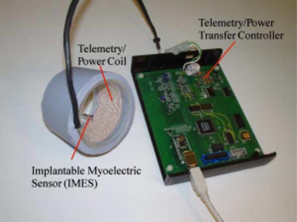
Photograph of IMES system. The external coil will be laminated directly into the prosthetic interface. Signals from the implants in the arm, linked through the external coil, control the prosthesis via reverse telemetry. Implant power is supplied through the external coil using forward telemetry.
Fig. 2.
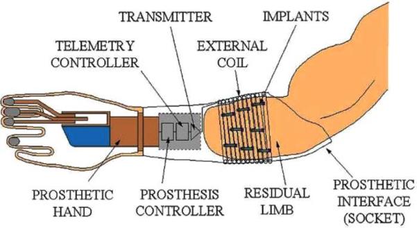
Schematic of how IMES, implanted in the muscles of the forearm, communicates via the external coil that is laminated in the prosthetic socket and encircles them when the prosthesis is worn.
The various control approaches fall broadly into one of three categories.
1) One Muscle—One Function or Direct Control
This is the most primitive approach, and represents current commercially available prosthetic devices. Direct control is the simplest form of control to implement, but users must learn to associate a particular control motion to a specific prosthesis function; thus, it is important to try and make the control motions physiologically relevant. Generally, the prosthetic component is driven at a speed that is proportional to the difference in the amplitude of the two EMG signals. If intuitive control motions can be found, direct control can provide simultaneous control of multiple DOFs for a prosthesis.
2) One Pattern of EMG Activity—One Function or Control Using Pattern Recognition
With pattern recognition, the controller recognizes a specific pattern of EMG signals and executes an associated function. These muscles produce relatively distinct patterns of activity with different movements of the phantom limb that can be linked to movements of the prosthesis. Pattern recognition approaches requires a pattern to be stored for every movement. These approaches do not provide true parallel/simultaneous control of multiple DOFs or dexterous manipulation of held objects [6]–[17].
3) Control by Forward Dynamic Simulation of the Intact Biomechanical System (Internal Model)
An internal model approach uses EMG signals measured in the user's residual muscles to predict muscle activation in an anatomically correct biomechanical muscle model of the intact limb [18], [19]. This method of control has been proposed for several powered exoskeleton designs [20]–[22]. Rosen et al. [23]–[27] have additionally completed a 7-DOF powered exoskeleton that is driven via an internal model. This method of control offers the potential to achieve true dextrous manipulation because of its ability to be able to execute movements that the controller has not been trained for while at the same time remaining transparent to the user. The muscle activations used to drive these models require focal EMG recordings from many small muscles.
B. Implications of Control Approaches for the IMES System
There are 18 extrinsic muscles in the forearm related to the control of the hand and wrist. Most of these are still present in some form following transradial amputation. The primary requirement of the IMES system was to be able to reliably obtain independent control signals from a relatively dense collection of small muscles. IMES have a sufficiently localized pickup field to be able to acquire EMG signals from the residual muscles of the forearm to provide estimates of the activation level for an internal model control approach; additionally, our IMES system is designed to be able to telemeter either raw EMG or integrated EMG out of the body depending on the control approach being used [28]. Pattern recognition requires raw EMG while an internal model approach can use integrated EMG.
Farrell and Weir [29] and Farrell [30] showed that pattern recognition with intramuscular EMG signals is as good as that with surface electrodes—whether the electrodes are targeted to specific muscle groups or not. Thus, the choice of whether to use intramuscular recordings versus surface recordings in a pattern recognition system is not driven by choice of classifier and classification accuracy but is instead driven by clinical issues relating to EMG signal robustness. The use of multiple surface EMG sensors for control has been shown to have signal reliability and robustness issues—due to electrode liftoff, skin impedance changes over the course of the day, movement artifacts, lack of repeatable electrode placement due to day-to-day donning and doffing of the prosthesis, as well as potential wire breakages. The IMES system offers a potentially robust, repeatable, and reliable alternative to capturing EMG signals because the implants are permanently encapsulated in fibrous scar tissue within the muscle [31]. This fibrous tissue does not impede signal transmission and prevents the implants from moving within the muscle. The implants operate in a constant environment—no skin impedance changes, no electrode liftoff issues. Since digital encoding is used to pass the EMG signals back to the external controller, small changes in the external reader coil position and orientation relative to the implant (due to donning and doffing or motion artifacts, for example) will not affect signal content.
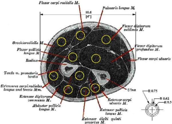
Simulations of the projected pickup area for our implants demonstrated the feasibility of recording independent EMG signals from the muscles of the forearm using chronically implanted IMES [32]. These results suggest that for an implant placed along the fibers of the muscle, the pickup area for the sensor will be an ellipsoid about 5 mm in radius about the implant (see Fig. 3).
Fig. 3.
Projected pickup area for our IMES superimposed on an appropriately scaled section through the proximal forearm. Image shows that pickup area should not be an issue in the final device with each device having a pickup area confined to an individual muscle.
By obviating the use of percutaneous wires in favor of fully implantable sensors, the IMES system has the potential to be a reliable and robust platform for any EMG measurement application where a coil, flat or circular, can be accommodated on the body. The Alfred E. Mann Foundation (AMF) bionic neuron (BION) has been approved for investigational use in human subjects and the BION package is robust and reliable [31]. The IMES systems are not limited to upper limb prosthesis control and have application in lower limb prosthetics as more powered components enter that field; in addition, IMES systems have applications in experimental research where intramuscular recordings need to be made over long periods of time [33].
C. IMES System Specifications
The IMES system is capable of measuring raw EMG at 8-bit resolution of up to 32 implants/sites at a sample rate of roughly 1000 samples/s/channel (see Table I for exact sample rates). Each implant is a bipolar differential instrumentation amplifier with an adjustable gain and adjustable high- and low-pass corner frequencies. Telemetered EMG can be sent back on one of two bands. Band 1 is low bandwidth that can be used to send back integrated EMG and band 2 is high bandwidth that can be used to send back raw EMG. The ability to measure raw EMG is important as a number of algorithms used to decipher user intent from the EMG signals extract features/information from the raw EMG that are lost if only integrated signals are passed out of the body.
TABLE I.
Approximate System Sampling Rates
| Number of Implants | 32 | 16 | 8 | 1 |
|---|---|---|---|---|
| Band 1 | 24S/s | 48S/s | 96S/s | 768S/S |
| Band 2 | 472S/s | 945S/s | 1.8kS/s | 15kS/s |
The high-pass and low-pass corners of the signal processing chain can be controlled by issuing commands over the magnetic link. This feature is useful in changing the antialiasing performance as sample rate is adjusted. In addition, the time constant of the integrating function used to generate the integrated EMG output is also adjustable. A summary of the programmable analog parameters is shown in Table II.
TABLE II.
Programmable Analog Parameters
| Setting | Range | Resolution |
|---|---|---|
| Amplifier Gain | 19dB–78dB | 64 Logarithmic steps |
| High-Pass Corner | 4Hz–70Hz | 16 Linear Steps |
| Low-Pass Corner | 200Hz–6.6kHz | 32 Linear Steps |
| EMG Integrator Time Constant | 2mS–35mS | 16 Linear Steps |
The internal 8-bit analog-to-digital converter (ADC) can be directed to sample the integrated EMG signal, the “raw” EMG signal, or the internal IMES power supply voltage. A data selector was added between the ADC output and the internal logic to allow readback of the IMES address byte, or any of the eight bytes of the 64-bit unique serial number (see Table III). Each IMES is identical except for its own 8-bit device address within the system and a unique 64-bit serial number.
TABLE III.
IMES Reverse Telemetry Modes Available
| Raw EMG | Used for prosthesis control |
|---|---|
| Integrated EMG | |
| Serial Number byte (0–7) | Device control and tracking purposes |
| 8-bit address | System diagnostics |
| Implant Power | Monitoring quality of magnetic link |
1) System Architecture
An IMES system consists of up to 32 IMESs, an external power coil and receiving antenna, and a telemetry controller. The telemetry controller passes data from the implants directly to the prosthesis controller or external recording device. The prosthesis controller is where high-level decisions are made as to operation of the telemetry controller, where the reverse telemetry data are processed to determine user intent, and where the motor control signals originate to drive the appropriate components in the prosthesis. The external power coil, receiving antenna, telemetry controller, and prosthesis controller are all housed in the prosthetic socket used to mechanically interface the user to the prosthetic components.
Implants are powered transcutaneously, via the external coil, with a 121-kHz magnetic field generated by an integrated high-efficiency class E power oscillator [34]. This powering magnetic field is modulated to send control signals to the addressable implants. EMG signals generated by the residual muscles at each implant site are amplified and digitized by the implants. The telemetry controller within the prosthesis controls a time-division multiplexing (TDM) sequence to orchestrate RF transmissions from each implant so that data from all implants may be sequentially collected by a receiver in the prosthesis. The telemetry controller demodulates the received signals and passes the multichannel EMG data to a prosthesis controller.
The implant device address is used to assign unique operating parameters to each implant where necessary, including whether or not a particular implant is sending reverse telemetry EMG data (“active”). TDM constraints limit the number of active implants in the system; implants may be activated and deactivated in several milliseconds, so it is possible to intelligently and dynamically distribute the available EMG telemetry bandwidth among up to 255 implants used with a single controller.
The communications protocol and command set for the system is defined around a system architecture designed to support up to 32 active implants on each of two RF bands of operation, 60 kHz (Band1), and 6.8 MHz (Band2). Although the architecture will support simultaneous multiband operation of 64 active implants (2 channels × 32 implants per channel), the two available bands are intended as alternate real-time options should an external interfering signal preclude reliable data transmission on the selected band. Band 1 provides a very robust low rate data link, while Band 2 is a much higher rate link. The system described here is capable of data transfer on only one band at a time, but may be dynamically band-switched.
a) IMES implant design
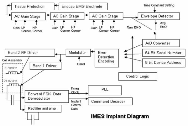
Each Implant is a single-chip integrated silicon device mounted on a ceramic substrate along with a surface-mount power supply filter capacitor. This sub-assembly is sandwiched between two halves of a cylindrical magnetic core. The 121-kHz power coil and the RF coil are then wound over the core. The electronics are encapsulated in a ceramic package that includes metal endcaps at either end between which serve as the differential recording electrodes (see Fig. 4).
Fig. 4.
IMES implant block diagram.
Tissue protection
Immediately following the endcaps is a tissue protection circuit. An elaborate protection network has been installed between the ac coupling capacitor and the input endcap electrode to prevent damaging currents from reaching the surrounding tissue. The fault protection circuit limits the voltage differential between electrodes to a maximum of 500 mV until a fusible poly1 resistor fails from electromigration due to the fault current. Based upon foundry process parameters, we predict that electromigration of the poly1 material will cause this resistor to fail open after approximately 30 min under fault conditions. On failure of the fusible resistor, current may no longer pass between electrodes. The current densities developed in the event of a failure do not exceed those cited as causing tissue damage as in Mortimer et al. [35]. Following the tissue protection circuitry, the signal enters the amplifier chain.
Amplifier chain
The amplifier is a precision, low-noise; programmable-gain ac-coupled front-end amplifier chain. As shown in Fig. 4, the EMG potential between the package end-caps is amplified by three stages of ac-coupled programmable-gain amplifiers. Any or all of which may be bypassed to provide 64 semilogarithmic gain settings: ranging from 24.1 dB, 125 mV full scale to 78.1 dB, 160 μV full scale. The gain is programmable via the command link logarithmically with a 6-bit resolution as shown in Fig. 4. The amplifier chain has an input-referred noise of 15 μVrms with a 1.0 Hz−1 kHz bandwidth, and includes 1-kHz antialiasing filters. An envelope detector with a variable time constant follows the amplifier chain to offer a lower bandwidth (Band 1) view of EMG activity (see Table II). Either the envelope-detected (Band 1) or wideband EMG (Band 2) may be dynamically selected. The selected signal is then passed to the A/D converter.
A/D converter
The A/D is a low-power 8-bit charge-redistribution ADC that can operate at up to 2MSPS. The implants may also be commanded to report on several values as reverse telemetry information to the telemetry controller, such as the implant's unique serial number or device address within the system.
Serial number and device address
In anticipation of the rigorous documentation required of devices intended for human implantation, each IMES contains a unique 64-bit LASER-programmed serial number. This serial number is permanently programmed at the die level, and is used to track the history of each IMES from die test to human implantation. There is also a programmable 8-bit address that is used for addressing commands to a specific implant while in operation. IMES in a single system must be assigned a unique address to ensure accurate reverse telemetry operation. The chip power supply Vdd, implant address, and serial number may be monitored for system diagnostic purposes (see Table III). For future expansion or experiments, the implant includes a selectable two-input multiplexer at the amplifier chain input, so one of two electrodes may be measured.
Implant control logic
The implant control logic consists of a command processor, a frame generator, and the PLL logic. An implant command set has been created for the inward telemetry stream to satisfy the implant control requirements of the system design. IMES implants have adjustable signal processing parameters that are set over the forward telemetry link (see Table I).
Error correction
There are several potential sources of bit error including PLL jitter, low signal-to-noise ratio conditions, or the presence of interference. To address this situation, a logic circuit internal to the implant calculates a 4-bit Hanning code from the 8 data bits. With error correction active, a total of 12 bits of telemetry bandwidth are used for each reporting time slot. We have found that by using error correction, usable control signals can be derived from data with up to a 15% bit-error rate [36].
Frequency-shift keying (FSK) demodulator
The FSK demodulator looks for frequency shifts in the 121-kHz exciter power, and demodulates these frequency shifts into a data stream. This data stream contains inward telemetry commands, and is fed to the implant control logic.
PLL
A PLL subsystem is used to generate the outward data carrier at 6.78 MHz, as well as to provide internal high-rate clock signals to the controlling logic in the implant. The outward data carrier and these high-rate clocks are phase-locked to the 121-KHz exciter frequency. Both the implant and the telemetry controller electronics contain identical PLLs, so the telemetry controller can accurately ascertain the timing in the implant for demodulation and time-slot bookkeeping. The implant design is such that a temporary loss of phase lock will only affect the precision of the reverse telemetry frequency, and will not affect the ability of the implant to interpret forward telemetry commands. PLL settling time is not an issue, since PLL settling occurs only on power-up of the implants.
Power
Implant power is provided by rectification and clamping of the magnetically induced 121-kHz exciter signal as acquired by a small receiver coil integral to the implant.
Implant assembly and testing
The IMES is automatically tested at four assembly levels:
-
1)
Die level—Unpackaged die are tested using a die probe station, with test signals applied through probes touching bond pads on the die surface.
-
2)
Subassembly—The die is attached to a ceramic substrate and sandwiched between two semicylindrical magnetic cores. Two coils are wound over the cores and die, and wire-bonded to the ceramic substrate. A surface-mount filter capacitor is also attached to the substrate. This sub-assembly is powered magnetically, and a test signal is applied to either end of the assembly.
-
3)
IMES—The subassembly is inserted into a ceramic cylinder along with some mechanical components and a chemical getter. An endcap is welded to seal the subassembly within the package. The IMES is powered magnetically, and the test signal is applied between the metal ends of the assembled device.
-
4)IMES in sterile packaging—The completed IMES is attached to a carrier printed circuit board using silicone rubber ties. This carrier board also holds two light-emitting diodes connected antiparallel across the endcaps of the IMES device. These LEDs serve two purposes;
-
a)to protect the IMES device from large electrostatic discharge events during storage;
-
b)to provide a source of a test-signal voltage through the transparent sterile packaging. The IMES and carrier board are sealed in a transparent sterilizable envelope. The LEDs within the bag are illuminated by a calibrated light source modulated with the test signal. The LEDs on the carrier board operate photovoltaically when illuminated and thus apply a test signal to the IMES endcaps. The IMES is powered magnetically during the test, so the IMES may be retested immediately prior to implantation without opening the sterile package.
-
a)
b) Telemetry controller
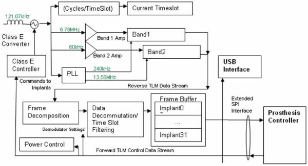
The telemetry controller (see Fig. 6) was constructed from discrete commercial devices and a custom “S5800b” Class E power oscillator controller device developed by Sigenics, Inc. [34]. This device includes the Class E oscillator control, FSK modulator, FET drivers, data first-in first-out, and serial interface. A programmable microcontroller is used to interpret high-level commands from the prosthesis controller and modulates the outgoing exciter frequency to provide forward telemetry to the implant via the external drive coil. A set of receiver circuits demodulates the reverse telemetry picked up by the receiving antenna and uses logic functions to decommutate the reverse telemetry data. The receiver components will eventually be integrated into custom silicon application-specified integrated circuit (ASIC) to reduce the size and power requirements of the prosthesis electronics. In the prototype, a universal serial bus (USB) interface is used by an external computer to communicate with the telemetry controller, allowing external computer control and display of implant parameters and collected EMG data. The USB interface may or may not be present in a final prosthetic system.
Fig. 6.
Block diagram of telemetry controller. Band 2 reverse telemetry frequency implemented: ISM band, 6.765–6.795 MHz (BW = 30 kHz) 25 μV/m at 300 m (Fc = 6.78 MHz). Identical allocations are present in USA (FCC Part 18) and Europe (EN50081). System supports 32 time slots, 8 cycles/timeslot best-case (10 data bits) = >15.6 ktimeslots/s = >1.9 ksps/implant with eight implants. Required reverse telemetry bandwidth: 502 kHz (BPSK modulation). Required bandwidth exceeds Part 18/EN50081 allocation, acceptable in view of low anticipated emissions. Part 15/EN50081 emission limits for unlicensed intentional radiators: 30 μV/m @ 30 m.
Microcontroller and firmware
The Texas Instruments In-corporated's MSP430 family of low-power microprocessors is used to perform the high-level telemetry controller functions, such as power and implant control as well as reverse telemetry decommutation. High-level programming is done in C, with lower-level data streaming routines programmed in assembler.
Receiver electronics and reverse telemetry
The integrated receiver subsystems connect to the receiving antenna through a passive R-C network(s), and delivers a serial stream of demodulated data to the telemetry controller. The receiver operates in one of the two command-selectable frequency bands; “band 1,” which is a 60-KHz nominal signal, BPSK-modulated, capable of 630-Hz total sampling bandwidth, and “band 2,” which is a 6.78-MHz nominal frequency, BPSK-modulated, and capable of 40.4 KHz of total sampling bandwidth. The receiver output is fed to a demodulator, which contains a copy of the PLL used in the implant. The receiver uses the exciter frequency as a reference, and generates a zero-phase reference carrier that matches exactly the frequency being emitted by the implant(s). The generated reference carrier is used to demodulate the reverse telemetry signal received from the implants, and supplies a data stream to the telemetry controller processor for decommutation.
Class-E converter and forward telemetry
A Class-E converter [34] is integrated into the design of the telemetry controller to provide power via an inductive magnetic link to the implants. FSK modulation of the 121-KHz nominal exciter frequency is used to pass commands to the IMES implants.
Interface
Communication with the prosthesis controller is over an extended serial port interface (SPI) interface. The interface operates in one of two modes; “command” in which configuration commands are passed from the prosthesis controller to the telemetry controller microprocessor, or “frame transfer mode” in which demodulated telemetry data is passed in discrete frames to the prosthesis controller. A USB interface that allows a stand-alone PC to operate in place of the prosthesis controller is also included.
c) Forward (inward) telemetry link
Commands are sent to the implants in the system by FSK modulating the 121-kHz powering magnetic field. The Class E 121-kHz power oscillator comprises essentially of a high-Q resonant circuit, which is excited by a very short high-current pulse once each cycle of 121 kHz. The implants use a patented method (U.S. patent no. 7271677) of FSK demodulation that compares the period of the current 121 kHz cycle to the average period of the 121-kHz magnetic field. To maintain a proper average, and thus, achieve optimal FSK data demodulation within the implant, a Manchester data encoding scheme is used to maintain an equal number of FHigh and FLow cycles during the transmission of an implant command. The data format used requires four 121 kHz cycles per transmitted bit, so the inward telemetry bit rate is 30 kbits per second.
d) Reverse (outward) telemetry link
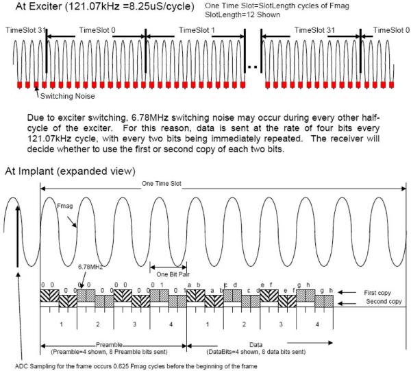
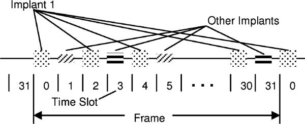
Implant data transmissions consist of bursts of a modulated RF carrier which occur in a 32 time slot TDM space (see Figs. 7 and 8). The 32 time slots, 0–31, are termed a “Frame.” Each implant contains a 32-bit time slot assignment table (TSA table) and its own time slot counter to keep track of the current time slot. The 32 active implants may each be assigned a different time slot, or multiple time slots in a frame may be assigned to the same implant to increase the EMG sampling rate for signals from that implant. This provides the ability to dynamically allocate signal bandwidth to implants. System sampling rates for various numbers of implants are shown in Table I.
Fig. 7.
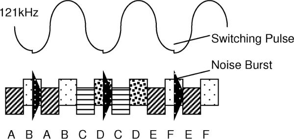
Diagram showing the current telemetry data format.
Fig. 8.
Time slot illustration.
The 121-kHz magnetic field generated by the Class E power oscillator is used as the frequency reference for all signals generated in the system. By synchronizing the implant RF carriers to the system-wide 121-kHz powering field, the RF carrier frequency of all the implants is identical and known, thereby simplifying the task of demodulation. RF carrier generation in the implant is accomplished by division (Band 1) or multiplication (Bands 2) of the 121-kHz reference frequency using a divider or PLL in each implant. The time slot counter in each implant is also clocked by the 121-kHz reference frequency, and a global “ReSync” implant command exists that causes all implants to zero their individual time slot counters almost simultaneously, thereby maintaining time slot alignment of all implants in the system.
In order to accommodate any implant-to-implant variation of 121-kHz reference phase shift due to subtle differences in physical orientation, each implant transmission contains a data preamble and carrier phase reference (see Figs. 7 and 9). Using the preamble, the demodulator establishes the reference carrier phase (“Phase 0”) as well as bit synchronization. During the early portion of the preamble, the telemetry controller demodulator also performs I and Q (see Fig. 10) demodulation at the RF frequency to determine the optimal phase with which to synchronously detect the RF carrier. In the interest of system optimization, the number of preamble and data bits, as well as the guard gap between time slots is dynamically programmable via the 121-kHz FSK command link to the implants.
Fig. 9.
Implant transmission format—band 1 (60 kHz).
Fig. 10.
Redundant data transmission—band 2 (6.8 MHz).
The data format in Band 2 is identical to that in Band 1, but each bit is sent twice in a time interleaved fashion (see Figs. 7 and 10). The current switching pulses in the Class E oscillator generate appreciable amounts of RF energy at the Band 2 frequency. This RF interference is large in amplitude but relatively short in duration. To allow data transmission in the presence of this interference, data bits in Band 2 are sent twice. The synchronous nature of the system design insures that one copy of the data will be received. The orientation of the implant in the magnetic field determines where the noise pulse lies in relation to the data, hence whether the first or second copy will be used.
II. Testing
Testing was conducted at a number of levels to both validate the design specifications and to demonstrate the ability of the IMES system to measure EMG signals in vivo. A progression of experiments—bench tests, in vitro tests, acute in vivo experiments, and chronic in vivo experiments provided this validation and demonstration of the IMES capabilities. The bench tests were performed to validate the various IMES system components and design specifications. An in vitro experiment demonstrated that the magnetic and RF link functioned correctly when an IMES was placed in muscle tissue, a necessary precursor to implanting IMES in cats. The animal experiments consisted of both a series of acute in vivo experiments to show the ability of the IMES system to accurately acquire physiologically generated EMG, and a series of chronic in vivo experiments to show the ability of the IMES to provide live EMG data reliably over time. In all experiments, the IMES implants are powered magnetically via the inductive link and telemetry is acquired via the reverse telemetry bands.
A. Protocols
1) Validation
An IMES system consisting of a telemetry controller, integrated magnetic drive with RF receiving antenna coil, and an IMES implant was validated on the bench against design specifications. The programmable amplifier gain and the high and low corner frequencies were examined independently for deviation from specifications. A random selection n = 10 from each set was evaluated and compared to the value specified in the design. A set of sine wave test signals, varying logarithmically from 1 Hz to 10 KHz, was used to characterize the system. IMES data was recorded via a custom LabVIEW 7.1 (National Instruments, TX) virtual instrument configured to interface with the Sigenics IMES telemetry server. The test signal set was created using a LabVIEW 7.1 virtual instrument and output via a National Instruments NI-6221 A/D board. Samples were generated at a minimum rate of 50 samples per period.
2) System Comparison
The IMES system was then compared to a Noraxon TeleMyo 2400 (Noraxon, AZ) wireless EMG system. The Noraxon TeleMyo is a 16-channel commercially available EMG acquisition system commonly used in clinical research. The system response of the Noraxon system was determined by passing our sine wave test signal set through one channel of the TeleMyo 2400. The gain, and high and low filter cutoff frequencies were determined as earlier. Using the system response characteristics of both systems, a set of setup parameters was chosen to most closely match the setup for the two systems. This was done because we were interested in determining how closely the IMES response would match that of the Noraxon System for a given set of setup parameters. Both systems then recorded an alternating series of positive and negative step functions n = 100 occurring at 1 Hz to provide an estimate of the step response of both systems. The low frequency of the step function allowed both EMG recording systems to return to steady state after being perturbed.
3) In Vitro
Once the bench tests were completed and as a precursor to testing the IMES system with live animals the IMES system was evaluated in an in vitro model. This in vitro model consisted of a shank of lamb complete with bone. A shank of lamb was chosen because it has muscle tissue surrounding a longitudinal long bone(s), and cross-sectional area similar to that of a human forearm. A 15-mm long incision was made 12-mm deep oriented parallel to the long bone of the lamb shank. An IMES implant was placed into the incision and sutured and closed. A stimulating monopole electrode was placed about 5 mm from each of the IMES endcaps, to the same depth as the IMES, oriented in a line with the implant. A pair of fine wire electrodes were implanted to the same depth as the IMES directly beside the implant, and connected to the Noraxon system for system comparison. A series of individual short-duration (100–1000 μS) monophasic stimulus pulses were input across the monopole electrode pair to induce a response in the EMG recording devices.
4) In Vivo (Acute)
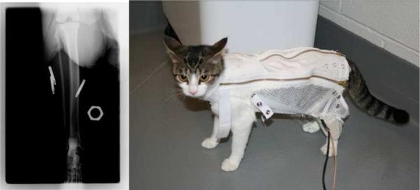
Having determined correct functioning of the IMES system on the bench, performance of the IMES in vivo was evaluated in both an acute and chronic animal preparation. For the acute preparation, the goal of the experiment was to use the cross-extension reflex [37] of a decerebrated cat preparation to elicit a natural EMG signal and to see how well the IMES system measured this signal. The crossed extension reflex is by definition a natural form of activation, producing normal recruitment and rate modulation [38]. The muscles can be simultaneously excited by eliciting the crossed-extension reflex in a decerebrated cat. Cats were chosen because the calf muscles of the cat are similar in size and orientation to the small muscles of the human forearm [38]. In this experiment, three IMES implants were implanted into the ankle extensor muscle group in the cat (calf muscles); lateral gastrocnemius (LG), medial gastrocnemius (MG), and soleus (S) (see Fig. 11).
Fig. 11.
(Right)X-ray of acute IMES implantation. Five-millimeter hexagonal marker used for scale. (Left) Animal wearing jacket and telemetry coil.
The deeply anesthetized (1–3% isoflurane) animal was mounted in a rigid stereotaxic frame (Kopf Instruments). The extensor muscle group was surgically exposed, leaving all major nervous and vascular structures intact. A cuff electrode was placed around the tibial nerve before the branching plexus of the nerve to form the medial gastrocnemius and lateral gastrocnemius-soleus nerves. The medial gastrocnemius and lateral gastrocnemius-soleus nerve branches were also dissected and marked using colored threads. Each IMES was implanted by means of a surgical cutdown into the belly of the target muscle with the long axis of the IMES oriented (see Figs. 11 and 12) parallel to the muscle fibers. The incision was closed via three simple interrupted sutures (4–0 silk). This orientation was chosen to minimize the predicted pickup volume of the IMES [32]. The implantation location was chosen to minimize physical separation for evaluation of the IMES pickup volume. A set of bipolar fine wire electrodes were implanted into each of the muscles, parallel to and to the same depth as the IMES implant for use with the Noraxon system. The skin was stapled shut over the surgical site to prevent dehydration of the tissues.
Fig. 12.
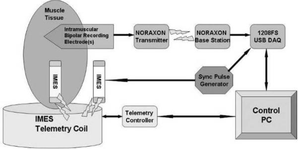
Acute in vivo experimental schematic diagram.
The power/telemetry coil was slid over the hind limb, and oriented with the implant location. The IMES system was initialized, and connection with the IMES devices was established to confirm function before implantation. The animal is decerebrated as per [39]. Gaseous anesthesia was then discontinued, and the animal was allowed to breathe room air. Typically, 30–60 min is needed before the crossed extension reflex can be elicited.
Direct stimulation EMG was elicited by stimulation of the nerve directly via the nerve cuff using a Grass stimulator (PSIU6) (200-μS pulse width, 10 Hz, 10 pulses). Stimulation consisted of several trains of monophasic pulses. Stimulus intensity ranged from threshold to four times threshold. Separate recordings were made for each level of stimulus intensity. EMG was also elicited via the crossed extension reflex. The crossed extension reflex was activated by administering painful stimuli to the contralateral hind paw of the animal or by direct electrical stimulation consisting of high-frequency monophasic pulses to the tibial nerve of the contralateral hind limb. The reflex causes the muscles of other limb to contract generating natural EMG signals as a consequence. Multiple crossed extension events were recorded for each animal.
Crosstalk and IMES field sensititivity were evaluated by severing the MG branch of the tibial nerve that was identified previously. Direct stimulation and crossed-extension elicited EMG were both acquired again, per earlier. Severing the MG branch of the tibial nerve eliminates the myoelectric activity of the MG. After all data had been recovered, the animal was euthanized.
5) In Vivo (Chronic)
Evaluation of chronic IMES system function was performed by inserting IMES implant(s) into the tibialis anterior (TA) and lateral gastrocnemius (LG) of three cats and allowing the implantation site to completely heal. The TA and LG are agonist-antagonistic foot muscles (i.e., ankle flexor vs. ankle extensor); as such they tend to be excited out of phase with each other during normal walking—allowing us to measure two independent signals, and at the same time, to see what sort of crosstalk the IMES would pick up between these two muscles.
Implantation was performed in a sterile surgical suite under a general anesthetic (isoflurane). A small incision in the lower hind limb over the muscles was made, and the implants were placed into the muscle tissue via small incisions and sutured closed as in the acute procedure, but with absorbable suture (4-0 Vicryl). Immediately postimplantation, a sterilized power/telemetry coil was placed around the implantation site and the IMESs were powered magnetically and ordered to transmit their numeric identifiers to confirm that the implants were not damaged during implantation. The skin incision was then closed, and the animal allowed to heal for a minimum of one week before experiments began. A custom cat jacket (Harvard Scientific) was modified with a set of elastic straps to contain a small, silicon-encased power/telemetry coil. The cats had been acclimated to the jacket and coil apparatus for a period of two weeks prior to implantation, and reacclimated for a minimum of two days postrecovery. Acclimatization was accomplished by putting the cat into the instrumented jacket and engaging in various enrichment and reward activities. EMG was acquired during natural walking. Natural walking is encouraged by enrichment toys and food rewards. Data was acquired at 6050 sps per implant. IMES internal filter corner frequencies are set at 4 Hz and 6600 Hz, respectively.
III. Results and Discussion
A. Validation and System Comparison
High and low corner frequency fidelity were determined by plotting signal amplitude against frequency and calculating frequencies at which the amplitude of the measured signal dropped to −3 dB of the maximum measured signal amplitude. System parameters of the TeleMyo 2400 system were calculated in the same manner. The set of programmable IMES parameters that most closely resemble the Noraxon system response are shown in Table IV. To determine the step response of both systems, a 50-s segment of each record was divided into 5-s windows for averaging purposes. For each time window, the Noraxon and IMES responses to the input step function were synchronized in time by use of cross correlation.
TABLE IV.
IMES and Noraxon Telemyo System Parameters
| System | Range | Range |
|---|---|---|
| MES | 2520 | 23Hz–1650Hz |
| TeleMyo 2400 | 3000 | 25Hz–1500Hz |
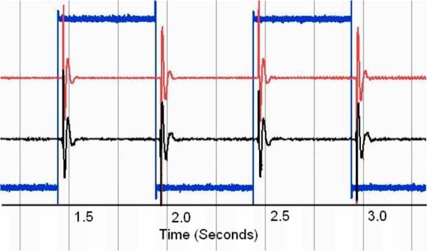
The time synchronization algorithm used is to calculate the normalized continuous rms voltage levels for both records and make use of the maximum cross-correlation point to allow for time synchronization. Note that in the presented data, there is a slight time delay from the stimulus signal being presented before the Noraxon system responds. This delay is constant across all recordings and is approximately 10 ms in duration, which is three times the delay the SPI interface for the IMES will provide. We synchronized the IMES system to the Noraxon system response to allow for clarity in presentation and data processing. To increase the accuracy of our comparison, both signals are postprocessed with a 25–1000 Hz third-order Butterworth bandpass filter to eliminate low-frequency motion artifacts in the Noraxon data channel. The signals are aligned in time and the cross correlation of the two signals is calculated as a measure of signal similarity. The postprocessing filter ensures that equal bandwidth signals are being compared which increases the accuracy of cross-correlation measurements. We have found that by configuring the programmable IMES parameters such that they produced a similar system response to the TeleMyo, and by postprocessing both data sets, we are able to show a high degree of cross correlation between the step responses of the two systems. The mean n = 10 of the maximum cross correlation values is 0.850. This degree of cross-correlation shows that the IMES system will produce a response similar to that of an EMG system that is currently in clinical use, suggesting that the IMES system is able to measure EMG accurately (see Fig. 13).
Fig. 13.
Characteristic normalized (voltage) step response of both systems. Timescale in seconds. Center trace, IMES 2520 sps. Top trace Noraxon 3000 sps. Bottom trace input signal 3000 sps.
B. In Vitro
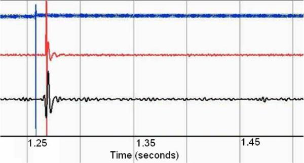
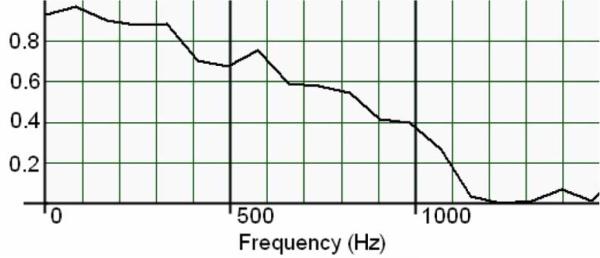
A series of five discrete impulse responses from both systems were postprocessed with a 25–1000 Hz third-order Butter-worth bandpass filter to remove motion artifacts. An additional 60-Hz third-order Butterworth band-stop filter was applied to the Noraxon data to remove power supply noise (see Fig. 14). The stimulus and recorded signals were normalized and compared by cross correlation and magnitude-squared coherence. Magnitude-squared coherence was calculated by rms averaging of 500 sequential windows of data from both data series the frequency bin size thus being dependent on total signal duration. The mean n = 5 of the maximum cross-correlation values is 0.767, which indicates that there may be a small degree of signal divergence. This may be associated with the physical geometry of the IMES device endcaps versus the fine wire recording electrodes, which have different spatial filtering properties [40]. This spatial filtering effect can be seen in the magnitude-squared coherence plot in Fig. 15. This shows a high degree of coherence at low frequencies, with the correlation in frequency falling off as the frequency increases, which would be expected with nonlinear spatial filters.
Fig. 14.
Characteristic normalized (voltage) impulse response of both systems through tissue. Timescale in seconds. Bottom trace, IMES 2520 sps. Center trace Noraxon 3000 sps. Top trace input signal 3000 sps.
Fig. 15.
Magnitude-squared coherence of IMES vs. noraxon TeleMyo to a 1000-μs pulse through tissue. Nominal frequency bin size 82.2 Hz.
C. In Vivo (Acute)
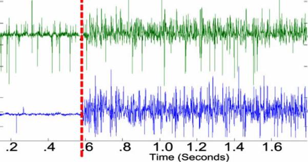
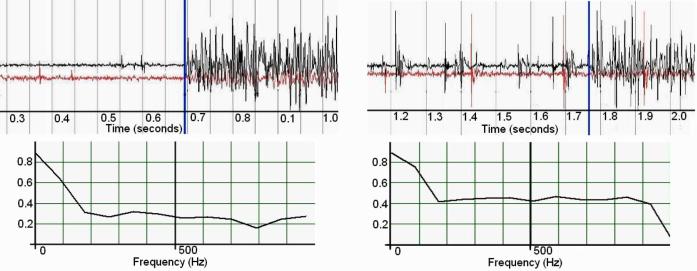
One second of each reflex event containing both pre- and postonset EMG data was processed (see Fig. 16.) Comparison of the recorded IMES signal to the recorded Noraxon signal in individual muscle(s) was accomplished by cross correlation and examining the magnitude-squared coherence between the two signals. Both signals were postprocessed with a 25–1000 Hz third-order Butterworth bandpass filter to remove motion artifacts. The filtered signals were then normalized. Maximum cross correlation between signals does not exceed 0.080, which is to be expected from devices that are measuring composite signals from multiple sources. Evaluation of the pickup field of the IMES is accomplished by comparing the rms voltage of the detected signal in the medial gastrocnemius before and after the medial gastrocnemius is denervated. Average rms voltage measured in the medial gastrocnemius during a crossed reflex extension decreases to less than 5% of the rms voltage measured in the Soleus (average of 27 mm separation between implants) during the same reflex event. This corresponds to the levels predicted by Lowery et al. [32]. One can also see the increase in MSC of the detected IMES signals indicating that crosstalk now accounts for a larger percentage of the total signal detected in the medial gastrocnemius (this is because the magnitude squared coherence is a normalized quantity). Decrease in the rms of the signal coupled with an increase in coherence (see Fig. 17) suggest the detected signal is composed of crosstalk from the adjacent muscles while at the same time being within the absolute limits predicted by Lowery et al.
Fig. 16.
Characteristic normalized (voltage) data showing the onset of the crossed extension reflex in the soleus of the acute cat. IMES shown in top. Noraxon shown in bottom. Reflex onset indicated by vertical marker bar.
Fig. 17.
(Left) Intact medial gastrocnemius nerve. (Right) Medial gastrocnemius de-enervated. Both graphs show onset of crossed extension reflex. Normalized (voltage) raw EMG (top) top trace is soleus, bottom trace is medial gastrocnemius. Vertical bar indicates reflex onset. Magnitude-squared coherence (bottom)—on the left is the MSC before denervation, on the right is MSC postdenervation. Nominal frequency bin size 87.9 Hz.
D. In Vivo (Chronic)
One second of data chosen at random during the course of normal walking was used for comparison (see Fig. 18). Both signals were normalized and postprocessed with a 25–1000 Hz third-order Butterworth bandpass filter to remove motion artifacts. The acquired EMG from the chronic in vivo experiments shows a maximum cross correlation of 0.09. Magnitude-squared coherence between the two measured signals does not exceed 0.40, and for most of the recording spectrum, coherence is lower than 0.10. These coherence and cross-correlation values show a distinct independence between signals attesting to the ability of the IMES system to make focal EMG measurements from multiple muscles in close proximity without picking up excessive crosstalk.
Fig. 18.
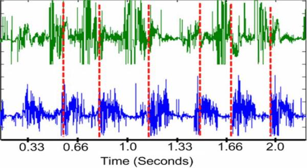
Normalized (voltage) characteristic gait cycle data as acquired with the IMES system originally recorded with a maximal peak–peak amplitude of 1.99 mV. 6050 sps. Tibialis anterior on top. Lateral gastrocnemius on bottom. Vertical dashed line is estimate of paw contact.
E. General Discussion
During the course of these experiments a number of issues had to be addressed. The nature of the USB interface necessitated the development of signal processing techniques that allow accurate comparison of signals acquired from disparate sources. This synchronization relies on the presence of distinct time stamps in both data streams. These time stamps were either impulse or step responses in the bench top experiments, or single motor unit action potentials in the acute cat experiments. It is important to remember that this synchronization is only necessary when trying to correlate signals acquired by the IMES with signals from a second data acquisition system; data acquired from multiple IMES remains synchronous. Another issue that had to be addressed was due to the nature of the PLL in the IMES implants. The resonant frequency of the class E oscillator can be influenced by the presence of ferrous materials in or near the magnetic field. This frequency shift propagates through all aspects of the IMES system operation. To address the effect the frequency shift has on sampling rate; all recorded signals were resampled to the nominal sampling frequency by means of spline interpolation. The frequency shift also affects the nominal reverse telemetry frequency, and can increase the amount of bit error the system sees due to shifting the reverse telemetry frequency outside of the range of frequencies the antenna and associated circuitry is designed to accommodate. This has been partially addressed by altering the filter corner frequencies on the receiving antenna circuitry to accommodate a larger range of frequencies. During the course of the initial acute experiments, an additional issue was discovered. The IMES implants in those experiments had an unacceptably high bit-error rate after implantation. A thorough examination of the ASIC design revealed a pair of positive temperature-biased transistors in the PLL circuitry which were slightly out of spec, leading to larger than predicted frequency shifts when the implants were operating at body temperature. To address this issue, the nominal operating frequency of the IMES system was decreased to compensate for the slight increase in the carrier of the reverse telemetry signal. This has been remedied in the current revision of the implant ASICs. It uses pair of matched positive and negative temperature-biased transistors to maintain a reliable telemetry frequency independent of temperature.
F. Ongoing Work
We are continuing to monitor the three chronic animals for signs of implant migration and to provide data for the analysis of data over time, with which we plan to address the consequences of device encapsulation on both data and signal quality. To date, we have not seen signs of implant migration or a decrease in the quality of telemetry signal and have not seen a qualitative decrease in the EMG data but are awaiting the conclusion of the study period to perform a quantitative analysis of the chronic EMG data. We are additionally in the process of performing an in-depth quantitative analysis of all of our data in order to address the reliability and consistency as regards the data acquisition abilities of the IMES system.
IV. Conclusion
An IMES system has been developed. The IMES system is capable of measuring focal intramuscular EMG comparable in both the time and frequency domain to commercially available clinical EMG systems. The use of implantable sensors in place of percutaneous wires makes the IMES system a reliable and robust platform for any EMG measurement application where a coil, flat, or circular, can be accommodated on the body. Although originally designed with the control of upper-limb prostheses in mind, the IMES system is not limited to upper-limb prosthesis control and has application in lower-limb prosthetics as more powered components enter that field. In addition, IMES systems have application in experimental research where intramuscular recordings need to be made over long periods of time [33]. Using IMES obviates the need for percutaneous wires. As such, the IMES system can be viewed as a platform technology for making long-term intramuscular recordings. We have demonstrated the functionality and reliability of the system on the bench and we have fully operational systems that have been tested both acutely and chronically in cats. Implants have been chronically implanted in the legs of three cats and are still completely operational 9 months after implantation. Clinical experience with implantation indicates minimal surgical difficulty in implantation and minimal discomfort. Future research will include evaluation of the IMES system for multifunction prosthesis control.
Fig. 5.
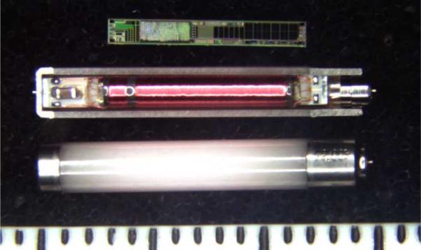
Photograph of IMES components in three assembly states. (Top) IMES silicon chip. (Middle) Sectioned IMES capsule containing IMES subassembly. (Bottom) Completed IMES implant. Shown next to 1 mm scale.
Acknowledgment
R. F. ff. Weir and J. F. Schorsch would like to thank Dr. C. J. Heckman, M. Johnson, and J. Miller for their expertise and assistance as well as Dr. D. Berger and Dr. C. Cain, and the staff of the Northwestern Center for Comparative Medicine for their advice and assistance with the care of their chronic animals. They would also like to thank J. Madoff for her expertise in developing signal processing algorithms.
Biographies

Richard F. ff. Weir (S'92–M'92) is Director of the Biomechatronics Development Laboratory at the Rehabilitation Institute of Chicago. Dr. Weir is also a Research Healthcare Scientist for the Jesse Brown VA Medical Center, Chicago, IL. In addition, Dr. Weir holds Research Associate Professor appointments in the Departments of Physical Medicine & Rehabilitation and Biomedical Engineering at Northwestern University, Evanston, IL. Dr. Weir's research interests are in the area of the mechanical design and control of artificial hand/arm replacements. Dr. Weir's research covers all aspects of the problem ranging from neural control, mechatronic design and development, novel actuator technologies, and clinical deployment of these systems.
Phil R. Troyk (M'83–SM'91) has been President of Sigenics since its creation in 2000, Dr. Troyk is the former Director of the Center for Integrative Neuroscience and Neuroengineering (CINNR) and is currently an Associate Professor at the Illinois Institute of Technology. He holds thirteen patents related to polymer coatings, power conversion, medical implant design, power conversion and radio-frequency telemetry systems. Dr. Troyk is a prolific author, and has written several papers on subjects related to neurosciences and implantable medical devices. Dr. Troyk is the technical driving force behind Sigenics's development of several implantable devices designed to be used in neural prostheses.
Glen A. DeMichele (M'01) is a Director of Sigenics. In addition to being a founding principal of Sigenics, Mr. DeMichele was president of Upstream Engineering Services, a software and hardware company providing services to the U.S. Government's Naval Research Laboratory. Upstream developed the ground-based test system for the NRL's WindSat satellite program, as well as systems to analyze and catalog of X and S band RADAR pulses.
Mr. DeMichele has been involved with the Illinois Institute of Technology and the National Institutes of Health (NIH) developing system-level approaches and mixed mode integrated circuits for use in the Visual Prosthesis Program. Other circuits and system designed by Mr. DeMichele include bi-directional magnetic biotelemetry of data from embedded strain gauges, EMG sensors and microstimulators, and passive RFID systems.
Mr. DeMichele was an Analog Field Applications engineer at Harris Semiconductor Corporation (now Intersil) where he applied his expertise to problems in a wide variety of commercial and military applications. Mr. DeMichele also has designed biological laboratory and petroleum processing instrumentation with Precision Scientific Corp., military power systems with Northrop Corporation, and commercial avionics communications equipment with Rockwell/Collins in Cedar Rapids IA. Mr. DeMichele is the holder of seven patents and has published numerous articles for trade and scientific journals.

Douglas A. Kerns is a Director of Sigenics. Before founding Sigenics, Dr. Kerns was president of ESI, a firm specializing in the design of integrated electronic sensors, such as those used to measure acceleration, gas concentrations, mechanical strain, radiation, and temperature. Dr. Kerns also worked for Tanner Research developing software tools used in integrated circuit design, as an analog designer at Analog Devices Inc., and at the Jet Propulsion Laboratory in Pasadena California. Dr. Kerns expertise in integrated circuit fabrication technology has allowed Sigenics to successfully fabricated devices in over 12 different IC processes. Dr. Kerns has also authored numerous papers and holds two patents.
Dr. Kerns received an undergraduate degree in electrical engineering from Northwestern University, and masters and doctoral degrees in electrical engineering from Caltech. Dr. Kerns has worked as an IC design engineer for Tanner Research Inc., for Analog Devices Inc., and as an independent contractor. In 2000, he co-founded Sigenics Inc. as a microelectronic engineering services company. Dr. Kerns heads the Sigenics office in Sierra Madre CA.
Jack F. Schorsch received his undergraduate degree in biomedical engineering from Tulane University in 2002. He then worked as the design engineer for the department of physiology at the Loyola University Medical center in Chicago. In 2006 he received a masters degree in medical device and diagnostic engineering from the University of Southern California while also working for the Alfred E. Mann Institute. He is currently the research manager for the Biomechatronics Development Laboratory at the Rehabilitation Institute of Chicago. His research interests include micro-miniature implantable devices, sensor/stimulation of muscle tissue, and neural control algorithms.

Huub Maas obtained a M.Sc. and cum laude Ph.D. degree from the Faculty of Human Movement Sciences at the VU University Amsterdam (The Netherlands) in 2003. He then worked as a postdoctoral fellow at the School of Applied Physiology of the Georgia Institute of Technology in Atlanta (USA) and as a research associate at the Department of Physiology of Northwestern University in Chicago (USA). His research interests include muscular force transmission, muscle mechanics and proprioceptive feedback in neural control of locomotion, as well as processes of muscle and connective tissue adaptation. In 2008, he returned to the Faculty of Human Movement Sciences in Amsterdam to study the biomechanical and neuromuscular response to tendon transfers for which he received the Marie Curie International Reintegration Grant of the European Union.
Footnotes
Color versions of one or more of the figures in this paper are available online at http://ieeexplore.ieee.org.
References
- [1].Dhillon GS, Horch KW. Direct neural sensory feedback and control of a prosthetic arm. IEEE Trans. Neural Syst. Rehabil. Eng. 2005 Dec.13(no. 4):468–472. doi: 10.1109/TNSRE.2005.856072. [DOI] [PubMed] [Google Scholar]
- [2].Atkins DJ, Heard DCY, Donovan WH. Epidemiologic overview of individuals with upper-limb loss and their reported research priorities. J. Prosthet. Orthot. 1996;8(no. 1):2–11. [Google Scholar]
- [3].Childress DS, Weir RF. Control of limb prostheses. In: Smith DG, Michael JW, Bowker JH, editors. Atlas of Amputations and Limb Deficiencies—Surgical, Prosthetic and Rehabilitation Principles. American Academy of Orthopaedic Surgeons; Rosemont, IL: 2004. [Google Scholar]
- [4].Weir RF. Design of artificial arms and hands for prosthetic applications. In: Kutz M, editor. Standard Handbook of Biomedical Engineering and Design. McGraw-Hill; New York: 2003. pp. 32.1–32.61. [Google Scholar]
- [5].Weir RF, Childress DS. Research trends for the 21st century. In: Meier Robert H., III, Aitkins ODJ., editors. Functional Restoration of Adults and Children with Upper Extremity Amputation. Demos Medical; New York: 2004. [Google Scholar]
- [6].Lawrence P, Kadefors R. Proc. Control Upper Extremity Prostheses Orthoses. Göteborg, Sweden: 1971. Classification of myoelectric patterns for the control of a prosthesis; pp. 190–200. [Google Scholar]
- [7].Taylor D, Finley F. Proc. Control Upper Extremity Prostheses Orthoses. Göteborg, Sweden: 1971. Multiple-axis prosthesis control by muscle synergies; pp. 181–189. [Google Scholar]
- [8].Taylor D, Wirta R. Development of a myoelectrically controlled prosthetic arm. Advances in External Control on Human Extremities; Third Int. Symp. External Control Human Extremities; Dubrovnik, Yugoslavia. 1969. [Google Scholar]
- [9].Wirta R, Taylor D, Finley F. Pattern recognition prostheses: A historical perspective—Final report. Bull. Prosthet. Res. 1978;10:8–35. [PubMed] [Google Scholar]
- [10].Herberts P, Almstrom C, Kadefors R, Lawrence P. Hand control via myoelectric patterns. Acta Orthop. Scand. 1973;44:389–409. doi: 10.3109/17453677308989075. [DOI] [PubMed] [Google Scholar]
- [11].Graupe D, Salahi J, Zhang DS. Stochastic-analysis of myoelectric temporal signatures for multifunctional single-site activation of prostheses and orthoses. J. Biomed. Eng. 1985;7(no. 1):18–29. doi: 10.1016/0141-5425(85)90004-4. [DOI] [PubMed] [Google Scholar]
- [12].Hudgins B, Parker P, Scott RN. A new strategy for multifunction myoelectric control. IEEE Trans. Biomed. Eng. 1993 Jan.40(no. 1):82–94. doi: 10.1109/10.204774. [DOI] [PubMed] [Google Scholar]
- [13].Farry K, Fernandez J, Abramczyk R, Novy M, Atkins D. Applying genetic programming to the control of an artificial arm. Proc. Myoelectr. Control Conf.: Issues Upper Limb Prosthet.; Fredericton, NB, Canada. 1997. pp. 50–55. [Google Scholar]
- [14].Ajiboye AB, Weir RF. A heuristic fuzzy logic approach to EMG pattern recognition for multifunctional prosthesis control. IEEE Trans. Neural Syst. Rehabil. Eng. 2005 Sep.13(no. 3):280–291. doi: 10.1109/TNSRE.2005.847357. [DOI] [PubMed] [Google Scholar]
- [15].Chan FHY, Yong-Sheng Y, Lam FK, Yaun-Ting Z, Parker PA. Fuzzy EMG classification for prosthesis control. IEEE Trans. Rehabil. Eng. 2000 Sep.8(no. 3):305–311. doi: 10.1109/86.867872. [DOI] [PubMed] [Google Scholar]
- [16].Almström C, Herberts P, Körner L. Experience with Swedish multifunctional prosthetic hands controlled by pattern recognition of multiple myoelectric signals. Int. Orthop. 1981;5:15–21. doi: 10.1007/BF00286094. [DOI] [PubMed] [Google Scholar]
- [17].Englehart K, Hudgins B, Parker PA. A wavelet-based continuous classification scheme for multifunction myoelectric control. IEEE Trans. Biomed. Eng. 2001 Mar.48(no. 3):302–311. doi: 10.1109/10.914793. [DOI] [PubMed] [Google Scholar]
- [18].Birdwell JA, Weir RF. Forward-dynamic musculoskeletal models of the human arm and hand. Great Lakes Biomed. Conf.; Racine, WI. 2008. [Google Scholar]
- [19].Birdwell JA, Weir RF. Hill-based musculo-skeletal hand models for controlling multi-DoF hand prostheses. Soc. Neurosci. Annu. Meeting; San Diego, CA. 2007. [Google Scholar]
- [20].Gonzalez RV, Abraham LD, Barr RE, Buchanan TS. Muscle activity in rapid multi-degree-of-freedom elbow movements: Solutions from a musculoskeletal model. Biol. Cybern. 1999 May;80(no. 5):357–367. doi: 10.1007/s004220050531. [DOI] [PubMed] [Google Scholar]
- [21].Gonzalez RV, Buchanan TS, Delp SL. How muscle architecture and moment arms affect wrist flexion-extension moments. J. Biomech. 1997 Jul.30(no. 7):705–712. doi: 10.1016/s0021-9290(97)00015-8. [DOI] [PubMed] [Google Scholar]
- [22].Gonzalez RV, Hutchins EL, Barr RE, Abraham LD. Development and evaluation of a musculoskeletal model of the elbow joint complex. J. Biomech. Eng., Trans. ASME. 1996 Feb.118(no. 1):32–40. doi: 10.1115/1.2795943. [DOI] [PubMed] [Google Scholar]
- [23].Cavallaro EE, Rosen J, Perry JC, Burns S. Real-time myoprocessors for a neural controlled powered exoskeleton arm. IEEE Trans. Biomed. Eng. 2006 Nov.53(no. 11):2387–2396. doi: 10.1109/TBME.2006.880883. [DOI] [PubMed] [Google Scholar]
- [24].Perry JC, Rosen J, Bums S. Upper-limb powered exoskeleton design. IEEE-ASME Trans. Mechatronics. 2007 Aug.12(no. 4):408–417. [Google Scholar]
- [25].Rosen J, Brand M, Fuchs MB, Arcan M. A myosignal-based powered exoskeleton system. IEEE Trans. Syst., Man, Cybern. A, Syst. Humans. 2001 May;31(no. 3):210–222. [Google Scholar]
- [26].Rosen J, Fuchs MB, Arcan M. Performances of Hill-type and neural network muscle models—Toward a myosignal-based exoskeleton. Comput. Biomed. Res. 1999 Oct.32(no. 5):415–439. doi: 10.1006/cbmr.1999.1524. [DOI] [PubMed] [Google Scholar]
- [27].Rosen J, Perry JC. Upper limb powered exoskeleton. Int. J. Humanoid Robot. 2007 Sep.4(no. 3):529–548. [Google Scholar]
- [28].Mason M, Salisbury J. Robot Hands and the Mechanics of Manipulation. MIT Press; Cambridge, MA: 1985. [Google Scholar]
- [29].Farrell TR, Weir RF. A comparison of electrode implantation and targeting on pattern classification accuracy for prosthesis control. IEEE Trans. Biomed. Eng. doi: 10.1109/TBME.2008.923917. to be published. [DOI] [PMC free article] [PubMed] [Google Scholar]
- [30].Farrell TR. Dissertation. Dept. Biomed. Eng., Northwestern Univ.; Evanston, IL: 2007. Multifunctional prosthesis control: The effects of targeting surface vs. intramuscular electrodes on classification accuracy and the effect of controller delay on prosthesis performance. [Google Scholar]
- [31].Arcos I, David R, Fey K, Mishler D, Sanderson D, Tanacs C, Vogel M, Zilberman Y, Schulman J. Second-generation microstimulator. Artif. Organs. 2002 Oct.26(no. 3):228–231. doi: 10.1046/j.1525-1594.2002.06938.x. [DOI] [PubMed] [Google Scholar]
- [32].Lowery MM, Weir RF, Kuiken TA. Simulation of intramuscular EMG signals detected using implantable myoelectric sensors (IMES) IEEE Trans. Biomed. Eng. 2006;53(no. 10):1926–1933. doi: 10.1109/TBME.2006.881774. [DOI] [PubMed] [Google Scholar]
- [33].Prilutsky B, Maas H, Nichols T, Gregor R. Effects of self-reinnervation of selected cat ankle extensors on their activity and hindlimb mechanics in slope walking. Soc. Neuroscience Annu. Meeting; Atlanta, GA. 2006. [Google Scholar]
- [34].Schwan M, Troyk PR. Suspended carrier modulation for transcutaneous telemetry links. 13th Int. Symp. Biotelem.; Williamsburg, VA. 1995. pp. 27–32. [Google Scholar]
- [35].Mortimer J, Kaufman D, Roessmann U. Intramuscular electrical stimulation: Tissue damage. Ann. Biomed. Eng. 1980;8(no. 3):235–244. doi: 10.1007/BF02364479. [DOI] [PubMed] [Google Scholar]
- [36].Weir RF, Troyk PR, DeMichele GA, Kerns DA. Technical details of the implantable myoelectric sensor (IMES) system for multi-function prosthesis control. 27th Annu. Int. Conf. IEEE Eng. Med. Biol. Soc. (EMBS)—Innovation Biomol. Biosyst.; Shanghai, China. 2005. [DOI] [PubMed] [Google Scholar]
- [37].Kandel E, Schwartz J, Jessell T. Principles of Neural Science. McGraw-Hill; New York: 2000. p. 715. [Google Scholar]
- [38].Sacks R, Roy R. Architecture of the hind limb muscles of cats: Functional significance. J. Morphol. 1982;173:185–195. doi: 10.1002/jmor.1051730206. [DOI] [PubMed] [Google Scholar]
- [39].Heckman CJ, Miller J, Munson M, Paul K, Rymer WZ. Reduction in postsynaptic inhibition during maintained electrical stimulation of different nerves in the cat hindlimb. J. Neurophysiol. 1994;71:2281–2293. doi: 10.1152/jn.1994.71.6.2281. [DOI] [PubMed] [Google Scholar]
- [40].Farina D, Merletti R, Enoka R. The extraction of neural strategies from the surface EMG. J. Appl. Physiol. 2004;96:1486–1495. doi: 10.1152/japplphysiol.01070.2003. [DOI] [PubMed] [Google Scholar]


