Abstract
Background
Microwave ablation is an emerging tumor ablation modality. To date, microwave systems have generally utilized single large-diameter antennas to deliver high input powers.
Objective
To determine whether spatially distributing power through an array of multiple smaller antennas creates a more uniform thermal profile and increases peripheral tissue temperatures when compared with microwave ablation using a single larger antenna.
Methods
Microwave ablations were performed in ex vivo bovine liver using a single 2.45-GHz magnetron generator and a constant total input power (90 W) delivered through either a single 13-gauge antenna, two 17-gauge antennas, or three 18-gauge antennas. Multiple antennas were driven coherently. Temperatures were recorded at 5-mm radial distances and the resulting thermal profiles and ablation zones were compared using analysis of variance.
Results
Multiple-antenna configurations were less invasive (ie, the area of tissue punctured was smaller) than the single-antenna configuration; despite this, ablation zones created using multiple smaller antennas were larger and as circular when compared with those created using a single larger antenna. Multiple-antenna configurations resulted in more uniform thermal profiles and higher peripheral tissue temperatures.
Conclusion
Distributing power evenly among multiple smaller antennas resulted in larger ablation zones with more uniform thermal profiles than more invasive ablations with a larger single antenna.
INTRODUCTION
Microwave ablation is an emerging tumor ablation modality that offers several theoretical advantages when compared with the current clinical standard, radiofrequency (RF) ablation. Microwaves can heat tissue faster than RF current, and heating occurs in a larger volume around the applicator. In addition, tissue charring does not hinder the propagation of microwaves in the same way that it limits current flow during RF ablation. Therefore, while tissue temperatures must be kept below 100 °C during RF ablation, they can be driven considerably higher during microwave ablation.1,2 Theoretically, higher central tissue temperatures can result in larger ablation zones due to the increased thermal gradient near the applicator, increasing thermal conduction to the periphery. However, Schramm and Haemmerich demonstrated that the majority of tissue heating during MW ablation is due to direct (ie, dielectric) heating and that the effects of thermal conduction are largely mitigated by tissue perfusion.2 Higher-power antennas generate electric fields that penetrate deeper into the tissues resulting in larger volumes of direct heating and, subsequently, larger volumes of ablation. Unfortunately, the power that an antenna can safely handle is directly proportional to its diameter. Therefore, large input powers have required relatively large antennas, which are associated with more tissue trauma and are generally more invasive when compared with RF.3–5
Aside from establishing a thermal gradient, tissue temperatures greater than 60 °C contribute little to treatment efficacy because cellular death occurs almost instantaneously above 60 °C.6 Therefore, much of the energy used to create very high temperatures is “wasted” if it is applied to tissue that is already necrotic. For this reason, a single large antenna appears to be an inefficient means of delivering energy to a large volume of tissue. Ideally, the target tissue would be actively and uniformly heated to cytotoxic temperatures without excessively heating already necrotic tissue.
Spatially distributing power through an array of applicators may create a more uniform thermal profile and increase the likelihood that cytotoxic temperatures are reached near the periphery of the target tissue. The feasibility of this approach has already been demonstrated in two separate studies.1,7 Those studies identified thermally synergistic interactions between individual microwave antennas in an array, which resulted in larger zones of coagulation than would be expected from sequential activation of the same number of antennas. However, total energy delivered by three antennas was three times larger than assumed for the single antenna; neither study compared the zone of coagulation to that created by a larger single antenna with the same total input power. The increase in total power and subsequent increase in ablation volume was also achieved at the expense of increased invasiveness (ie, total cross-sectional area of tissue punctured). Each antenna within an array was the same size and delivered the same power as antennas used for single-antenna ablations. In other words, both the total input power and area of tissue punctured for the multiple-antenna ablations were three times that of a single antenna.
In addition to increasing maximum input power, arrays of microwave antennas can also be used to more evenly distribute a given input power throughout the target volume. Furthermore, the invasiveness of the technique can be maintained or decreased if the size of the antennas is decreased as the number of antennas is increased. For example, Hines-Peralta et al.3 previously reported the ability to create approximately 6-cm ablation zones in an in vivo porcine liver model using a single large-diameter antenna (5.7 mm). Subsequently, Brace et al.7 reported equally large ablation zones created by delivering similar total input power through an array of three smaller antennas (1.5 mm). To date, no direct comparison has been made between systems utilizing multiple small-diameter antennas and those employing a single large antenna with similar input power and relative invasiveness. Therefore, the purpose of this study was to determine whether utilizing multiple smaller antennas could increase the efficiency and uniformity of power delivery during microwave ablation when compared with microwave ablation using a single larger antenna.
MATERIALS & METHODS
A. Experimental Setup
Three experimental groups were used for this study. Group 1 (n = 10) consisted of single-antenna microwave ablations performed using a 13-gauge triaxial antenna with an assumed maximum power handling of 90 W. Groups 2 and 3 (n = 10 each) consisted of microwave ablations performed using two 17-gauge or three 18-gauge coherently driven triaxial antennas, respectively. The assumed maximum power handling for 17-gauge or 18-gauge antennas were 45 W and 30 W, respectively, which were based on manufacturer datasheets (Micro-Coax, Pottstown, PA). The number and size of antennas used in each group were chosen with the intention of maintaining a similar total cross-sectional puncture area (Table 1).
Table 1.
Power Distribution and Invasiveness
| Configuration | Total Input Power (W) | Input Power per Antenna (W) | Diameter of Single Antenna (mm) | Puncture Area per Antenna (mm2) | Total Puncture Area (mm2) |
|---|---|---|---|---|---|
| 13 gauge | 90 | 90 | 2.3 | 4.15 | 4.15 |
| 2 × 17 gauge | 90 | 45 | 1.5 | 1.77 | 3.54 |
| 3 × 18 gauge | 90 | 30 | 1.2 | 1.13 | 3.39 |
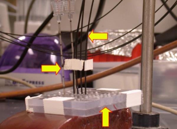
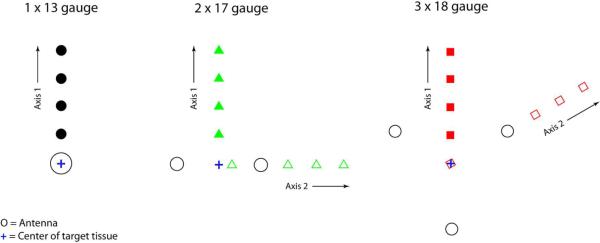
Figure 1 and Figure 2 depict the experimental setup. Microwave ablations were performed for 5 minutes using triaxial antennas placed in freshly excised bovine liver. The total applied power was 90 W for all ablations and was split evenly amongst the antenna array; therefore, each 13-, 17- and 18-gauge antenna received 90, 45 and 30 W, respectively. The two 17-gauge and three 18-gauge antennas were placed in 1.5-cm linear and 2.0-cm triangular configurations, respectively, for optimal power distribution in each configuration. Based on preliminary experiments, these antenna spacings maximized the size of the ablation zones while maintaing a relatively regular (ie, circular) shape in cross-section. An acrylic template was used to maintain proper antenna placement. Fiberoptic temperature sensors (Luxtron, Santa Clara, CA) were used to measure temperatures at 0.5-cm intervals away from the center of the target tissue. The probes were inserted to a depth equal to the proximal end of the radiating element, which is approximately the level of maximum tissue heating. During five of the multiple-antenna ablations, temperatures were recorded at points along an axis that bisected two antennas (Figure 2, Axis 1). It was expected that the temperatures would be most limiting on this axis, and these measurements were used to compare maximum temperatures among groups. During the other five multiple-antenna ablations, temperatures were recorded along an axis running through the center of the target tissue and an antenna (Figure 2, Axis 2). These temperatures were used to account for the asymmetry of the multiple-antenna ablations and were used in the interpolation (see below) to generate surface plots and isotherms.
Figure 1.
Experimental setup. In this example, two 17-gauge triaxial antennas (right arrow) separated by 1.5 cm were inserted through an acrylic template (up arrow) into freshly excised bovine liver. Four fiberoptic thermosensors (Luxtron, left arrow) were placed 0.5, 1.0, 1.5, and 2.0 cm from the center of the array to a depth equal to that of the base of the antenna (the depth at which the electric field peaks).
Figure 2.
Antenna and temperature sensor configurations. 17- and 18-gauge antennas were separated by 1.5 and 2.0 cm, respectively. During half of the multiple-antenna ablations, temperatures were recorded 0.5, 1.0, 1.5 and 2.0 cm from the center of the target tissue along an axis that bisected two antennas (Axis 1). During the other multiple-antenna ablations, temperatures were recorded along an axis running through the center of the target tissue and an antenna (Axis 2).
B. Microwave System
The triaxial microwave ablation system has been described previously.7–10 Briefly, the generator consists of a single, 2.45-GHz magnetron capable of delivering up to 300 W of continuous-wave power (Cober-Muegge LLC, Norwalk, CT). Power splitters (SM Electronics, Fairview, TX) were used to divide power equally between multiple antennas. Radio-grade (RG400/U) coaxial cables of equal length were used to transfer power from the splitter to the antennas. Generator output and reflected powers were measured continuously. The triaxial antennas were created from low-loss, semi-rigid coaxial cable (Micro-Coax Inc., Pottstown, PA) and introducer needles (Bard Medical, Covington, GA).
C. Ablation Zone Measurements
Ablation zones were sliced into approximately 5-mm thick transverse sections, and a representative slice was chosen from the middle of the ablation zone for measurement. Standard ablation zone measurements such as diameter, isoperimetric ratio (IR), and cross-sectional area were measured and analyzed using the freeware ImageJ (National Institutes of Health, Bethesda, MD). Ablation zone diameters were defined by transverse lines running through the center of the array or the insertion path of a single antenna. Isoperimetric ratio estimates the roundness of an ablation, where values near 1.0 indicate nearly circular zones of ablation.11,12
D. Statistical Analysis
The statistical means and standard deviations of ablation zone measurements were calculated. Analysis of variance (ANOVA) was used to detect differences in ablation zone size, shape, and maximum temperatures among groups. Post-hoc t-tests were used to check for significant differences between specific groups.
The `griddata' function and `v4' method of MATLAB (version 7.0; The Mathworks, Natick, MA) were used to fit surfaces to the temperature measurements. The function is based on the method of interpolation described by Sandwell13 and was used to determine 50 °C isotherms from measured temperatures.
Two calculations were performed to assess the efficiency and uniformity of energy delivery. The ablation-to-invasiveness ratio was calculated by dividing the cross-sectional area of the ablation zone by the total cross-sectional (ie, puncture) area of the antennas used to create it, which may impact the risk of certain complications.14 This calculation was performed to normalize the volume of coagulation to the invasiveness of the technique. The range of maximum temperatures measured within individual ablation zones was calculated to provide a measure of the uniformity of coagulation.
RESULTS
A. Ablation Zone Size and Shape
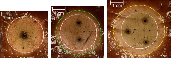
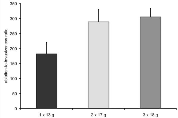
Table 2 lists the ablation zone size measurements and Figure 3 depicts representative ablation zones for each of the groups. Ablations created using three 18-gauge antennas were significantly larger than those created using one 13-gauge antenna (P < .05, minimum diameter; P < .01, maximum diameter; P < .001, cross-sectional area). Mean maximum diameter and cross-sectional area were significantly larger when using two 17-gauge antennas (3.9 cm and 10.2 cm2, respectively) when compared with using one 13-gauge antenna (3.2 cm and 7.5 cm2, respectively; P < .001, both comparisons). The only significant difference between the 17- and 18-gauge groups was for mean minimum diameter (two 17-gauge antennas, 2.9 cm; three 18-gauge antennas, 3.3 cm; P < .05). Figure 4 shows ablation-to-invasiveness ratio for cross-sectional area. The ratio was substantially higher for ablation zones created using two 17-gauge (289) or three 18-gauge (305) antennas when compared with those created using a single 13-gauge antenna (182). In other words, using two 17-gauge and three 18-gauge antennas increased the efficiency of energy delivery by 59% (107/182) and 68% (123/182), respectively, when compared with a single 13-gauge antenna.
Table 2.
Ablation Zone Size and Shape
| Configuration | Minimum Diameter (cm) | Maximum Diameter (cm) | Area (cm2) | Isoperimetric Ratio |
|---|---|---|---|---|
| 13 gauge | 2.9 ± 0.4a | 3.2 ± 0.4b,c | 7.5 ± 1.6b,d | 0.94 ± 0.07 |
| 2 × 17 gauge | 2.9 ± 0.3a | 3.9 ± 0.4 | 10.2 ± 1.5 | 0.93 ± 0.04 |
| 3 × 18 gauge | 3.3 ± 0.2 | 3.7 ± 0.2 | 10.3 ± 1.0 | 0.93 ± 0.03 |
| ANOVA P value | 0.0098 | 0.0004 | 0.0001 | 0.8742 |
There were ten samples in each group and values are given as mean ± standard deviation.
P < .05 versus 3 × 18 gauge.
P < .001 versus 2 × 17 gauge.
P < .01 versus 3 × 18 gauge.
P < .001 versus 3 × 18 gauge.
Figure 3.
Cross-sections of microwave ablation zones created using a single 13-gauge antenna (A, yellow circle), two 17-gauge antennas (B, blue circle), and three 18-gauge antennas (C, green circle). Note the increased size and similar shape of multiple-antenna ablation zones despite the same total input power.
Figure 4.
Ablation-to-invasiveness ratio. The ratio was calculated by dividing mean ablation zone cross-sectional area by the total cross-sectional area of the antennas used for the ablation—4.15, 3.54, and 3.39 mm2 for one 13-, two 17-, and three 18-gauge antennas, respectively.
B. Ablation Zone Temperatures
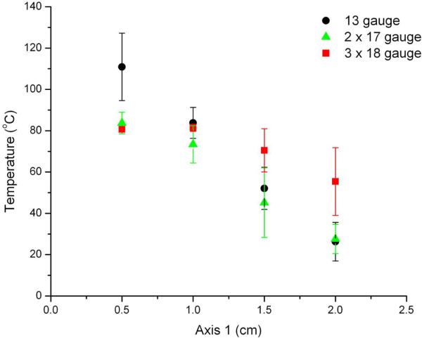
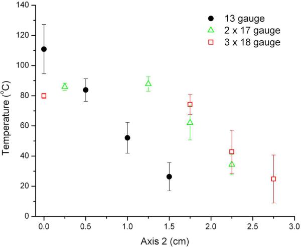
Figure 5 depicts the maximum temperatures measured within ablation zones for each of the groups. The highest temperatures observed at the 0.5- and 1-cm measurement points occurred during ablations performed with a single 13-gauge antenna (mean temperature at 0.5 cm, 110.9 °C; P < .05 vs 17- and 18-gauge groups). However, temperatures 2 cm from the center of the target area were significantly higher during ablations performed with three 18-gauge antennas (mean, 55.4 °C) when compared with those performed using a single 13-gauge antenna (26.3 °C, P < .01) or two 17-gauge antennas (27.6 °C, P < .01). The range of temperatures measured was significantly smaller for the 18-gauge group (mean, 26.3 °C) when compared with the 13-gauge (84.5 °C) and 17-gauge (56.1 °C) groups. In other words, ablations performed using three 18-gauge antennas resulted in more uniform thermal profiles when compared with either of the other groups.
Figure 5.
Maximum tissue temperatures recorded along Axis 1 (A) and Axis 2 (B) shown in Figure 2. Temperatures near the center of the target tissue were highest during ablations performed using a single 13-gauge antenna. Ablations performed with three 18-gauge antennas resulted in the highest temperatures near the periphery (>1.5 cm from the center of the tissue) as well as the most uniform temperature distribution.
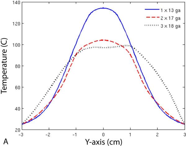
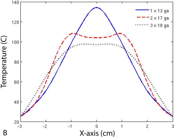
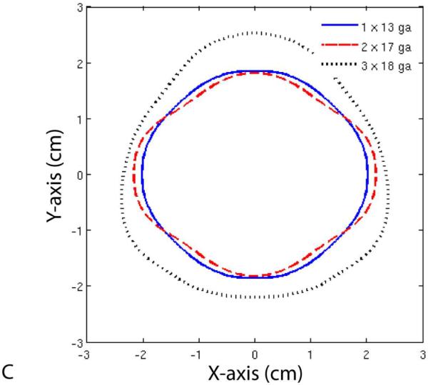
Finally, Figure 6 shows temperature profiles for each of the three groups. Note that the maximum diameter of the 50 °C isotherm was larger for the 17-gauge group when compared with the 13-gauge group, but not the minimum diameter. On the other hand, the 50 °C isotherm diameter was greater in all directions for the 18-gauge group when compared with the other two groups.
Figure 6.
Temperature profiles (A, B) and 50 °C isotherms (C) for single- and multiple-antenna groups. Note that the 50 °C isotherms during two-antenna ablations were greater than during single-antenna ablations along the axis of the antennas (B), but not perpendicular to it (A). In contrast, ablations with three 18-gauge antennas resulted in greater 50 °C isotherms in all directions when compared with those performed with one 13-gauge or two 17-gauge antennas.
DISCUSSION
The results of our study demonstrate that multiple smaller antennas can be used to distribute microwave power more uniformly over an area of tissue. Instead of delivering all the power at the center of the ablation zone, the power is distributed throughout the target volume. This leads to lower (but still cytotoxic) temperatures at the center of the ablation zone, higher temperatures toward the periphery of the ablation zone, and an increase in the size of the ablation zones. Heating tissue uniformly is a more efficient use of energy, given that cells heated to 60 °C are already necrotic, and that tissue temperatures fall off rapidly further away from antennas. Despite the linear and triangular configurations of the arrays, multiple-antenna zones of ablation were as circular in cross-section as single-antenna ablations. Importantly, the increase in the size of the ablation zone was accomplished without a corresponding increase in invasiveness (ie, total puncture area of the applicators). In fact, the total puncture area of the 17- and 18-gauge configurations (3.54 and 3.39 mm2, respectively) was less than that of the 13-gauge applicator (4.15 mm2). In other words, the efficiency of power delivery was increased with multiple antenna arrays, reflected by a higher ablation-to-invasiveness ratios observed in the 17- and 18-gauge groups.
Brace et al.7 and Wright et al.1 have previously discussed some of the advantages of multiple-antenna microwave ablation when compared with single-antenna ablation. In particular, multiple-antenna systems can rapidly ablate disproportionately larger volumes of tissue in less time and with less complexity than overlapping single ablations due to the concept of thermal synergy. The disadvantage of using the techniques described in those studies is that each antenna was the same size, and operated at the same power level as a single antenna. Therefore, the invasiveness of the multiple-antenna groups was three times that of each single-antenna ablation. While using multiple antennas was more efficient than overlapping sequential single ablations, techniques are needed that increase the size of the ablation zone while maintaining (or decreasing) the invasiveness of the procedure. For example, when compared with the results of Hines-Peralta et al.,3 Brace et al.7 achieved similar volumes of ablation by delivering similar input power through three smaller antennas (versus a single larger one) while reducing the cross-sectional area of the tissue punctured (5.3 mm2 versus 25.5 mm2, respectively).
Uniformly distributing power is not the only technique by which the size of the ablation zone can be increased without a corresponding increase in invasiveness. Switching between multiple antennas delivers more power to the target area and creates larger ablation zones when compared with a single larger antenna.15 Constructively phasing arrays of antennas can also be used to dramatically increase heating in certain areas of tissue (by N2, where N is the number of antennas).16–18 It is likely that further increases in the efficiency of energy delivery would be achieved by combining one or more of these techniques.
This study was limited by the use of an ex vivo model. Perfusion has well documented detrimental effects on thermal ablation.12,19 However, given that the periphery of the ablation zone is the most vulnerable to perfusion-mediated cooling, it is likely that the benefit achieved by uniformly distributing power will translate to an in vivo environment. Percutaneous placement of several antennas in the optimal spatial configuration may be difficult to achieve in certain cases due to limited access. However, it is not anticipated that this will be a problem given the extensive experience using other multiple-applicator systems in widespread clinical use today (eg, cryoablation, RF ablation and laser ablation).20–22
CONCLUSION
Distributing power evenly among multiple smaller antennas resulted in larger zones of ablation with more uniform temperatures across the ablation zone than more invasive ablations with a larger single antenna. More efficient and less invasive techniques may help increase the effectiveness of ablation procedures while reducing the risk of procedural complications.
ACKNOWLEDGMENT
The authors wish to thank Lisa Sampson and Tina Frey for their assistance with data collection.
This work was supported in part by the National Institutes of Health under Grant 1R01CA108869-01A2.
REFERENCES
- 1.Wright AS, Lee FT, Jr, Mahvi DM. Hepatic microwave ablation with multiple antennae results in synergistically larger zones of coagulation necrosis. Ann Surg Oncol. 2003;10:275–283. doi: 10.1245/aso.2003.03.045. [DOI] [PubMed] [Google Scholar]
- 2.Schramm W, Yang D, Haemmerich D. Contribution of Direct Heating, Thermal Conduction and Perfusion during Radiofrequency and Microwave Ablation. Conf Proc IEEE Eng Med Biol Soc. 2006;1:5013–5016. doi: 10.1109/IEMBS.2006.259288. [DOI] [PubMed] [Google Scholar]
- 3.Hines-Peralta AU, Pirani N, Clegg P, et al. Microwave ablation: results with a 2.45-GHz applicator in ex vivo bovine and in vivo porcine liver. Radiology. 2006;239:94–102. doi: 10.1148/radiol.2383050262. [DOI] [PubMed] [Google Scholar]
- 4.Simon CJ, Dupuy DE, Iannitti DA, et al. Intraoperative triple antenna hepatic microwave ablation. AJR Am J Roentgenol. 2006;187:W333–40. doi: 10.2214/AJR.05.0804. [DOI] [PubMed] [Google Scholar]
- 5.Yu NC, Lu DS, Raman SS, et al. Hepatocellular carcinoma: microwave ablation with multiple straight and loop antenna clusters--pilot comparison with pathologic findings. Radiology. 2006;239:269–275. doi: 10.1148/radiol.2383041592. [DOI] [PubMed] [Google Scholar]
- 6.Goldberg SN, Gazelle GS, Mueller PR. Thermal ablation therapy for focal malignancy: a unified approach to underlying principles, techniques, and diagnostic imaging guidance. AJR Am J Roentgenol. 2000;174:323–331. doi: 10.2214/ajr.174.2.1740323. [DOI] [PubMed] [Google Scholar]
- 7.Brace CL, Laeseke PF, Sampson LA, et al. Microwave ablation with multiple simultaneously powered small-gauge triaxial antennas: results from an in vivo swine liver model. Radiology. 2007;244:151–156. doi: 10.1148/radiol.2441052054. [DOI] [PubMed] [Google Scholar]
- 8.Brace CL, Laeseke PF, Sampson LA, et al. Microwave ablation with a single small-gauge triaxial antenna: in vivo porcine liver model. Radiology. 2007;242:435–440. doi: 10.1148/radiol.2422051411. [DOI] [PMC free article] [PubMed] [Google Scholar]
- 9.Brace CL, Laeseke PF, van der Weide DW, Lee FT. Microwave Ablation With a Triaxial Antenna: Results in ex vivo Bovine Liver. IEEE Trans Microw Theory Tech. 2005;53:215–220. doi: 10.1109/TMTT.2004.839308. [DOI] [PMC free article] [PubMed] [Google Scholar]
- 10.Brace CL, van der Weide DW, Lee FT, et al. Analysis and experimental validation of a triaxial antenna for microwave tumor ablation. IEEE MTTS Int Microw Symp. 2004;3:1437–1440. doi: 10.1109/MWSYM.2004.1338842. [DOI] [PMC free article] [PubMed] [Google Scholar]
- 11.Carmo MPd . Differential geometry of curves and surfaces. Prentice-Hall; Englewood Cliffs (NJ): 1976. [Google Scholar]
- 12.Chinn SB, Lee FT, Jr, Kennedy GD, et al. Effect of vascular occlusion on radiofrequency ablation of the liver: results in a porcine model. AJR Am J Roentgenol. 2001;176:789–795. doi: 10.2214/ajr.176.3.1760789. [DOI] [PubMed] [Google Scholar]
- 13.Sandwell DT. Biharmonic spline interpolation of GOES-3 and SEASAT altimeter data. Geophys Res Lett. 1987;14:139–42. [Google Scholar]
- 14.Geraghty PR, Kee ST, McFarlane G, et al. CT-guided transthoracic needle aspiration biopsy of pulmonary nodules: needle size and pneumothorax rate. Radiology. 2003;229:475–481. doi: 10.1148/radiol.2291020499. [DOI] [PubMed] [Google Scholar]
- 15.Brace CL, Laeseke PF, Sampson LA, et al. Switched-mode microwave ablation: A simple and robust method of power delivery. World Congress on Interventional Oncology; Washington, DC. 2007. [Google Scholar]
- 16.Trembly BS, Douple EB, Ryan TP, Hoopes PJ. Effect of phase modulation on the temperature distribution of a microwave hyperthermia antenna array in vivo. Int J Hyperthermia. 1994;10:691–705. doi: 10.3109/02656739409022448. [DOI] [PubMed] [Google Scholar]
- 17.Clibbon KL, McCowen A, Hand JW. SAR distributions in interstitial microwave antenna arrays with a single dipole displacement. IEEE Trans Biomed Eng. 1993;40:925–932. doi: 10.1109/10.245614. [DOI] [PubMed] [Google Scholar]
- 18.Furse CM, Iskander MF. Three-dimensional electromagnetic power deposition in tumors using interstitial antenna arrays. IEEE Trans Biomed Eng. 1989;36:977–986. doi: 10.1109/10.40798. [DOI] [PubMed] [Google Scholar]
- 19.Goldberg SN, Hahn PF, Tanabe KK, et al. Percutaneous radiofrequency tissue ablation: does perfusion-mediated tissue cooling limit coagulation necrosis? J Vasc Interv Radiol. 1998;9:101–111. doi: 10.1016/s1051-0443(98)70491-9. [DOI] [PubMed] [Google Scholar]
- 20.Laeseke PF, Frey TM, Brace CL, et al. Multiple-electrode radiofrequency ablation of hepatic malignancies: initial clinical experience. AJR Am J Roentgenol. 2007;188:1485–1494. doi: 10.2214/AJR.06.1004. [DOI] [PubMed] [Google Scholar]
- 21.Mack MG, Straub R, Eichler K, Sollner O, Lehnert T, Vogl TJ. Breast cancer metastases in liver: laser-induced interstitial thermotherapy--local tumor control rate and survival data. Radiology. 2004;233:400–409. doi: 10.1148/radiol.2332030454. [DOI] [PubMed] [Google Scholar]
- 22.Wang H, Littrup PJ, Duan Y, et al. Thoracic masses treated with percutaneous cryotherapy: initial experience with more than 200 procedures. Radiology. 2005;235:289–298. doi: 10.1148/radiol.2351030747. [DOI] [PubMed] [Google Scholar]


