Abstract
The use of fluorescence-based sensors holds great promise for continuous glucose monitoring (CGM) in vivo, allowing wireless transdermal transmission and long-lasting functionality in vivo. The ability to monitor glucose concentrations in vivo over the long term enables the sensors to be implanted and replaced less often, thereby bringing CGM closer to practical implementation. However, the full potential of long-term in vivo glucose monitoring has yet to be realized because current fluorescence-based sensors cannot remain at an implantation site and respond to blood glucose concentrations over an extended period. Here, we present a long-term in vivo glucose monitoring method using glucose-responsive fluorescent hydrogel fibers. We fabricated glucose-responsive fluorescent hydrogels in a fibrous structure because this structure enables the sensors to remain at the implantation site for a long period. Moreover, these fibers allow easy control of the amount of fluorescent sensors implanted, simply by cutting the fibers to the desired length, and facilitate sensor removal from the implantation site after use. We found that the polyethylene glycol (PEG)-bonded polyacrylamide (PAM) hydrogel fibers reduced inflammation compared with PAM hydrogel fibers, transdermally glowed, and continuously responded to blood glucose concentration changes for up to 140 days, showing their potential application for long-term in vivo continuous glucose monitoring.
Keywords: glucose-responsive fluorescence, long-lasting implantable sensor, biocompatible interface, implantable glucose sensor, diabetes mellitus
In vivo glucose monitoring allows continuous glucose monitoring (CGM) and facilitates intensive control of blood glucose concentrations in diabetic patients. Long-lasting implantable sensors can reduce the frequency of implantation and replacement, resulting in long-term in vivo glucose monitoring with less effort by patients and less tissue damage. For decades, implantable sensors for long-term use have been developed using enzyme electrodes. However, these methods have several drawbacks for long-term use because these enzyme based sensors are insufficiently stable in vivo (1), they are poorly accurate in low glucose concentrations (2), and their activity is oxygen-dependent (3). In contrast, glucose-responsive fluorescence is a promising approach that maintains long-lasting functionality in vivo due to its enzyme-free and reversible reaction (4–9). We recently developed fluorescent hydrogel microbeads that are transdermally detectable, injectable, minimally invasive, and biocompatible (10). To bring this technology closer to long-term application, the fluorescent hydrogel sensors need to remain at the implantation site for a long period (over 3 mo) and be easily removable after use; despite their great potential for continuous glucose monitoring, the microbeads were not suitable for long-term monitoring in vivo because they dispersed from the implantation site and were difficult to remove. In addition, the biointerface of the fluorescent hydrogel with tissues requires excellent biocompatibility to reduce the occurrence of inflammation, which decreases the life span and functionality of an implantable glucose sensor.
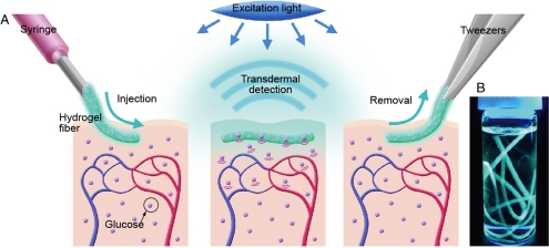
Here, we present a long-term in vivo glucose monitoring method using glucose-responsive fluorescent hydrogel fibers. To satisfy the aforementioned requirements, we improved two properties of the sensors with respect to the microbeads: the structures and the materials. First, we used a fiber structure for the sensor. The fibers are as injectable and minimally invasive as the microbeads because the fiber-type sensors can be implanted in alignment with the axial direction of an injection needle (Fig. 1A). Moreover, the fibers have three significant advantages over microbeads for long-term in vivo glucose monitoring: (i) The fibers can remain at the implantation site for an extended period (Fig. 1A), whereas the microbeads disperse from the implantation site; (ii) the fibers can be implanted with a readily controllable quantity of fluorescence by cutting them to a specified length, thereby enabling stable and repeatable sensor functionality; and (iii) the fibers are easily, nonsurgically removed from the body (Fig. 1A). Although the material is biocompatible, it is better to remove the fibers after use to minimize potential side effects.
Fig. 1.
(A) A schematic illustration of the fluorescent hydrogel fiber designed for long-term in vivo glucose monitoring. The fiber can be injected into subcutaneous tissues. The implanted fiber remains at the implantation site for a long period and transmits fluorescent signals transdermally depending on blood glucose concentration. The implanted fiber can be easily removed from the implantation site after use. (B) Fluorescent hydrogel fibers in a glass vial with a 50% glucose solution. The fibers are excited by ultraviolet light. The fluorescent image indicates that the glucose-responsive monomer is immobilized within the hydrogel fibers.
Second, the fiber material, a polyethylene glycol (PEG)-bonded polyacrylamide (PAM) enhanced the biocompatibility of the fiber-tissue interface. PEG, a well-known biomaterial (11), was covalently bonded to the fluorescent hydrogel fibers, thereby reducing inflammation (12, 13). These PEG-bonded fluorescent hydrogel fibers maintained glucose responsiveness and transmitted fluorescent signals transdermally for an extended period.
Results
Fabrication of the Fluorescent Hydrogel Fibers.
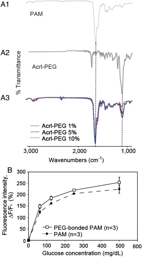
We immobilized the glucose-responsive monomer (see Fig. S1) (10) in hydrogel fibers that had been obtained by polymerizing a pregel solution in polyolefin microcapillaries coated with Pluronic® surfactant. To covalently bond PEG to acrylamide, Acryl-PEG was added to the pregel solution at concentrations of 1%, 5%, and 10%. After gelation, the hydrogel fibers were washed with large amounts of water for over 48 h to remove ungelled PEG and acrylamide monomer. Fluorescent image showed that the glucose-responsive monomer was immobilized within the hydrogel fibers with a diameter of 956 ± 9 μm (Fig. 1B). The fibers were polymerized in polyolefin microcapillaries of 1,000 μm in diameter. The diameters of the fibers were smaller than the diameter of a general syringe needle, thereby allowing easy injection into the body. We performed Fourier transform infrared (FTIR) spectroscopic analysis of the PAM hydrogel fibers with Acryl-PEG (MW = 480) at concentrations of 1%, 5%, and 10% to verify the copolymerization of PAM and PEG. There was a typical amide I band (at approximately 1,650 cm-1) in the spectrum of PAM (Fig. 2A1). The characteristic band of PEG was observed at approximately 1,100 cm-1 as a result of C-O asymmetric stretching (Fig. 2A2). The PAM hydrogels with PEG showed peaks not only at approximately 1,650 cm-1 but also at approximately 1,100 cm-1 (Fig. 2A3). These findings suggest that PEG successfully bonded to the PAM hydrogels. The amplitude of the peaks at approximately 1,100 cm-1 increased as the Acryl-PEG concentration was increased. However, the amplitude of this peak for the 10% PEG sample was slightly higher than that for the 5% PEG sample. We concluded that at concentrations over 5%, most of Acryl-PEG monomers in the pregel solution remained as ungelled form. Therefore, we chose the sample obtained from the pregel solution with 5% Acryl-PEG for subsequent verification.
Fig. 2.
(A) FTIR spectra of PAM, Acrl-PEG, and PEG-bonded PAM hydrogels: (A1) PAM; (A2) Acrl-PEG; (A3) PEG-bonded PAM spectra. The PAM hydrogels with PEG showed peaks at approximately 1,650 cm-1 and at approximately 1,100 cm-1 that are a typical amide I band and the characteristic band of PEG, respectively. (B) Glucose responsiveness of the fluorescent hydrogel fibers. The fluorescence intensity of the fibers changes according to the glucose concentration. Polymerization with PEG causes a difference in the sensitivity of the glucose-responsiveness.
In Vitro Glucose Responsiveness Test.
We tested the glucose responsiveness of the fluorescent hydrogel fibers in vitro. The fluorescent images were obtained at an emission wavelength of 488 nm with varying glucose concentrations (0–500 mg·dL-1) to verify the fibers’ glucose responsiveness within the normal (80–140 mg·dL-1), hypoglycemic (< 80 mg·dL-1), and hyperglycemic (> 140 mg·dL-1) ranges (14). When the glucose concentration increased from 0 mg·dL-1 to 500 mg·dL-1, the fluorescence intensity of the PAM and PEG-bonded PAM hydrogel fibers also increased depending on the glucose concentrations (Fig. 2B).
In Vivo Glucose Monitoring.
In vivo glucose monitoring was conducted using fibers implanted in the ear skin of mice; the ear skin is an excellent implantation site for a fluorescence-based glucose sensor due to its transparency (10). Our previously developed microbeads were dislodged and dispersed from the implantation site after 1 mo (see Fig. S2). In contrast, the implanted fibers remained at the implantation site for an extended period (see Fig. S3) because the increased contact area with subcutaneous tissue decreases the mobility of the subcutaneous implants.
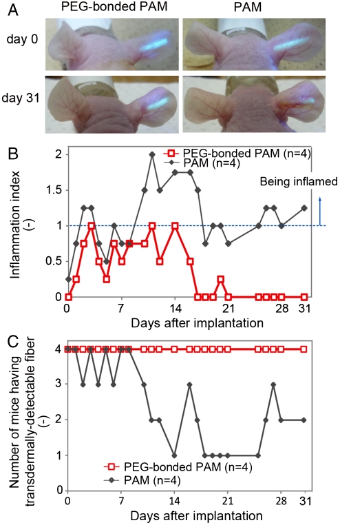
To test the effect of PEG on the biointerface of the fibers with tissues, we implanted PEG-bonded PAM hydrogel fibers into four mice and PAM hydrogel fibers into another four mice (see Fig. S4). We evaluated inflammation based on the color change (reddening), swelling, and scab formation of the ears (see Table S1 and Fig. S5). Immediately after implantation, both types of fibers were visible through ear skin over 100 μm thick (Fig. 3A and Movie S1). However, every PAM hydrogel fiber induced inflammation, which consequently reduced the transdermal fluorescence intensity (Fig. 3B and Fig. S6B). In contrast, three of four PEG-bonded PAM hydrogel fibers induced only mild inflammation, and recovery after inflammation was rapid. One PEG-bonded PAM hydrogel fiber did not induce any inflammation for a month (Fig. 3B and Fig. S6A). Furthermore, all PEG fibers glowed through the mouse ear skin (Fig. 3C). Therefore, we concluded that the inclusion of PEG reduced inflammation because PEG resists the adsorption of proteins such as albumin, fibrinogen, fibronectin, and others; these proteins modulate host inflammatory cell interactions and adhesion (15–17).
Fig. 3.
Inflammation induced by the implanted fibers and transdermal transmission over a long period. (A) The fluorescent PAM hydrogel fibers with and without PEG were implanted in mouse ears and remained in the mouse ears for one month. The fluorescence intensity of the fiber with PEG was observable through the ear skin for the entire month, whereas the fluorescence intensity of the fiber without PEG was barely detectable after one month. (B) Inflammation indices of the mouse ears with the fibers one month after implantation. Inflammation was evaluated based on reddening, swelling and scab formation for a month. The inflammation index was obtained by summing the reddening, swelling, and scab formation scores. If the ear skin showed any reddening, reddening scores 1 point; similarly, swelling and scab formation were each also scored 1. PEG-bonded PAM induced less inflammation than PAM only. (C) Numbers of mice showing transdermal transmission of fiber fluorescence. The fluorescence intensity of the PEG-bonded PAM hydrogel fibers could be detected through the ear skin for one month, whereas that of PAM fibers could not.
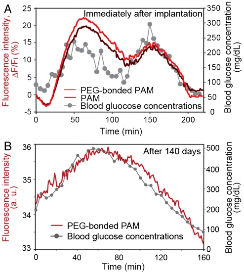
We demonstrated the fluorescence intensity of the implanted fibers in response to blood glucose concentrations in mice by glucose challenge. We injected glucose to temporarily elevate glucose concentrations to 300 mg·dL-1 (within the hyperglycemic range) and insulin to decrease glucose concentrations under 140 mg·dL-1 (within the euglycemic and hypoglycemic ranges). Blood glucose concentrations were measured with a blood glucose monitoring sensor (Accu-Chek, Roche) using a blood sample from the snipped tail. The fluorescence intensity was estimated from fluorescent images of mouse ears. Fig. 4 displays the measured blood glucose concentrations and the fluorescence intensity of the fibers over time. After implantation, the fluorescence intensity of both the PAM and the PEG-bonded PAM hydrogel fibers constantly tracked the fluctuations in blood glucose concentration for two up-and-down cycles (Fig. 4A). The glucose sensitivities of the implanted fibers were slightly different. This result is in agreement with the glucose responsiveness in vitro (Fig. 2B). The response of fluorescence intensity of the hydrogel fibers lagged 10 ± 5 min behind the change in blood glucose concentrations. The time lag results mainly from the delayed changes in subcutaneous interstitial glucose concentrations compared with the changes in blood glucose concentrations because fluorescence intensity reflects the glucose concentration in subcutaneous interstitial tissues.
Fig. 4.
In vivo continuous glucose monitoring in mice using the implanted fibers. (A) Continuous glucose monitoring using implanted fibers with and without PEG after implantation. The fluorescence intensity of the fibers constantly responded to blood glucose concentration over two up-and-down cycles. (B) Continuous glucose monitoring using the implanted PEG-bonded PAM hydrogel fiber 140 days after implantation. The fluorescence intensity of the fiber continuously corresponded to blood glucose concentration even after 140 days.
After about four months from implantation, we performed in vivo glucose monitoring using the eight samples described in Fig. 3. The fluorescence intensities of three PEG-bonded PAM hydrogel fibers among the four samples responded to blood glucose concentration fluctuations in an up-and-down cycle (Fig. 4B and Fig. S7A); in contrast, the fluorescence intensity of one PAM hydrogel fibers among the four samples responded to changing blood glucose concentrations (see Fig. S7B). These results indicate that the PEG-bonded PAM hydrogel fibers were less inflammatory and maintained sensor functionality in vivo for a long-period (up to 140 d) (Fig. 4 and Figs. S6–S8). Therefore, fluorescent PEG-bonded PAM hydrogel fibers can be applied to long-term in vivo glucose monitoring.
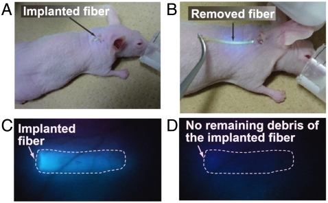
We also removed the implanted fibers after use. The fibers were easily removed from the implantation sites (Fig. 5 and Movie S2). The fluorescent images in Fig. 5 C and D describe that the implanted fibers were removed from the mouse ear with no remaining debris.
Fig. 5.
Removal of the implanted fiber. (A) Fiber implanted in the mouse ear. (B) The implanted fiber was easily removed from the ear. (C) Fluorescent image of the mouse ear before removing the fiber. (D) Fluorescent image of the mouse ear after fiber removal. No fiber debris remains in the mouse ear.
Discussion
Our primary goal was to develop an implantable glucose sensor for minimally invasive, transdermal, and long-term in vivo CGM, thereby preventing diabetic complications and increasing the quality of life for diabetic patients. Previously, we achieved minimally invasive and transdermal in vivo CGM using glucose-responsive fluorescent hydrogel microbeads (10). The microbeads, however, were dislodged and dispersed from the implantation site after one month (see Fig. S2). To develop a sensor that would remain at the implantation site, we employed a fibrous structure. We chemically immobilized the fluorescence sensor to a fiber to increase its contact area with subcutaneous tissue; the increased contact area was designed to decrease the mobility of the subcutaneous implants. We verified our hypothesis by observing that the implanted fibers remained at the implantation site after an extended period (up to 140 d) (see Figs. S3 and S7).
Minimizing inflammation is also an important issue for transdermal, long-term in vivo CGM because inflammation causes (i) interference with transdermal fluorescence transmission (see Fig. S6), (ii) physiological condition changes, and (iii) sensor isolation resulting from fibrous capsules (18–20). To suppress the inflammatory reaction, the sensors must be designed such that they minimize tissue injury, promote tissue recovery, and limit fibrous capsule formation. We successfully minimized inflammation by modifying PAM hydrogel with PEG that resists the adsorption of proteins such as albumin, fibrinogen, and fibronectin; these proteins modulate host inflammatory cell interactions and adhesion (15–17). To further suppress inflammation, anti-inflammatory agents could be encapsulated in hydrogel-based sensors. There have been several reports of the potential of the anti-inflammatory agents for enhancing biocompatibility; these agents including dexamethasone (21) and vascular endothelial growth factor (VEGF) (22) may suppress the inflammation in the tissues surrounding implanted hydrogels. As a result, the functionality of these fibers can be improved even further by encapsulating anti-inflammatory agents within the hydrogel fibers.
The size of the implanted sensors also affects the degree of tissue damage. In this study, the fibers were of approximately 1,000 μm in diameter; the diameter of the fibers can be reduced (down to 500 μm) by polymerizing the hydrogel in smaller microcapillaries. A small diameter ensures not only minimal damage to the tissue but also a high surface-to-volume ratio, thereby enabling a fast response time due to the rapid diffusion of glucose.
For practical in vivo CGM, the fluorescence measurement system should be improved. A pulsed excitation system is required to minimize photobleaching (10) and the potential risks of excessive skin irradiation. If the skin is exposed to the excitation light (405 nm, 5.7 mW·cm-2) for 1 ms every 5 min, this amount of the excitation light exposure is negligible with respect to skin radiation damage and cancer development (23, 24). Moreover, sensor calibration is currently required to correlate the fluorescent signals of the fibers and blood glucose concentrations and determine variations in sensor response depending on implantation depth, skin properties, and physiological condition changes. Consequently, we calibrated the fluorescent signals several times with a precise home blood-concentration monitoring system for one day. A more convenient calibration method is to use a reference fluorescence value; the reference fluorescence allows ratiometric measurement, thereby increasing accuracy and precision. By combining these calibration methods with small and portable fluorescence detectors, a CGM system using fluorescent hydrogel fibers can be a powerful approach for practical in vivo CGM.
Materials and Methods
Fabrication of the Fluorescent Fibers.
The fluorescent hydrogel microfibers were fabricated using adhesion-resistant polyolefin microcapillaries. We first coated the insides of the polyolefin microcapillaries with Pluronic® F127 (Sigma-Aldrich) surfactant to enhance the adhesion-resistance of the microcapillaries (25), allowing easy removal of the microfibers after polymerization. The pregel solution for the PAM hydrogel microfibers contained 5–10 w/v% glucose-responsive fluorescent monomer (10), 15 w/v% acrylamide (AAm) (Wako Pure Chemical Industries Ltd.), 0.3 w/v% N, N′-methylene-bis-(acrylamide) (Bis-AAm) (Wako Pure Chemical Industries Ltd.), and 0.9 w/v% sodium persulfate (SPS) (Kanto Chemical Co. Inc.) in a 60 mM phosphate buffer with 1.0 mM ethylenediaminetetraacetic acid (EDTA) (Nacalai Tesque Inc.), pH 7.4. In addition, the pregel solution for the PEG-bonded PAM hydrogel microfibers contained 1, 5, or 10 w/v% Acryl-PEG (Aldrich). The pregel solution containing N, N, N′, N′-tetramethylethylenediamine (TEMED) (Wako Pure Chemical Industries Ltd.) was flowed into the inner channel of the microcapillaries and then stored at 37 °C. After 30 min, the fluorescent hydrogel microfibers were removed from the microcapillaries. They were then washed with Milli-Q® water for over 48 h to remove unreacted monomers.
Analysis of the Fluorescence Intensity in Vitro and in Vivo.
We inserted the fluorescent hydrogel fibers of 5 mm in a Petri dish with glucose solutions of 500 mg·dL-1 at room temperature. After 20 min, we captured fluorescent images using a fluorescence microscope (SteREO Lumar.V12, Carl Zeiss Inc.) equipped with a video camera (AG-HMC45, Panasonic). To reduce photobleaching, excitation light was applied through a 4% transmissive neutral density filter. Fluorescent images were captured using excitation wavelengths of 350–420 nm and emission wavelengths of 460–520 nm through a filter set (D390/70 and HQ490/60M-2P, CHROMA). The liquid wiped away from the dish using paper. Then we inserted glucose solutions of 250–0 mg·dL-1 to the Petri dish and obtained the fluorescent images of each glucose concentration. The captured images were analyzed using image-processing software (ImageJ).
Inflammation Evaluation and Transdermal Detection over an Extended Period.
We evaluated inflammation and transdermal detection for one month. Inflammation was evaluated based on external changes of mice ears. The inflammation index reflected the sum of reddening, swelling, and scab formation scores. If the ear skin showed reddening, swelling, or scab formation, then the reddening, swelling, and scab formation were scored 1 point for each condition. An inflammation index greater than 1 indicated that the mice ears were inflamed.
We measured the fluorescence intensity of the portions of the mouse ears with and without the fibers. The fluorescence intensity was measured using a fluorescence detector (FLE1000, Nippon Sheet Glass Co. Ltd.). The fluorescence detector can measure at excitation wavelengths of 350–415 nm and emission wavelengths of 450–520 nm. We estimated fluorescence intensity, ΔF, by subtracting the fluorescence intensity of the mice ear skin without the fibers, FB, from the fluorescence intensity of the mice ear skin with the fibers, F. If the fluorescence intensity, ΔF, was greater than 0, the fibers were considered to be transdermally detectable.
In Vivo Glucose Monitoring.
We conducted in vivo glucose monitoring using the protocol described in our previous publication (10); the data are shown in Fig. 4A. Although intravenous glucose challenge stably provides several up-and-down cycles of blood glucose concentrations, surgery inserting tube to vein may induce sample loss. Thus, we injected glucose and insulin into the intraperitoneal cavities of the mice for long-term in vivo glucose monitoring. The protocol for glucose challenge is briefly described as follows: The in vivo glucose response of the fibers was characterized using male mice (BALB/c Slc-mu/mu, nine-week-old) weighing 21–26 g. All mice were maintained in accordance with the policies of the University of Tokyo Institutional Animal Care and Use Committee. We performed tests on eight mice with one or two glucose challenges individually. To temporarily increase or decrease blood glucose concentrations, glucose (50% glucose, Terumo Co.) or insulin (Novolin® R, Novo Nordisk Pharma Ltd.), respectively, were intravenously (Fig. 4A) or intraperitoneally (Fig. 4B and Fig. S7) injected into the mice.
To obtain fluorescent images of the mouse ear, the mouse ear was attached to a flat block. Fluorescent images were obtained every 1 min, and blood glucose concentrations were measured every 5 min using a blood glucose monitoring sensor (Accu-Chek, Roche). The fluorescence intensity was analyzed from the resulting fluorescent images using image-processing software (Image J).
Supplementary Material
Acknowledgments.
We appreciate the valuable advice of Dr. Daiske Kiriya and Dr. Yukiko Tsuda-Matsunaga. We thank Mr. Masayuki Takahashi and Ms. Mayumi Ishizaka for their help with the long-term monitoring. We thank Ms. Yuki Okubo and Ms. Michiru Sato for their assistance with the animal experiments. This work was supported by the New Energy and Industrial Technology Development Organization (NEDO).
Footnotes
The authors declare no conflict of interest.
This article is a PNAS Direct Submission.
This article contains supporting information online at www.pnas.org/lookup/suppl/doi:10.1073/pnas.1104954108/-/DCSupplemental.
References
- 1.Wilson R, Turner APF. Glucose oxidase: An ideal enzyme. Biosens Bioelectron. 1992;7:165–185. [Google Scholar]
- 2.Wang J. Electrochemical glucose biosensors. Chem Rev. 2008;108:814–825. doi: 10.1021/cr068123a. [DOI] [PubMed] [Google Scholar]
- 3.Park S, Boo H, Chung TD. Electrochemical non-enzymatic glucose sensors. Anal Chim Acta. 2006;556:46–57. doi: 10.1016/j.aca.2005.05.080. [DOI] [PubMed] [Google Scholar]
- 4.Kawanishi T, Romey MA, Zhu PC, Holody MZ, Shinkai S. Study of boronic acid based fluorescent glucose sensors. J Fluoresc. 2004;14:499–512. doi: 10.1023/b:jofl.0000039338.16715.48. [DOI] [PubMed] [Google Scholar]
- 5.James TD, Sandanayake KRAS, Shinkai S. Chiral discrimination of monosaccharides using a fluorescent molecular sensor. Nature. 1995;374:345–347. [Google Scholar]
- 6.James TD, Sandanayake KRAS, Shinkai S. Novel photoinduced electron-transfer sensor for saccharides based on the interaction of boronic acid and amine. J Chem Soc Chem Commun. 1994:477–478. [Google Scholar]
- 7.James TD. Saccharide-selective boronic acid based photoinduced electron transfer (PET) fluorescent sensors. Top Curr Chem. 2007;277:107–152. [Google Scholar]
- 8.James TD, Sandanayake KRAS, Iguchi R, Shinkai S. Novel saccharide-photoinduced electron transfer sensors based on the interaction of boronic acid and amine. J Am Chem Soc. 1995;117:8982–8987. [Google Scholar]
- 9.Russell RJ, Pishko MV, Gefrides CC, McShane MJ, Coté G. A fluorescence-based glucose biosensor using concanavalin A and dextran encapsulated in a poly(ethylene glycol) hydrogel. Anal Chem. 1999;71:3126–3132. doi: 10.1021/ac990060r. [DOI] [PubMed] [Google Scholar]
- 10.Shibata H, et al. Injectable hydrogel microbeads for fluorescence-based in vivo continuous glucose monitoring. Proc Natl Acad Sci USA. 2010;107:17894–17898. doi: 10.1073/pnas.1006911107. [DOI] [PMC free article] [PubMed] [Google Scholar]
- 11.Malmsten M, Emoto K, Alstine JMV. Effect of chain density on inhibition of protein adsorption by poly(ethylene glycol) based coatings. J Colloid Interface Sci. 1998;202:507–517. [Google Scholar]
- 12.Trenam CW, Dabbagh AJ, Morris CJ, Blake DR. Skin inflammation induced by reactive oxygen species (ROS): An in vivo model. Br J Dermatol. 1991;125:325–329. doi: 10.1111/j.1365-2133.1991.tb14165.x. [DOI] [PubMed] [Google Scholar]
- 13.Karlsson PC, Hughes R, Rafter JJ, Bruce WR. Polyethylene glycol reduces inflammation and aberrant crypt foci in carcinogen-initiated rats. Cancer Lett. 2005;223:203–209. doi: 10.1016/j.canlet.2004.10.029. [DOI] [PubMed] [Google Scholar]
- 14.Maran A, et al. Continuous subcutaneous glucose monitoring in diabetic patients a multicenter analysis. Diabetes Care. 2002;25:347–352. doi: 10.2337/diacare.25.2.347. [DOI] [PubMed] [Google Scholar]
- 15.Onuki Y, Bhardwaj U, Pharm M, Papadimitrakopoulos F, Burgess DJ. A review of the biocompatibility of implantable devices: Current challenges to overcome foreign body response. J Diabetes Sci Technol. 2008;2:1003–1015. doi: 10.1177/193229680800200610. [DOI] [PMC free article] [PubMed] [Google Scholar]
- 16.Delves PJ, Roitt IM. Advances in immunology: The immune system: First of two parts. N Engl J Med. 2000;343:37–49. doi: 10.1056/NEJM200007063430107. [DOI] [PubMed] [Google Scholar]
- 17.Anderson JM, Rodriguez A, Chang DT. Foreign body reaction to biomaterials. Semin Immunol. 2008;20:86–100. doi: 10.1016/j.smim.2007.11.004. [DOI] [PMC free article] [PubMed] [Google Scholar]
- 18.Elbert DL, Hubbell JA. Surface treatments of polymers for biocompatibility. Annu Rev Mater Sci. 1996;26:365–394. [Google Scholar]
- 19.Lin YS, Hlady V, Gölander C.-G. The surface density gradient of grafted poly(ethylene glycol): Preparation, characterization and protein adsorption. Colloids Surf B Biointerfaces. 1994;3:49–62. doi: 10.1016/0927-7765(93)01114-7. [DOI] [PMC free article] [PubMed] [Google Scholar]
- 20.DeFife KM, Shive MS, Hagen KM, Clapper DL, Anderson JM. Effects of photochemically immobilized polymer coatings on protein adsorption, cell adhesion, and the foreign body reaction to silicone rubber. J Biomed Mater Res. 1999;44:298–307. doi: 10.1002/(sici)1097-4636(19990305)44:3<298::aid-jbm8>3.0.co;2-n. [DOI] [PubMed] [Google Scholar]
- 21.Tsurufuji S, Sugio K, Takemasa F. The role of glucocorticoid receptor and gene expression in the anti-inflammatory action of dexamethasone. Nature. 1979;280:408–410. doi: 10.1038/280408a0. [DOI] [PubMed] [Google Scholar]
- 22.Norton LW, Tegnell E, Toporek SS, Reichert WM. In vitro characterization of vascular endothelial growth factor and dexamethasone releasing hydrogels for implantable probe coatings. Biomaterials. 2005;26:3285–3297. doi: 10.1016/j.biomaterials.2004.07.069. [DOI] [PubMed] [Google Scholar]
- 23.Freeman SE, et al. Wavelength dependence of pyrimidine dimer formation in DNA of human skin irradiated in situ with ultraviolet light. Proc Natl Acad Sci USA. 1989;86:5605–5609. doi: 10.1073/pnas.86.14.5605. [DOI] [PMC free article] [PubMed] [Google Scholar]
- 24.Gruijl FR, et al. Wavelength dependence of skin cancer induction by ultraviolet irradiation of albino hairless mice. Cancer Res. 1993;53:53–60. [PubMed] [Google Scholar]
- 25.Bridgetta MJ, Davies MC, Denyerb SP. Control of staphylococcal adhesion to polystyrene surfaces by polymer surface modification with surfactants. Biomaterials. 1992;13:411–416. doi: 10.1016/0142-9612(92)90159-l. [DOI] [PubMed] [Google Scholar]
Associated Data
This section collects any data citations, data availability statements, or supplementary materials included in this article.


