Abstract
For high dose rate (HDR) brachytherapy, independent treatment verification is needed to ensure that the treatment is performed as per prescription. This study demonstrates dosimetric quality assurance of the HDR brachytherapy using a commercially available two-dimensional ion chamber array called IMatriXX, which has a detector separation of 0.7619 cm. The reference isodose length, step size, and source dwell positional accuracy were verified. A total of 24 dwell positions, which were verified for positional accuracy gave a total error (systematic and random) of –0.45 mm, with a standard deviation of 1.01 mm and maximum error of 1.8 mm. Using a step size of 5 mm, reference isodose length (the length of 100% isodose line) was verified for single and multiple catheters of same and different source loadings. An error ≤1 mm was measured in 57% of tests analyzed. Step size verification for 2, 3, 4, and 5 cm was performed and 70% of the step size errors were below 1 mm, with maximum of 1.2 mm. The step size ≤1 cm could not be verified by the IMatriXX as it could not resolve the peaks in dose profile.
Keywords: 2D array, brachy, IMatriXX
Introduction
The high dose rate (HDR) brachytherapy is a technique where small Iridium-192 source (active length 3.5 mm and diameter 0.6 mm) can be programmed to dwell for a given time at any point in the treatment catheters. The success of this treatment is strongly dependent on accurate knowledge of the source strength, dwell positions, and dwell times.[1] Since the complete treatment may be given in just a few minutes with HDR remote after loading equipment, it is extremely important to perform adequate quality control (QC) checks on the equipment before use.[2] For high-activity source even small dwell times introduce significant errors.[3] Different methods can be adopted to verify these vital factors in HDR brachytherapy. Most of these methods, however, depend on visual inspection of either a radiographic image or a closed circuit television image to quantify the accuracy of HDR unit source positioning.[4] The degree of accuracy and reproducibility of results make quality assurance checks more reliable. This can be achieved if the verification method is capable of resolving minute differences in source position. Most of the currently used quality assurance (QA) tests concentrate on the verification of source position and dwell time. Rickey et al, 2010[1] and Song et al, 2009[5] verified the source position and dwell time with their own designed equipment. However, uses of most of the equipments other than film are limited only to brachytherapy. Furthermore, designing equipment for brachytherapy QA is not practicable or economically viable to all radiotherapy departments. Thus, equipments used in external radiotherapy QA may be tailored for use in brachytherapy. In this study, commercially available detector array IMatriXX was used to verify the dwell position, reference isodose length (length of 100% isodose line in source direction), and step size in comparison with treatment planning system (TPS).
Materials and Methods
All the tests included in this study were performed on two-dimensional, monolithic, large area pixel-segmented ionization chamber (PXC)[6] commercially available as IMatriXX. This device consists of 1020 vented ion chambers each having active volume 0.08 cc, arranged in 32 × 32 grids. The distance between two detectors is 0.7619 cm. When irradiated, the air in the chambers is ionized. The current, which is proportional to the dose rate, is measured and digitalized by a nonmultiplexed 1020 channels current sensitive analog to digital converter. The measured data are transmitted to a Personal Computer via standard Ethernet interface. The signals are analyzed by the OmiPro-I’mRT version 1.7 (IBA, GmBH). First the IMatriXX detector array is calibrated to external beam radiation (6 MV), to get the response of all detectors uniform. Three interstitial flexible catheters were fixed above the IMatriXX detector array such that 300thsource position (distal end) corresponds with the center of the superior most chamber. The distance between the center of first and last detector along the catheters was 23.6 cm. The flexible plastic catheters were placed straight above the flat panel at –5.71, 0.38, and 4.95 cm, respectively, from the central axis as shown in Figure 1. The catheters were placed along the detector line (row wise/column wise) to avoid any systematic shift in the catheter placement, hence in the large systematic error. Flexiplan version 2.6 (Isodose Control B.V.) was used to create plans for this fixed geometry. Plans were created to verify (i) dwell position, (ii) reference isodose length, and (iii) step size. Different source dwell positions were selected for each of these three experiments.
Figure 1.
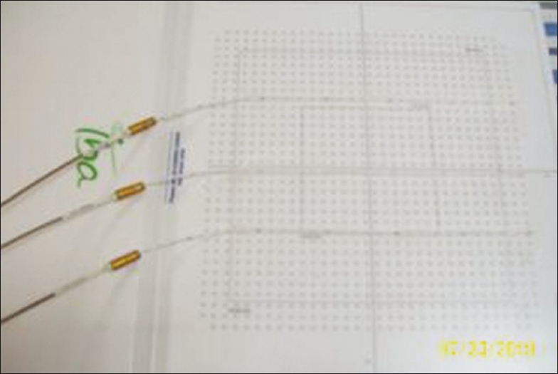
Position of catheters over the detector array
All plans created for this study used 5 mm step size with 2 s dwell time. The dwell time was set as 2 s in all the plans with the reason that the detector response was adequate to resolve the peaks in dose profile, which otherwise resulted in a single dark image. The plans were executed on IMatriXX using Flexitron HDR unit. The dose profiles obtained along the source line at –5.71, 0.38, and 4.95 cm from central axis were analyzed. Each source position was indicated as peak in the profile.
The dwell positions were obtained from analyzed profiles as tabulated in Table 1. The obtained spatial information alone was not adequate to find the reference isodose length. Since the dwell positions were set to 2 s, plans created to verify the reference isodose length were not prescribed to any particular distance. This made the plan to be without prescription. Thus a method was adopted in which a point that is 5 mm superior to the first source position (300th position) was selected [Figure 2], and the dose at this point was normalized to 100%. With reference to this point the reference isodose length was measured as maximum length of 100% isodose along catheter axis [Figure 3]. Treatment plans with different dwell positions were executed, and measured reference isodose length were compared with the TPS calculated values, as tabulated in Tables 2 and 3. The step size was tested for 2, 3, 4, and 5 cm step sizes. The measured peaks helped to verify step sizes.
Table 1.
Comparison of planned and measured dwell positions
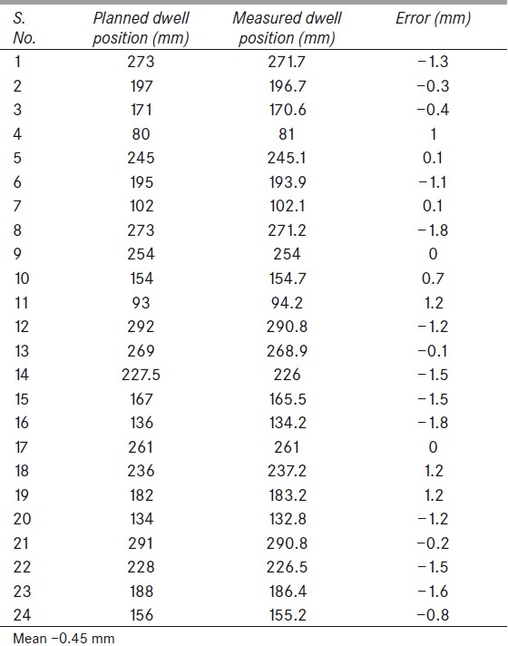
Figure 2.
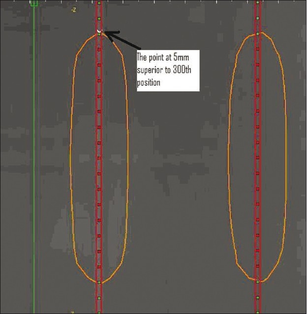
The position of the point where the dose was considered as 100%
Figure 3.
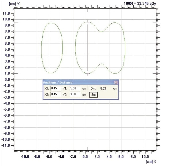
Reference isodose length verification
Table 2.
Reference isodose length verification for same source loading of 7 cm

Table 3.
Reference Isodose length verification for different source loadings

It was not possible to calibrate the detector array for Ir-192 energy as well as brachytherapy (4Π) geometry, thus only relative isodose could be verified.
Results
Dwell position tests
Three random dwell position checks were performed. A total of 24 dwell positions were obtained from three tests. The maximum dwell position error was noted to be 1.8 mm with a mean 0.45±1.99 mm 95% confidence interval. Total error divided as systematic or mean error of –0.45mm and random component error or standard deviation was 1.01 mm [Table 1]. When planned and measured dwell positions were plotted, a linear relationship was obtained [Figure 4].
Figure 4.
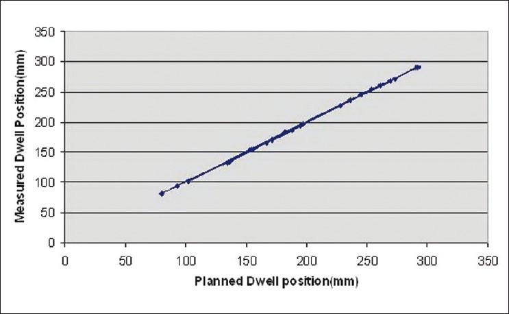
Planned versus measured dwell position
Reference isodose length verification
Three plans were analyzed for reference isodose length verification. Center catheter alone was loaded in the first plan. The source was loaded for 10 cm from 270th source position to 170th source position. The second plan was created with source loading length of 7 cm in all catheters from 270th position as tabulated in table 2. The third plan contained differential source loading at the center and other catheters. The center catheter was loaded from 270th position to 200th position for a length of 7 cm. The other two catheters were loaded only for 3 cm in which the first position started from 170th position, as indicated in table 3. The reference isodose length was measured for each catheter. A total of seven reference isodose lengths in three plans were compared with the TPS planned lengths [Tables 2 and 3]. Less than 1 mm error was found in 57% of the tested reference isodose lengths (maximum error was 1.5 mm). Planned versus measured reference isodose lengths were plotted [Figure 5].
Figure 5.
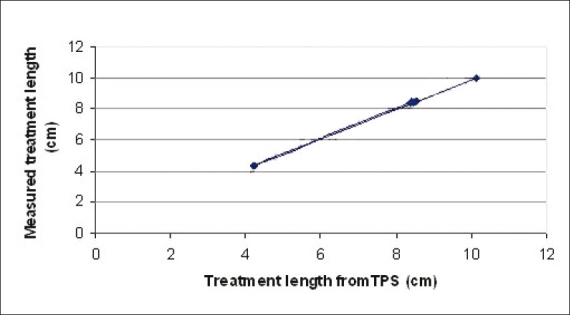
Planned versus measured reference isodose length
Step size verification
Step sizes less than 1 cm were not able to be resolved as peaks with IMatriXX. However, step sizes 2, 3, 4, and 5 cm were verified [Figure 6]. Seventy percent of verified step sizes showed errors <1 mm. Maximum error was 1.2 mm in a plan where the step size was 2 cm.
Figure 6.
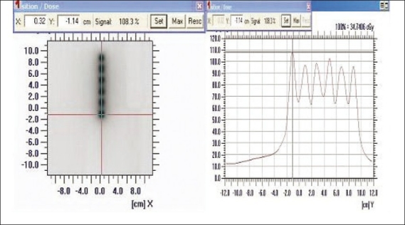
The step size analysis for 2 cm step size
Discussion
PXC was designed for use in external beam dosimetry and to perform two-dimensional verifications of fields with large gradients and complex shapes.[6] One of the limiting factors for this instrument is volume averaging effect due to finite size of the ion chamber, measured to have full width at half maximum of about 5.8 mm, when a Gaussian response function was used.[7] If the volume of the beam data collecting chamber is comparable with that of the IMatriXX chambers then due to similar volume averaging effect, IMatriXX measured values shows a very high degree of match with TPS-calculated values.[7] The IMatriXX measurement also depends on beam modeling in TPS.[7] The literatures can be found for intensity-modulated radiotherapy (IMRT) dose verification by this instrument.[8,9] Generally, the IMRT calculation grid resolution (voxel size) is 2 × 2 × 2 mm and dose distribution is verified with 3% dose difference 3 mm distance to agreement (DTA). Under this scenario comparable results were obtained between IMatriXX and film.[9]
The use of PXC for brachytherapy dosimetry was intended due to two reasons, first its use in dosimetry of high-gradient fields[6] (IMRT dose profile) verification, which is encountered in brachytherapy. Secondly, due to its high charge collection efficiency (0.985) for a dose rate of 3.5 Gy/min[6] of 6 MV photon beam, this dose rate falls under HDR brachytherapy range as indicated by Task Group Report 56[10] (dose rate at 1 cm for 10 Ci source is 6.85 Gy/min). No published literature could be found for Ir-192 energy and brachytherapy geometry for use of PXC.
In this study, all tests performed for dwell position verification resulted with errors <1.8 mm. In order to investigate the spatial resolving efficiency of the detector array, two plans were created with 1 mm dwell position differences; the dwell position in one plan was related with other plan with only 1 mm difference in their value (270th dwell position in one plan corresponds to 269th position in another plan). The step size used in both plans was 5 cm. The plans were executed on IMatriXX and compared. The OmniPro software was able to differentiate the peaks in the dose profile of both plans [Figure 7]. Reference isodose length verification was used to indirectly verify these step sizes to the extent of their agreement with the planned reference isodose lengths in TPS. The mean dwell position variation measured by IMatriXX was smaller than the value 0.7 mm that had been reported by Song et al.[5]
Figure 7.
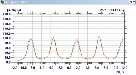
Dose profile of 1 mm shifted dwell positions. It is clear from the graph that peaks were differentiated with each other
For Ir-192 HDR treatments, source position and step sizes are usually verified in clinic by visual inspection by autoradiograph. This autoradiograph is taken as a film by attaching two flexible implant tubes, one having the dummy source and other having the true source as programmed. This method may give rise to systematic as well as random errors. The other disadvantage of film is blurring, as reported by Rickey noneet al[1]; the blurring effect was more pronounced with metal applicators than with plastic catheters. The accuracy of dwell position evaluation in a blur film is subjective and depends on the investigator's and instrument's ability to resolve the peak. This problem was not encountered in IMatriXX since peaks obtained in the dose profile provided the spatial information, which in turn was used to find the dwell positions.
The reproducibility of dwell position measurement using IMatriXX was appreciable; (it measured the dwell position accuracy –0.45 ± 1.99 mm with 95% confidence interval). IMatriXX was able to measure the reference isodose lengths with 2 mm accuracy against TPS calculated values. The reference isodose length of the central catheter was expected to be more than that of other catheters as given in TPS. This is because dose distribution against central catheter will have a contribution from each of the lateral catheters, whereas the lateral two catheters will have contribution only from the central catheter because of the large distance between them (~10.5 cm). IMatriXX was able to quantify the same nature of isodoses and mimic the TPS values.
Conclusions
The flat panel 2D ion chamber array was used in this study. The mean dwell positional accuracy measured was –0.45 mm, with a standard deviation of 1.01 mm (maximum error of 1.8 mm). This is clearly below the tolerance limit of ±2 mm.[10] Until the completion of this study, only one other report describing brachytherapy QA using a prototype flat panel detector with GafChromic film was found.[1] The commercially available flat panel detector IMatriXX proved to be an effective tool in measuring important parameters in brachytherapy. These promising results build a foundation on which further investigations in brachytherapy routine QA can be achieved in future.
Footnotes
Source of Support: Nil.
Conflict of Interest: None declared.
References
- 1.Rickey DW, Sasaki D, Bews J. A quality assurance tool for high-dose-rate Brachytherapy. Med Phys. 2010;37:2525–32. doi: 10.1118/1.3425786. [DOI] [PubMed] [Google Scholar]
- 2.Aldrich JE, Samant SS. An integrated phantom for HDR quality control. Br J Radiol. 1993;66:363–5. doi: 10.1259/0007-1285-66-784-363. [DOI] [PubMed] [Google Scholar]
- 3.Sahoo N. Measurement of transit time of a remote after-loading high dose rate brachytherapy source. Med Phys. 2001;28:1786–90. doi: 10.1118/1.1386779. [DOI] [PubMed] [Google Scholar]
- 4.Zuofeng LI, Thomas PM, Palta JR, Liu C. A quality assurance test tool for high dose-rate remote after loading brachytherapy units. Med Phys. 1998;25:232–5. doi: 10.1118/1.598185. [DOI] [PubMed] [Google Scholar]
- 5.Song H, Bowsher J, Das S, Yin FF. Tracking brachytherapy sources using emission imaging with one flat panel detector. Med Phys. 2009;36:1109–11. doi: 10.1118/1.3081402. [DOI] [PubMed] [Google Scholar]
- 6.Amerio S, Boriano A, Bourhaleb F, Cirio R, Donetti M, Fidanzio A, et al. Dosimetric characterization of a large area pixel-segmented ionization chamber. Med Phys. 2004;31:414–20. doi: 10.1118/1.1639992. [DOI] [PubMed] [Google Scholar]
- 7.Jonathan G, Li, Yan G, Liu C. Comparison of two commercial detector arrays for IMRT quality assurance. J Appl Clin Med Phys. 2009;10:62–74. doi: 10.1120/jacmp.v10i2.2942. [DOI] [PMC free article] [PubMed] [Google Scholar]
- 8.Herzen J, Todorovic M, Cremers F, Platz V, Albers D, Bartels A, et al. Dosimetric evaluation of a 2D pixel ionization chamber for implementa-tion in clinical routine. Phys Med Biol. 2007;52:1197–208. doi: 10.1088/0031-9155/52/4/023. [DOI] [PubMed] [Google Scholar]
- 9.Varatharaj C, Ravikumar M, Sathian S, Supe S, Vivek TR, Manikandan A. Dosimetric verification of brain and head and neck intensity modulated radiation therapy treatment using EDR2 film and 2D ion chamber array matrix. J Cancer Res Ther. 2010;6:179–84. doi: 10.4103/0973-1482.65233. [DOI] [PubMed] [Google Scholar]
- 10.Nath R, Anderson LL, Meli JA, Olch AJ, Stitt JA, Williamson JF. Code of practice for brachytherapy physics.Report of the AAPM Radiation Therapy Committee Task Group No. 56. Med Phys. 1997;24:1557–98. doi: 10.1118/1.597966. [DOI] [PubMed] [Google Scholar]


