Abstract
In situ nanoindentation was performed on a multilayer of poly(acrylic acid) and a high molecular weight, pendant chain polyviologen under controlled electrochemical potential. The modulus of the thin film of polyelectrolyte complex was reversibly modulated, by about an order of magnitude, upon changing the state of charge within the material using the electrochemically active and addressable viologen repeat units. The applied potential, under aqueous conditions, is believed to control the extent of crosslink formation. Simultaneous quartz crystal microbalance measurements revealed the flux of ions into or out of the multilayer during redox cycling. Apparent film modulus also depends on the identity of the last layer.
Keywords: stimuli-responsive materials, actuators, polymeric materials, thin films, biomedical applications, layer by layer, LbL
Introduction
Due to their high sensitivity and quick response, polymer based thin films have evolved as the major material for stimuli responsive materials and devices.1, 2, 3 An extremely versatile avenue to such films is the layer-by-layer deposition of polyelectrolytes, yielding polyelectrolyte multilayers (PEMUs).4 The thickness and composition of these films can be tuned on a nanometer scale, and the possibilities to control film and surface properties and to incorporate biologically active moieties have made them attractive for applications in the biomedical field.5, 6 For example, control of the mechanical properties of thin films are of interest because of the recent focus on the response of cells to substrate stiffness,7 which can dictate whether a cell adheres8, how it moves,9 the eventual phenotype10, and the way in which stem cells differentiate.11 PEMUs are inherently responsive to salt concentration,12 to pH (if weak polyacids or bases are used),13 and in some cases to temperature.14 By including appropriate functional groups in the polymers, or into the PEMU, films responsive to light,15, 16 electrochemical potential,17 temperature,18, 19 mechanical stretching,20, 21 or the presence of biologically active molecules22 have been produced.
PEMUs in contact with aqueous solutions are entangled networks of polyelectrolyte chains swollen with water and doped with small ions.23 Their mechanical properties depend on the interplay of hydration, polymer type, and density of ionic crosslinks. Salt concentration23 and pH13 of the surrounding medium can be used to alter the mechanical properties by changing the number of ionic crosslinks, and the osmotic pressure (water content). Because such stimulii require changing the solution in contact with the film, they are not suitable for biological applications, where ionic strength and pH are fixed. An alternative approach depends on controlling the degree of swelling within the PEMU by changing the redox state of counterions,24, 25 or film components,26 which leads to a net change of counterions and water content27. We were interested in reversible control of crosslinks within a PEMU. Covalent crosslinking, long known to strongly influence the properties of polymers28, 29 and gels 30 is a convenient way to increase the stiffness of PEMUs,16, 31, 10, 32 but is not reversible and often cannot be performed in vivo. Here, we describe an all-polyelectrolyte system that allows one to change the number of charges on one of the polyelectrolytes in the film by applying an electrrochemical potential, which leads to reversible crosslinking changes accompanied by large shifts in PEMU modulus: duravoltammetry (“dura” – relating to stiffness).
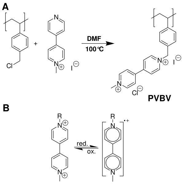
Polyviologens, which we previously showed to have reversible electrochemical response in PEMUs,33 were used as redox active polyelectrolytes. Viologens (N-N′-dialkyl 4-4′-bipyridinium salts) have two positive charges in their oxidized form, which are lost in two successive reduction steps.34, 35 Only the first of these (Scheme 1) is completely reversible. The strong color changes during redox cycling of polyviologen PEMUs,17 have been employed in electrochromic devices.36, 37
Scheme 1.
A, Synthesis of poly(vinyl benzyl viologen) (PVBV); B, Viologen redox chemistry.
Experimental Section
Materials
4,4′-bipyridine (Sigma-Aldrich, 98 %), methyl iodide (Sigma-Aldrich, 99.5 %), chloroform (Alfa Aesar, stabilized with amylenes, >99.5 %), dimethylformamide (Sigma-Aldrich, anhydrous, 99.8 %), ethyl acetate (Fisher Scientific, HPLC grade), methanol (Malinckrodt, anhydrous, 99.9 %), poly(p-vinyl benzyl chloride) (PVBCl, Scientific Polymer Products, Mw 127,900 g/mol), poly(ethyleneimine) (PEI, Sigma-Aldrich), poly(acrylic acid) (PAA, Sigma-Aldrich, Mw 100,000 g/mol, 35 wt% in water), Trisma base (Fisher Scientific, molecular biology grade), and sodium chloride (EMD, >99 %) were used as received. 18MOhm Milli-Q water was used throughout.
Synthesis
N-methyl bipyridine
5 g (32 mmol) of 4,4′-bipyridine were placed in a 3 neck flask under nitrogen and dissolved in 170 mL of chloroform. After addition of 10 mL (160 mmol, 5 eq) of methyl iodide the mixture was stirred for 70 h at room temperature. The precipitate was then filtered off, washed excessively with chloroform, recrystallized twice from ethanol and dried under vacuum, yielding 5.6 g of a yellow powder (yield: 58 %). 1H-NMR (400 MHz, D2O, δ): 8.95 (2 H, d, CH3N+(CH)2), 8.74 (2 H, d, N(CH)2), 8.42 (2 H, d, CH3N+(CH)2(CH)2C), 7.91 (2 H, d, C(CH)2(CH)2N), 4.38 (3 H, s, CH3).
Poly(vinyl benzyl methyl viologen) (PVBV) was synthesized by adding 1.3 eq. of methyl bipyridine (synthesized by reaction of 4,4′-bipyridine with methyl iodide) to poly(vinyl benzyl chloride) (0.8 g, 5.2 mmol, Scientific Polymer Products) in DMF (120 mL, Sigma-Aldrich, anhydrous, 99.8 %) and heating to 100 °C for 4 h under nitrogen. Precipitation and two reprecitations from methanol in ethyl acetate yielded 1.8 g of a deep red powder after vacuum drying. The degree of substitution as determined by 1H-NMR was about 95 %. 1H NMR (400 MHz, D2O, δ): 9.47 (CH3N+(CH)2), 9.26 (CH2N+(CH)2), 8.80 (N+(CH)2(CH)2C), 7.31 (C(CH)2(CH)2C), 6.66 (C(CH)2(CH)2C), 6.06 (N+CH2C), 4.55 (CH3), 1.69 (br, CHCH2). 13C NMR (100 MHz, D2O, δ) : 150.0 (CCHCH2), 149.3 (CC), 148.0 (CC), 146.4 (CHN), 145.4 (CHN), 131–128 (br, CCHCHC), 127.5 (CHCHN), 126.9 (CHCHN), 125.4 (CCH2), 64.3 (CH2N), 48.8 (CH3), 45-40 (br, CHCH2), 27.7 (CH2OH).
Multilayer build-up
Three kinds of substrates were used for multilayer build-up: The platinum electrode for electrochemistry was polished, sonicated and rinsed with water. For AFM measurements, glass disks were cleaned with air plasma then a 5 nm thick chromium layer followed by a 150 nm thick gold layer, 2.5 cm in diameter, were evaporated. Gold coated quartz crystals and AFM substrates were cleaned in an air plasma for 1 min before multilayer coating.
Poly(ethyleneimine) (PEI, Sigma-Aldrich) was 1 mg/mL in 0.25 M NaCl, poly(acrylic acid) (PAA, Sigma-Aldrich, Mw 100,000 g/mol) was 10 mM in tris buffer (Fisher Scientific, 10 mM, pH 7.4, ionic strength adjusted to 0.15 M with NaCl), PVBV was 5 mM in the same buffer. The pH was maintained at 7.4. The platinum electrode and the substrate for AFM measurements were coated by dipping them in the corresponding solutions, the QCM crystals were coated directly in the flow cell of the QCM apparatus. In all cases the substrates were first immersed in the PEI solution followed by rinsing with water for 3 min. Contact time with the PAA and PVBV solutions were 5 min followed by rinsing for 3 min with the Tris buffer.
Electrochemistry
A Pine Wavenow potentiostat was used throughout this work. All experiments were performed in 0.15 M NaCl. The electrolyte solutions were deoxygenated by bubbling with argon. The coated electrodes were employed as working electrodes. Temperature was maintained at 25 °C in all cases. QCM measurements were performed in situ during CV scans from 0 to −0.55 V at a rate of 0.5 mV/s. Changes between potentials in AFM were performed at a rate of 5 mV/s, with an overall scan rate of about 0.1 mV/s.
Quartz crystal microbalance (QCM) was performed on an E4 from Q-Sense using gold coated QCM crystals with a nominal resonance frequency of 4.95 MHz (Q-Sense). The build-up of the PEMUs was observed in situ using the standard flow module. A viscoelastic model55 was used to obtain the thickness of the adsorbed layer from the frequency and dissipation data, assuming a density of 1.2 g/cm3. The coated crystals were then transferred to the electrochemistry module, where the change of frequency and dissipation on application of an electrical potential were monitored.
Atomic force miscropy (AFM) Recording
AFM experiments were performed on a MFP-3D unit, ARC2 Controller (Asylum Research Inc., Santa Barbara, CA) and Igor Pro software (Wavemetrics, Lake Oswego, OR). All measurements including the calibrations were performed in the electrochemistry cell. An AC240-TS silicon probe (Olympus Probes Inc.) was used. The probe was a 240 μm long, 30 μm wide, and 2 μm thick cantilever with a spring constant of around 2 N/m and a resonance frequency of around 70 kHz. The radius of the tip was about 9 nm and its half angle about 18°. The spring constant of each probe was calibrated in air using the thermal fluctuation method38, 39 after calibration of its optical lever sensitivity (OLS). After immersion of the tip in the NaCl solution, the OLS was recalibrated on an uncoated electrode. Force maps were acquired first on an uncoated electrode. On the PEMUs 20 force curves were collected at different locations before applying a potential and at each potential step, after letting the system equilibrate for 1 min. Measurements were performed by decreasing the potential stepwise from 0 to −0.55 V and then increasing it again stepwise to 0 V with continuously applied potential. The distance from the surface for the force curves was set to 1 μm. The velocity of the tip in the z-direction was maintained at 0.5 μm/sec. Data points were collected at a rate of 5 kHz. While the pH was not buffered for the in situ electrochemistry it was measured before and after cycling and remained at about 7.
In addition, AFM images of the films before applying a potential, at the most negative potential, and after one or several cycles were recorded.
Fitting and Analysis
Analysis of the data was also performed using Igor Pro software. The indentation was obtained from the distance of the tip relative to the surface z (the point of contact, determined here as the point at which the deflection versus distance curve deviates from zero, is set to 0) and the tip deflection (Eq. 1). The force and hence the corresponding force curves are obtained by multiplying the deflection with the measured force constant of the tip (Eq. 2). The force curves are then analyzed using models based on Hertzian contact mechanics40, 41, 42, developed for the indentation of a semifinite substrate with a hard indenter. Only the approach part of the force curves corresponding to an indentation of 10 % of the film thickness was analyzed, in order to avoid convolution of the mechanical properties of film and substrate43. Eqs. 3 to 5 give the dependence of the applied force on the distance and substrate modulus for different geometries of the indenter.
| (1) |
| (2) |
| (3) |
| (4) |
| (5) |
Where R is the radius of the sphere or the punch; α is the half angle of the cone; z is the distance of the tip relative to the surface in the z-direction; K is the spring constant of the cantilever in use; d is the deflection of the tip, and υ is the Poisson ratio of the material.
Though the AFM tips used here are conical in shape, the decision which model to use is not evident. The sphere model describes the indentation of a soft flat material by a hard sphere of radius much bigger than the indentation40. This is obviously not the case here for tips with radii of less than 10 nm and indentations larger than 30 nm. The model for a cone shaped indenter ideally requires its apex to be infinitely sharp41. Depending on the interaction with the material, the indenter can hence behave like a real cone or like a thin punch. The three models have different power dependencies on the indentation: 1, 1.5, and 2 for the punch, sphere and cone model respectively, resulting in different force-displacement profiles. The decision between cone and punch model for fitting was made by comparing the fits using the known geometrical parameters of the tips (half angle of 18° for the cone model and radius of 9 nm for the punch model). Softer surfaces were usually in better agreement with the cone model, stiffer ones with the punch model. At the conditions, where a change from one to the other was observed for a given surface, the two were in good agreement.
When the corresponding model was used, the fitted data yielded the fit parameter EC that relates the compliance of the indenter to the compliance of the indentee. EC can be deconvoluted into Young's modulus values using Eq. 6 where EC, the fit parameter for the corresponding model, is directly related to
| (6) |
the Young's modulus and Poisson ratio of the indenter material are E1 and υ1 respectively; those for the indented material are and E2 and υ2, in our case, a silicon cantilever. The value of E2 was set to 150 GPa and υ2 was set at 0.27 for silicon. The PEMUs were considered to be perfectly elastic in the range of applied forces, so υ1 was set to 0.5. Force curves were offset in the x and y directions to set the contact point to zero force and zero distance. The fit was performed in the range 0 to 25, 40, and 50 nm for 13, 15, and 16 layer films respectively.
Results and Discussion
A common route to viologen containing polyelectrolytes is polycondensation of bipyridine with various α,ω-alkyl dihalogenides.44 However, reaching high molecular weights is difficult45 (for example, purification by dialysis leads to extensive loss of material17). To maintain high molecular weight starting materials we chose the modification route,46 starting with poly(p-vinyl benzyl chloride) having a Mw of 127,900 ± 600 g/mol and a Mw/Mn of 1.62 as precursor polymer. Treating the starting polymer with mono-methyl bipyridinium in DMF at 100 °C for 4 h yielded the desired polymer, poly(p-vinyl benzyl viologen) (PVBV, Scheme 1), Mw = 292,400 g mol-1 with about 95 % of the monomer units bearing viologen groups in reasonable yield (82 %).
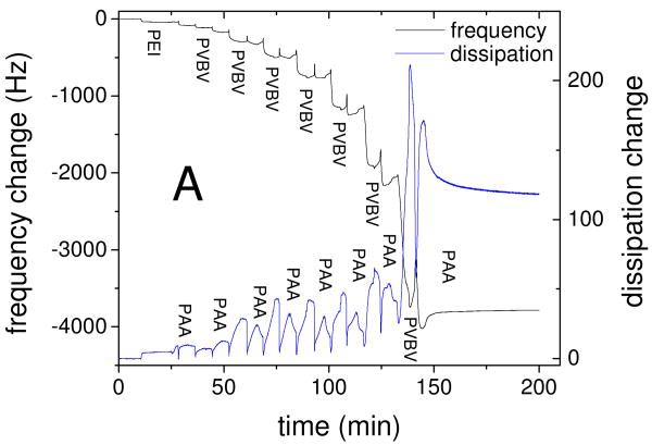
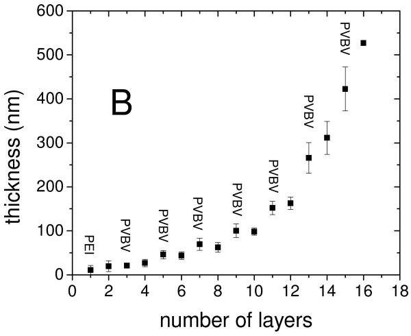
The ideal stimuli-responsive film should have sufficient thickness and low surface roughness to allow for convenient measurement of the mechanical properties, and a strong change of properties upon application of a potential. Poly(acrylic acid) (PAA)/PVBV PEMUs assembled in Tris buffer at pH 7.4 with 0.15 M NaCl were found to be well suited for this purpose. The thickness of the hydrated PAA/PVBV films, studied by quartz crystal microbalance (QCM), increased “exponentially” with the number of layers (Fig. 1), as is often observed for multilayers built with PAA.6 Exponentially growing PEMUs are strongly hydrated, show high mobility of at least one of the polyelectrolytes,48 and are intrinsically nonstoichimetric, as the growth mechamism requires excess of one of the polyelectrolytes throughout the whole film.49 On adsorption of a PAA layer the dissipation decreased relative to the previous PVBV layer, indicating a stiffer film, while the frequency only changed slightly (Fig. 1). A 13 layer PAA/PVBV PEMU had a hydrated thickness of nearly 300 nm, suitable for measuring its mechanical properties by nano-indentation; 15 and 16 layer films had thicknesses of 420 and 530 nm, respectively. The rms roughness of these films in their hydrated form was 9 nm for a 1 μm2 area of a 15-layer film (SI Fig. S1).
Figure 1.
Build up of PEI(PAA/PVBV) PEMUs studied by QCM. A: Frequency and dissipation change of the 3rd harmonic during build up of a 16 layer PEMU. B: Thickness of the hydrated film versus number of layers as obtained from the QCM data using a viscoelastic model47. The larger thickness steps with PVBV are consistent with an excess of PVBV charge in the multilayer.
The electrochemical behavior of these multilayers is dominated by peaks corresponding to the reduction and oxidation of the viologen groups centered around E°′= −0.50 V vs. SCE (Fig. 2). As the second reduction step of viologens is not entirely reversible, the scan range was limited to address only the first reduction step. The shape of the voltammograms is consistent with a reversible, surface-bound species. The appropriate color changes were observed.37
Figure 2.
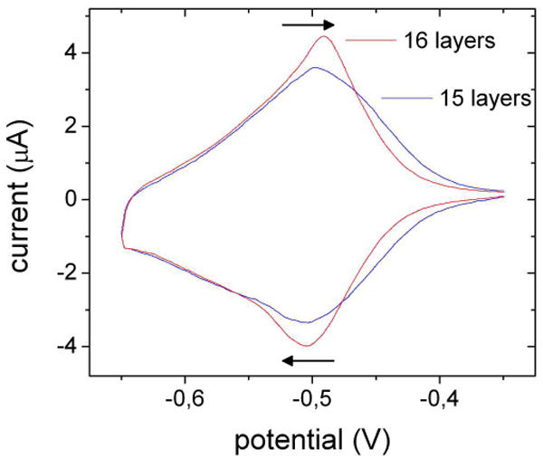
Cyclic voltammetry of a PEI(PAA/PVBV)7 (15 layers) and a PEI(PAA/PVBV)7PAA (16 layer) PEMU on a Pt electrode in 0.15 M NaCl against SCE. Scan rate: 2 mV s-1.
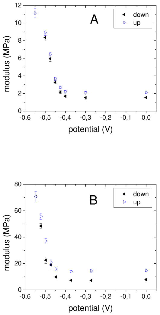
In situ AFM nano indentation experiments50 were conducted to study the influence of the reduction of the viologen groups on the mechanical properties of these films. Multilayers were built on a glass disk coated with a gold electrode that served as the bottom of a liquid cell. Platinum foil and Ag/AgCl were respective counter and reference electrodes. The supporting electrolyte was 0.15 M NaCl. Although CV scans were run to -0.65V, reproducible and reversible nanoindentation was observed by maintaining the applied potential more positive than -0.55 V to limit excess extrinsic charge (compensated by counterions), known to destabilize PEMUs.51, 52, 53 The potential was decreased stepwise from 0 to −0.55 V, then increased back to 0V. At each step, 20 force curves were recorded at different spots on the film. The approach part of the force curves up to an indentation corresponding to 10 % of the film thickness was used to determine the apparent modulus of the film using models based on Hertzian contact mechanics (references 10, 50). With decreasing potential the slope of the force curves became steeper (SI Fig. S2). This corresponds to an increase of the apparent modulus of the films as shown in Fig. 3. The actual values depended on the number of layers and especially on the identity of the last, or “top,” layer. Films with 15, 16, and 13 layers, terminated, respectively, by PVBV, PAA, and PVBV were studied in detail. The initial modulus at 0 V increased in the order 15 layers, 1.5 MPa; 13 layers, 6.8 MPa; 16 layers, 7.3 MPa. The difference between 13 and 15 layers can be explained by an increase in PEMU nonstoichiometry, as reflected also by the “exponential” growth regime of these films. On the other hand, PAA as the last layer exerted a stiffening effect.
Figure 3.
Apparent modulus of PAA/PVBV PEMUs versus potential measured by AFM nanoindentation in 0.15 M NaCl. “Scans” were performed downwards from 0.0 V to – 0.55 V (◂) and then upwards (Δ) to obtain “cyclic duravoltammograms.” A: 15 layers, B: 16 layers.
The in situ modulus increased slightly from 0.0 V to – 0.4 V, then steeply. At −0.55 V, moduli of 11, 32 and 71 MPa, respectively for the 15, 13 and 16 layer films, were measured. This corresponds to a respective increase of the stiffness by a factor of 7.3, 4.7, and 9.7. The lower increase of the stiffness for the 13 layer system is probably due to the lower total number of viologen groups in this thinner film. The stiffening was reversible, and increasing the potential again to 0 V lead to a softening of the film. No major change in the responsive properties was observed over several cycles (SI Fig. S4). The modulus changed nearly linearly with the percentage of reduced viologen groups (SI Fig. S5). No significant change of the topography of the PEMUs occurred upon application of a potential ramp (SI Fig. S1). Films have about the same modulus at the starting potential (0.0 V) as they had before electrochemical treatment. Thus, the composition at 0.0 V is assumed to be the same as that of the nascent, or as-prepared, multilayer.
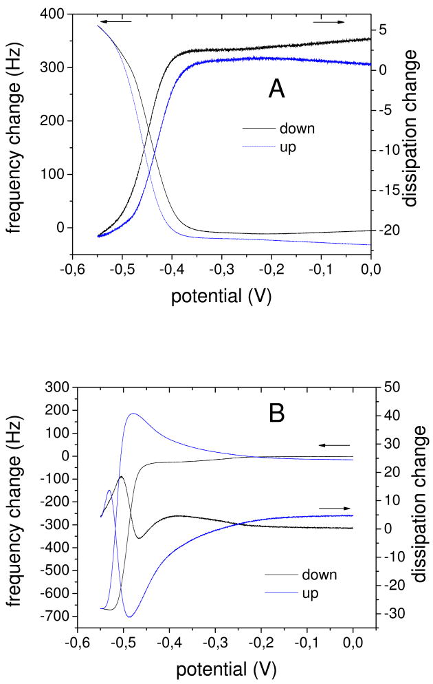
The reduction of the viologen groups leads to the loss of positive charges inside the film. As the film does not decompose, and hence no polyelectrolytes are lost, charge compensation must be achieved either by bringing sodium ions into the film or by liberating chloride ions into solution, or a combination of both. To gain more insight into the dynamics of charge inside the PEMU, cyclic voltammetry was performed in situ in a quartz crystal microbalance. The PAA/PVBV multilayers were assembled on the gold surface of the crystal, which also served as the working electrode. On reduction, the resonance frequency increased, while the dissipation decreased, for 15 layer PEMUs terminated with PVBV (Fig. 4A). A detailed analysis of the QCM data using a viscoelastic model showed that this corresponds to a decrease of the thickness of the film (and also of its mass), as observed for viologen containing polyelectrolyte complexes,54 and an increase of its stiffness (see Figures S7 and S8 in the Supporting Information). The maximum change in resonance frequency corresponds to a decrease of the thickness by about 15 %. As is typical for QCM, a mass gain(loss) reflects a net influx(outflow) of ions it is, however, reasonable to assume net water flux flows in the same direction as net ion flux. Charge compensation in the 15 layer system is hence achieved by anion outflow. Both stiffness and mass changes are reversed when the PEMU is reoxidized.
Figure 4.
QCM electrochemistry on a 15 layer PEMU (PEI(PAA/PVBV)7), upper panel, and 16 layer (PEI(PAA/PVBV)7PAA), lower panel, PEMU. Shown are the frequency and dissipation changes of the 3rd harmonic versus potential. The scan rate is 0.5 mV/s. Potentials versus SCE.
For the 16 layer PEMU terminated with the polyanion PAA the QCM response was different (Fig. 4B). An initial strong decrease of the resonance frequency and a complex response, including an increase, of the dissipation was followed by an increase of the resonance frequency and a decrease of the dissipation. This indicates that charge compensation is first achieved by cation influx, and changes at some point to anion (and cation) outflow. Analysis of the data for the 16 layer system using a viscoelastic model55 indicates that the initial response effectively corresponds to an increase of the thickness of the film (SI Fig. S9), and that this is also accompanied by an increase of the modulus (i.e. stiffening, SI Fig. S10). The complex response in Fig. 4b suggests at least two processes are occurring together under kinetic control. The fact that this was only observed in systems terminated with a polyanion layer (14-layer films behaved similar to 16-layer films and 13-layer films (SI Fig. S11) behaved similar to 15-layer films) suggests that surface charge plays an important role in ion flux. We assume that the negative excess charge at the film surface in the case of the 16-layer system hinders outflow of anions, which results in charge compensation by cation influx and hence to an increase of the osmotic pressure in the film and so to the observed swelling. At some point the swelling of the film and the influx of cations decrease the effect of the surface charge making the outflow of anions and cations possible. This leads then to a deswelling of the film. Both frequency and dissipation return to their original values after voltage cycling. The kinetic complexity inferred from Fig. 4b is not observed in the AFM measurements because the timescale of the “scans” in the nanoindentation are much longer.
The data in Fig. 3 show a strong, reversible, change in modulus with extent of reduction for both PAA and PVBV terminated multilayers. Increase of the modulus of a polymeric network is associated with an increase of the density of effective crosslinks.56 However, the stiffening mechanisms for 15- and 16–layer films appear to be quite different. Fig 4A shows that the 15-layer PEMU loses mass as it stiffens. Fig. 5 shows two possible mechanisms for increased modulus with mass loss: a) formation of an ion pair crosslink with loss of ions. b) formation of a viologen dimer crosslink and loss of ions. Viologen radical cations are known to form ion pairs, especially at high concentration (as found within the multilayer).34, 57
Figure 5.
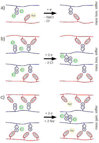
Possible mechanism of stiffening by a) formation of an ion crosslink through outflow of ions, leading to mass loss; b) formation of a viologen radical dimer, leading to loss of chloride ions and mass loss; and c) formation of a violgen radical dimer, with influx of sodium ions and mass gain.
The PAA-terminated 16 layer film showed a mass gain and a complex stiffening response when reduced. Mass gain with stiffening can be accomplished via a mechanism shown in Fig. 5c, which again invokes viologen radical cation dimerization. Taken together these results suggest that the stiffening is largely due to the formation of crosslinks by dimerization of viologen radical cations. Detailed studies of this mechanism using spectroelectrochemical methods will be reported in the future.
The parameters and changes deduced from the QCM viscoelastic modeling are of the same magnitude and direction as those from nanoindentation, but are taken over a much higher frequency range. Variable frequency measurements of PEMU modulus show a strong viscous component, which attenuates at higher frequency.58 Thickness data become more realiable for stiffer films. Changes in hydration probably account for a minor portion of the modulus change, as more hydrated films are expected to be softer. However, the dimensional changes were rather small here – insufficient to account for the large swings in modulus. Futhermore, films that became thinner (less hydrated) on reduction, such as the 15-layer PEMU, or thicker (more hydrated), i.e. the 16 layer PEMU, both became stiffer.
Conclusion
In conclusion, these thin films allow the reversible, repeated, and controlled switching of their mechanical properties by nearly one order of magnitude. By varying the number of layers and the last layer the total range of moduli accessible reaches nearly two orders of magnitude. In situ microbalance measurements reveal some complexity in the flow of ions into and out of the multilayers as they are electrochemically cycled. These PEMUs are possible platforms for the study of cell response to the mechanical properties of the substrate in situ, which studies are underway.
Supplementary Material
Acknowledgments
The authors gratefully acknowledge support from the National Institutes of Health (grant number RO1 EB006158) and the National Science Foundation (grant DMR-0939850).
Footnotes
Supporting Information Available. Topography of the surfaces at different electrochemical potentials as determined by AFM; force curves recorded at different electrochemical potentials; modulus vs electrochemical potential for 13 layer PEMUs; consecutive AFM-electrochemistry cycles for 15 layer PEMUs; QCM-electrochemistry data for a 13 layer PEMU.
References
- 1.Roy D, Cambre JN, Sumerlin BS. Progr Polym Sci. 2010;35:278. [Google Scholar]
- 2.Tokarev I, Motornov M, Minko S. J Mater Chem. 2009;19:6932. [Google Scholar]
- 3.Stuart MAC, Huck WTS, Genzer J, Muller M, Ober C, Stamm M, Sukhorukov GB, Szleifer I, Tsukruk VV, Urban M, Winnik F, Zauscher S, Luzinov I, Minko S. Nat Mater. 2010;9:101. doi: 10.1038/nmat2614. [DOI] [PubMed] [Google Scholar]
- 4.Decher G. Science. 1997;277:1232. [Google Scholar]
- 5.Tang ZY, Wang Y, Podsiadlo P, Kotov NA. Adv Mater. 2006;18:3203. [Google Scholar]
- 6.Boudou T, Crouzier T, Ren KF, Blin G, Picart C. Adv Mater. 2010;22:441. doi: 10.1002/adma.200901327. [DOI] [PubMed] [Google Scholar]
- 7.Discher DE, Janmey P, Wang YL. Science. 2005;310:1139. doi: 10.1126/science.1116995. [DOI] [PubMed] [Google Scholar]
- 8.Thompson MT, Berg MC, Tobias IS, Rubner MF, Van Vliet KJ. Biomaterials. 2005;26:6836. doi: 10.1016/j.biomaterials.2005.05.003. [DOI] [PubMed] [Google Scholar]
- 9.Pelham RJ, Wang YL. Proc Natl Acad Sci USA. 1997;94:13661. doi: 10.1073/pnas.94.25.13661. [DOI] [PMC free article] [PubMed] [Google Scholar]
- 10.Moussallem MD, Olenych SG, Scott SL, Keller TCS, III, Schlenoff JB. Biomacromolecules. 2009;10 doi: 10.1021/bm9007309. [DOI] [PMC free article] [PubMed] [Google Scholar]
- 11.Engler AJ, Sen S, Sweeney HL, Discher DE. Cell. 2006;126:677. doi: 10.1016/j.cell.2006.06.044. [DOI] [PubMed] [Google Scholar]
- 12.Dubas ST, Schlenoff JB. Langmuir. 2001;17:7725. [Google Scholar]
- 13.Hiller J, Rubner MF. Macromolecules. 2003;36:4078. [Google Scholar]
- 14.Mueller R, Kohler K, Weinkamer R, Sukhorukov G, Fery A. Macromolecules. 2005;38:9766. [Google Scholar]
- 15.Saremi F, Tieke B. Adv Mater. 1998;10:388. [Google Scholar]
- 16.Vazquez CP, Boudou T, Dulong V, Nicolas C, Picart C, Glinel K. Langmuir. 2009;25:3556. doi: 10.1021/la803577t. [DOI] [PubMed] [Google Scholar]
- 17.Laurent D, Schlenoff JB. Langmuir. 1997;13:1552. [Google Scholar]
- 18.Glinel K, Sukhorukov GB, Mohwald H, Khrenov V, Tauer K. Macromol Chem Phys. 2003;204:1784. [Google Scholar]
- 19.Jaber JA, Schlenoff JB. Macromolecules. 2005;38:1300. [Google Scholar]
- 20.Mertz D, Vogt C, Hemmerle J, Mutterer J, Ball V, Voegel JC, Schaaf P, Lavalle P. Nat Mater. 2009;8:731. doi: 10.1038/nmat2504. [DOI] [PubMed] [Google Scholar]
- 21.Reisch A, Hemmerle J, Chassepot A, Lefort M, Benkirane-Jessel N, Candolfi E, Mesini P, Letscher-Bru V, Voegel JC, Schaaf P. Soft Matter. 6:1503. [Google Scholar]
- 22.Serizawa T, Yamaguchi M, Akashi M. Angew Chem. 2003;115:1147. doi: 10.1002/anie.200390293. [DOI] [PubMed] [Google Scholar]
- 23.Jaber JA, Schlenoff JB. J Am Chem Soc. 2006;128:2940. doi: 10.1021/ja055892n. [DOI] [PubMed] [Google Scholar]
- 24.Grieshaber D, Vörös J, Zambelli T, Ball V, Schaaf P, Voegel JC, Boulmedais F. Langmuir. 2008;24:13668. doi: 10.1021/la801875u. [DOI] [PubMed] [Google Scholar]
- 25.Zahn R, Boulmedais F, Vörös J, Schaaf P, Zambelli T. J Phys Chem B. 2010;114:3759–3768. doi: 10.1021/jp9106074. [DOI] [PubMed] [Google Scholar]
- 26.Schmidt DJ, Cebeci FC, Kalcioglu ZI, Wyman SG, Ortiz C, Van Vliet KJ, Hammond PT. ACS Nano. 2009;3:2207. doi: 10.1021/nn900526c. [DOI] [PubMed] [Google Scholar]
- 27.Zahn R, Vörös J, Zambelli T. Curr Opin Colloid Interface Sci. 2010;114:3759. [Google Scholar]
- 28.Hosler D, Burkett SL, Tarkanian MJ. Science. 1999;284:1988. doi: 10.1126/science.284.5422.1988. [DOI] [PubMed] [Google Scholar]
- 29.Goodyear C. US Patent 3633. 1844
- 30.Wichterle O, Lím D. Nature. 1960;185:117. [Google Scholar]
- 31.Richert L, Boulmedais F, Lavalle P, Mutterer J, Ferreux E, Decher G, Schaaf P, Voegel JC, Picart C. Biomacromolecules. 2004;5:284. doi: 10.1021/bm0342281. [DOI] [PubMed] [Google Scholar]
- 32.Yang SY, Lee D, Cohen RE, Rubner MF. Langmuir. 2004;20:5978. doi: 10.1021/la0490442. [DOI] [PubMed] [Google Scholar]
- 33.Schlenoff JB, Laurent D, Ly H, Stepp J. Adv Mater. 1998;10:347–349. [Google Scholar]
- 34.Monk PMS. The Viologens: Physicochemical Properties, Synthesis and Applications of the Salts of 4,4′-Bipyridine. Wiley-VCH; Weinheim: 1998. [Google Scholar]
- 35.Bird CL, Kuhn AT. Chem Soc Rev. 1981;10:49. [Google Scholar]
- 36.Stepp J, Schlenoff JB. J Electrochem Soc. 1997;144:L155. [Google Scholar]
- 37.DeLongchamp DM, Kastantin M, Hammond PT. Chem Mater. 2003;15:1575. [Google Scholar]
- 38.Hutter JL, Bechhoefer J. Rev Sci Instrum. 1993;64:1868–1873. [Google Scholar]
- 39.Thundat T, Warmack RJ. Appl Phys Lett. 1994;64:2894–2896. [Google Scholar]
- 40.Johnson KL, Kendall K, Roberts AD. Proc R Soc A. 1971;324:301–313. [Google Scholar]
- 41.Sneddon IN. Int J Eng Sci. 1965;3:47–57. [Google Scholar]
- 42.Korsunsky AM. J Strain Anal Eng. 2001;36:391–400. [Google Scholar]
- 43.Domke J, Radmacher M. Langmuir. 1998;14:3320. [Google Scholar]
- 44.Factor A, Heinsohn GE. J Polym Sci Pol Lett. 1971;9:289. [Google Scholar]
- 45.Creager SE, Fox MA. J Electroanal Chem. 1989;258:431. [Google Scholar]
- 46.Kaschak DM, Lean JT, Waraksa CC, Saupe GB, Usami H, Mallouk TE. J Am Chem Soc. 1999;121:3435–3445. [Google Scholar]
- 47.Voinova MV, Rodahl M, Jonson M, Kasemo B. Physica Scripta. 1999;59:391. [Google Scholar]
- 48.Lavalle P, Gergely C, Cuisinier FJG, Decher G, Schaaf P, Voegel JC, Picart C. Macromolecules. 2002;35:4458. [Google Scholar]
- 49.Picart C, Mutterer J, Richert L, Luo Y, Prestwich GD, Schaaf P, Voegel JC, Lavalle P. Proc Natl Acad Sci USA. 2002;99:12531. doi: 10.1073/pnas.202486099. [DOI] [PMC free article] [PubMed] [Google Scholar]
- 50.Butt HJ, Cappella B, Kappl M. Surf Sci Rep. 2005;59:1. [Google Scholar]
- 51.Sukhishvili SA, Granick S. Macromolecules. 2002;35:301. [Google Scholar]
- 52.Mendelsohn JD, Barrett CJ, Chan VV, Pal AJ, Mayes AM, Rubner MF. Langmuir. 2000;16:5017. [Google Scholar]
- 53.Sui ZJ, Schlenoff JB. Langmuir. 2004;20:6026. doi: 10.1021/la0495985. [DOI] [PubMed] [Google Scholar]
- 54.Ostrom GS, Buttry DA. J Phys Chem. 1995;99:15236. [Google Scholar]
- 55.Voinova MV, Rodahl M, Jonson M, Kasemo B. Physica Scripta. 1999;59:391. [Google Scholar]
- 56.Treloar LRG. The Physics of Rubber Elasticity. Clarendon; Oxford: 1975. [Google Scholar]
- 57.Kosower EM, Cotter JL. J Am Chem Soc. 1964;86:5524. [Google Scholar]
- 58.Jaber JA, Schlenoff JB. Chem Mater. 2006;18:5768. [Google Scholar]
Associated Data
This section collects any data citations, data availability statements, or supplementary materials included in this article.


