Abstract
Force sensors provide critical information for robot manipulators, manufacturing processes, and haptic interfaces. Commercial force sensors, however, are generally not adapted to specific system requirements, resulting in sensors with excess size, cost, and fragility. To overcome these issues, 3D printers can be used to create components for the quick and inexpensive development of force sensors. Limitations of this rapid prototyping technology, however, require specialized design principles. In this paper, we discuss techniques for rapidly developing simple force sensors, including selecting and attaching metal flexures, using inexpensive and simple displacement transducers, and 3D printing features to aid in assembly. These design methods are illustrated through the design and fabrication of a miniature force sensor for the tip of a robotic catheter system. The resulting force sensor prototype can measure forces with an accuracy of as low as 2% of the 10 N measurement range.
Index Terms: Force Sensors, Rapid Prototyping, Sensor Design
I. Introduction
Force sensors are crucial components in a large range of devices and systems, including robotics, manufacturing, transportation, and human-machine interfaces. General purpose force sensors, however, are not adapted to application-specific needs, resulting in systems that are overly large, expensive, and fragile. There is a clear need for inexpensive and easily customized force sensors for a range of applications where force information can greatly improve performance but high precision measurements are not a primary design consideration.
This paper describes design principles and approaches for fabricating new and customizable force sensors using 3D printing, an increasingly commonplace rapid prototyping technology. The advantages of 3D printed sensors are that they are fast to develop and build, easy to customize, and can be shared with the larger design and research community in an open source fashion.
3D printing is a rapid prototyping method that creates three dimensional objects from computer aided design models. This technique is an additive manufacturing method where material is deposited in layers to build up the part. A number of printing materials are available, including metal particles, ceramics, and plastics [1]. Two of the most common 3D printing materials are thermoplastics and photopolymers. Thermoplastic 3D printers (e.g. Dimension series printers, Stratasys, Inc. Eden Prairie, MN, USA) heat a thermoplastic like ABS until it can be extruded from the printing nozzle. Photopolymer 3D printers (e.g. Object Connex series printers, Objet Geometries Inc, Billerica, MA, USA) extrude a liquid photopolymer that is then cured by a light source during the printing process. A 3-axis positioning system is used to position the part relative to the printing nozzle while the material is extruded in layers onto the printing surface.
In this paper, we describe the use of 3D printing to design and fabricate force and torque sensors. Design principles are developed and the design process is explained through the example of a force sensor for a robotic catheter instrument. In the spirit of open source development, all of the solid modeling and 3D printer files for the catheter force sensor as well as instructions for fabrication are available online at http://biorobotics.harvard.edu/KesnerForceSensor2011 and as supplementary material to this publication. The increased availability of 3D printers, including open-source 3D printers like the Fab@Home printer (http://www.fabathome.org) or the Makerbot (http://makerbot.com/), will allow for these sensors to be shared, modified, and fabricated by a larger community of researchers and designers, including members of the open-source electronics and hardware communities [2],[3]. 3D printed forces sensors can contribute to the continuing development and expansion of this exciting area.
II. Design Principles and Methods
Force sensors convert applied forces into electronic signals by measuring the displacement or strain of an internal structural element called a flexure. A general force sensor design consists of three components: a flexure, a transducer that converts the displacement into an electrical signal, and packaging to protect the components and facilitate mechanical connection to the rest of the system (Fig. 1). Traditional force sensors and load cells use metal flexures, strain gauges or piezoelectric transducers, and metal enclosures [4].
Fig. 1.
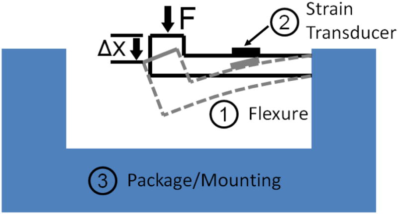
A generic force sensor design consists of (1) a flexure, (2) a strain transducer, and (3) a packaging enclosure that allows for sensor mounting.
Conventional force sensors have limitations that restrict their utility in many applications. General purpose commercial force sensors must be designed to work with a wide range of systems and loading situations. This requires rigid packaging elements to avoid internal deflections under any anticipated load. The mounting provisions on the system side of the force sensor interface must also be designed to ensure rigidity in the connection to the force sensor. This usually results in excessive size and mass compared to a sensor that is tailored to a specific system. In addition, sensing multiple directions of force or torque often requires complicated rigid structures to couple multiple conventional sensors. It is also challenging to design miniature force sensors using conventional approaches because of the difficulty of machining small and delicate metal flexures and bonding strain gauges to small structures.
Force sensors fabricated with 3D printing offers a number of advantages over discrete general purpose sensors. For example, 3D printed sensors can be tailored to the configuration of the overall system, reducing or eliminating the need for a rigid mounting interface with the sensor. Also, 3D printing allows for a sensor to be quickly and inexpensively optimized through iterative prototyping and redesign. This allows for quick translation of a design from concept to useful device. Miniaturization is enabled by the ability to print small, light weight, and intricate structures. Sensors can be easily adapted for specialized applications, e.g. without ferrous metal parts for compatibility with Magnetic Resonance Imaging (MRI) or for chemically corrosive environments [5]–[7].
A. Flexures
Flexures convert forces applied to the sensor along a specific direction to a displacement or strain that can be measured by the transducer (Fig. 1). The mechanical properties, size, and shape of the flexures determine the sensitivity, accuracy, and directional response of the sensor.
The stiffness, and therefore the amount of deflection, of the flexures is determined by the dimensions and material properties of the components. Traditionally, force sensor use high-stiffness flexures that produce small maximum displacements and small strains, usually on the order of 10−3%. This enables measurement by small strain transducers like strain gauges and piezoelectric elements. These transducers have the advantages of good linearity and higher resonant frequency. However, the use of small strain transducers also entails complexity and expense due to the difficulty of assembling the sensor and the need for sophisticated electronics for small signals.
Rapid prototyping allows for the use of flexures that have larger deflections and simple displacement sensors (discussed in greater detail in the next section) that enable operation in challenging environments, such as MRI machines or electrosensitive environments. Compliant flexures allow for more control over mechanical impedance of the sensor than traditional, stiff flexures used with strain transducers. This is beneficial in situations where lower structural stiffness is preferable, such as compliant grippers for robotic end effectors. The use of highly compliant flexures also reduces the relative effects of thermal expansion. However, compliant flexures have the limitations of lower resonant frequency, nonlinear response requiring a more complex calibration process, and increased risk of contaminating the force reading due to contact between the flexure and other structures.
As with conventional force sensors, the geometry of the flexure design is crucial for performance. The flexures should be compliant along the degree of freedom (DOF) of interest, but stiff in all other DOF to prevent off-axis measurement errors. Also, careful design calculations should be made to ensure that the flexures never undergo plastic deformation, which will impair the sensor calibration and potentially destroy the sensor. The ability to create detailed structural geometry using rapid prototyping techniques enables optimizing the flexures and their support structures for each application.
In general, it is advantageous to avoid using 3D printed structures as flexures. 3D printing materials, especially plastics, are susceptible to viscoelastic and hysteretic properties and often have low yield strength. While these issues can be reduced through design improvements or corrected through calibration as in [7], it is easier to instead incorporate flexures with better materials properties into the sensor. For example, metal flexures can be easily inserted into specifically designed slots in 3D printed structures. This allows for the use of materials with excellent elastic properties in a variety of sizes and stiffnesses, thus allowing the same sensor design to be configured to measure different force ranges depending on the flexures selected. Superelastic alloy flexures can also be used to increase the sensor displacement for a given force or add additional overloading protection. However, such materials can introduce other undesirable properties, including material property changes due to thermal effects and loading hysteresis for large strains [8].
B. Transducers
Traditional force sensors and load cells use strain gauges or piezoelectric transducer to create an output signal related to the applied load [9]. While such technologies are feasible for 3D printed sensors, they present a number of challenges. In particular, they require complex signal conditioning and elaborate mounting techniques [4]. The need for electrical wiring and potentially dangerous voltages and currents makes these technologies unsuitable for the electrically sensitive applications, such as intracardiac or MRI applications [9].
The ideal transducer technology for 3D printed sensors is simple to install for rapid design iteration and compatible with a range of flexure displacements and dimensions. For the reasons outlined in the previous sections, displacement sensors are a suitable transducer technology for the complaint flexures used in this design approach due to the relatively large strains. Two measurement technologies that are strong candidates are fiber optic sensors and Hall effect sensors [9], [10]. These inexpensive transducers are simple, noncontact, and useful for a range of flexure designs and sensitivities. A vast number of fiber optic transduction mechanisms have been developed, including intensity modulation, interferometric, and spectrally based sensors [5],[6],[10]. The design example presented here uses intensity-based “fiber optic lever” or numerical-aperture based transduction as it is simple and inexpensive to implement and may be readily adapted to many sensor geometries. These transducers measure displacement by determining the amount of light reflected from a surface as it moves relative to the sensor. The fiber optics cables transmit the incident light from an emitter and the reflected light back to a sensor that can be located at a remote location [10],[11]. This means that the fibers that are inserted into the force sensor are electrically, magnetically, and chemically inert. To incorporate the transducer only the fibers need to be inserted into the force sensor, allowing for quick prototyping iterations.
Hall Effect sensors use the motion of a magnet attached to the flexure to detect displacement [12],[13]. Low cost and simplicity of implementation make this approach attractive, but these sensors cannot operate around magnetic materials and are essentially single DOF sensors because they respond to the magnitude of the magnetic field.
C. Packaging and Mounting
Force sensor packaging protects the flexure and transducer and provides a means to mount to other structures. In the context of 3D printed sensors, the packaging and mounting should be stiff and resist any forces that might affect the sensor measurement or damage the sensor. The package should also provide environmental isolation, e.g. waterproof for liquid or medical environments, or rubber-coated for impact protection. The packaging should also allow for easy assembly and integration with the rest of the system structure. For example, no additional mounting is needed if the force sensor packaging is 3D printed directly as part of a mechanism, such as a machine linkage or a robot arm.
D. Manufacturing and Calibration
1) Manufacturing
One of the advantages of manufacturing with a 3D printer is that the sensor can be designed for easy assembly. For example, small features can be added to help align the flexures and transducers and aid in the assembly of the outer packaging. In additional to traditional pins and holes, the packaging can include slots, guides, and other features to reduce alignment errors during assembly.
2) Calibration
Force sensors must be calibrated to accurately relate the applied force to the displacement transducer output. This process is not trivial, as the best fitting calibration law may not be linear and the sensor output might have dynamic or hysteretic components depending on the sensing technology and design of the flexures. Flexure designs that involve larger deformations or superelastic materials like Nickel Titanium (NiTi) will most likely require nonlinear calibration laws or calibration models that include loading hysteresis [7].
Mounting the force sensors can introduce offset strains in the system and alter calibration values. Particularly for sensors with a nonlinear response, it is best to calibrate the sensors after they are mounted and integrated with the system. Improving the stiffness of the packaging can reduce the significance of mounting variability.
E. Sensor Limitations
Frequent limitations of 3D printed sensor are contact between internal components, unintended deformations of the packaging or mounting structures caused by loading or the environment, and plastic deformation of the flexures caused by overloading. Contact between the components in the sensor during loading can produce friction that alters the elastic response of the flexing components; this usually manifests as hysteresis in the sensor response. If too great a force is applied, the flexures may yield and plastically deform. While the sensor may still be useable after it is overloaded or deformed by externally applied forces, the calibration will no longer be valid.
Other potential limitations of 3D printed sensors include thermal sensitivity of the 3D printing materials, local deformation of the 3D printed components where the flexures are mounted to the sensor body, and manufacturing quality variations caused by the imperfect nature of 3D printing. However, these potential challenges are acceptable when creating a fast prototype or specialized research device for applications where high sensing precision is not the primary design consideration.
III. System Design
The process of creating a 3D printed force sensor requires designers to consider the force measurement objectives and system constraints in determining how to best use the 3D printing technology. The following section demonstrates the sensor design process through the example of a force sensor for a robotic catheter.
A. Catheter Tip Force Sensor
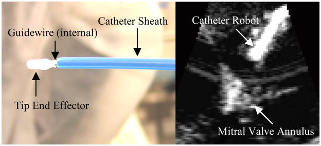
The robotic catheter system, described in [14], consists of a flexible guidewire that is actuated inside a compliant sheath (Fig. 2). This device is guided into the heart via the vascular system and compensates for the beating motion of internal tissue targets under 3D ultrasound guidance in order to perform repairs on cardiac structures [15]. A force sensor is required to regulate the interactions between the catheter tip and cardiac tissue.
Fig. 2.
Images of the catheter robot system. Left: The robotic catheter and end effector before insertion during an in vivo experiment. Right: 3D ultrasound image of the catheter device in vivo [14].
The functional requirements of this sensor are that it (1) measures forces in one DOF along the axis of the tool with enough accuracy to allow for force control feedback, (2) is small enough to maneuver inside the heart, (3) is able withstand the forces, fluids, and pressures inside the heart, and (4) does not use electrical elements because of the electrical sensitivity of the heart.
B. Sensor Design Specifications
The design specifications for this force sensor were created from the above functional requirements and limitations of the 3D printing technology. The sensor should have a less than 6 mm outer diameter, deflect less than 1 mm when forces are applied, can accommodate an electromagnetic (EM) tracking sensor, and can be easily integrated with the robotic catheter. The system should also resist lateral forces, measure a maximum 10 N force, and measure forces with an RMS error less that 0.2 N (<2% of the maximum force).
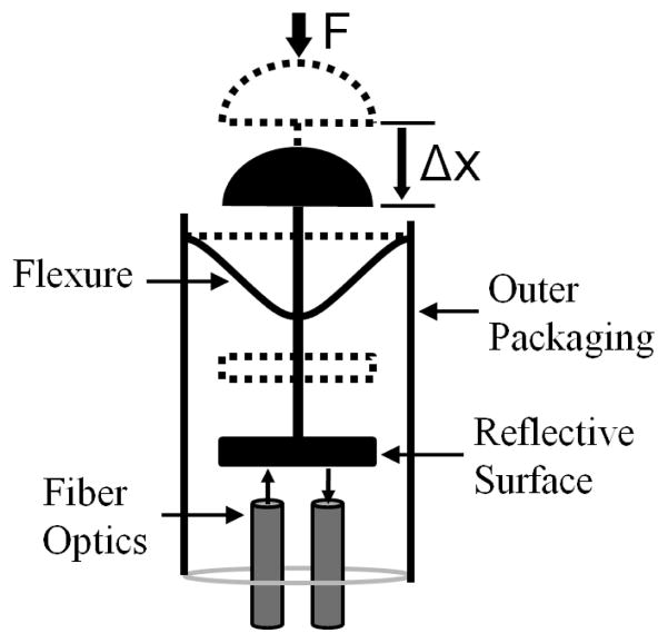
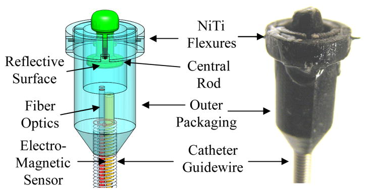
Fig. 3 presents a schematic diagram of the catheter force sensor based on these specifications. NiTi wires flexures (0.25 mm diameter) were arranged in a perpendicular configuration (Fig. 4). This flexure design allows for large defections along the axis of the tool but resists lateral deflections, has little hysteresis, and prevents rubbing of the sensor components. Superelastic NiTi flexures were selected for overload protection. Fig. 4 presents a solid model of the sensor design and images of the final assembled sensor.
Fig. 3.
Catheter tip force sensor configuration.
Fig. 4.
Solid model of the 3D printed sensor integrated with the catheter and EM tracker and images of the assembled sensor.
A fiber optic transducer was selected for this sensor because it is inexpensive, easy to implement, and requires no electrical components within the catheter [9]. Integrating the transducer into the sensor is as simple as inserting the fibers and fixing them in place with adhesive.
The Objet Connex500 3D printer (Objet Geometries Ltd, Billerica, MA, USA) was used to fabricate the catheter force sensor. This printer has a minimum resolution of 16 microns and can print with a range of photopolymers, from a stiff acrylic plastic to a rubber-like, flexible plastic (see [16]). For this work, the Veroblack photopolymer was selected because it is a stiff plastic (2 GPa) with a high tensile strength (50 MPa). It is also opaque, thus minimizing light transmission through the sensor packaging that could potentially affect the fiber optic transducer signal [16].
C. Design for Assembly
Careful consideration of assembly of the 3D printed components is required because of their small size. For example, slots and raised features were added to the central rod to help insert and align the NiTi flexures (Fig. 4). Because the 250 micron diameter holes for the NiTi wire can only be seen clearly with a microscope, these additional features allow components of the sensors to be assembled by touch alone.
IV. Evaluation
The sensor was calibrated and tested with a commercial 6-axis force torque sensor (Mini40, ATI Industrial Automation, Apex, NC, USA). The 3D printed sensor was manually loaded against the ATI sensor with a varying force profile. The signal from the fiber optic sensor was amplified with a digital fiber amplifier (E3X-DA21-N, Omron Electronics LLC Industrial Automation, Schaumburg, IL, USA) before digital acquisition (DAQCard-6024E, National Instruments Corp., Austin TX).
A quadratic equation was selected to relate the fiber optic sensor output to the force input
| (1) |
where F is the output force, x is the fiber optic sensor output voltage, and A, B, and C are constant coefficients. This calibration law modeled the deformations of the NiTi flexures. Linear and higher-order functions, as well as time varying models that considered the viscoelasticity of the material, were investigated but they did not perform as well as the quadratic law. This design experienced smaller flexure deformations (<0.25 deflections or <1% strain), so a model that considered the hysteresis of the NiTi was not required.
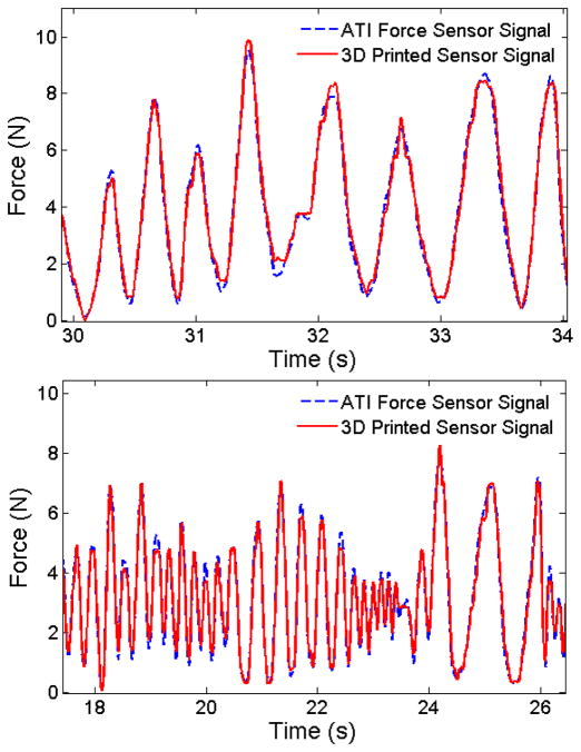
The coefficients in (1) were found by least squares estimation on a calibration data set. Fig. 5 shows representative examples of the calibration forces applied to the sensor and the forces from the 3D printed sensor calculated by the calibration law. The RMS error for this calibration set is 0.21 N, approximately 2% of the maximum range of the data set and sufficient for the robotic catheter applications [17]. The sensor consistently produced accuracy values of 2–4% of the full sensor range over long data sets (>30 s). The maximum deflection of the sensor tip is approximately 0.25 mm. The sensor also exhibits good insensitivity to lateral forces and each prototyping iteration takes under 3 hours to 3D print, clean, assembly, and calibrate.
Fig. 5.
3D printed force sensor response to time-varying loading.
V. Conclusions
This paper outlines design principles for creating custom force sensors using 3D printing technology. The flexibility of this method allows specialized sensors to be designed and fabricated easily and quickly. In addition to lowering the cost of forces sensors, this simplified fabrication process enables repeated prototype iterations to optimize sensor performance. Multi-DOF sensors can be created with this technique by adding transducers to measure the deformation of the flexures in other directions. For example, the catheter sensor can be extended to measure lateral forces by adding additional fiber optic sensors to measure the tilting of the central rod component (Fig. 4). The techniques presented here can be readily applied to multi-DOF sensors for haptic interfaces, end-effector sensors for robotics, and contact force sensors for simple or inexpensive actuated mechanisms.
One of the most exciting advantages of 3D printing is that force sensors can be directly 3D printed into a device. For example, user interfaces can be 3D printed to sense the magnitude and direction of the user’s force application for added functionality or haptic feedback. Researchers can also create specialized tools to evaluate how devices are used in practice. For example, force sensors can be printed into the handle of surgical tools like scalps and orthopedic drills for medical research and procedure evaluation. The sensor design method described above can be directly extended to the design of these types of interfaces and tools: the body is 3D printed with all of the sensor features already in place and the flexures and fiber optic cables are simply affixed to the body. The possibilities offered by this general method are limited only by the creativity of the designer.
Future work on 3D printed force sensors will focus on improving the measurement resolution and increasing the robustness of the sensors. A more accurate and sensitive strain sensor will improve accuracy by allowing for smaller deformations and more rigid structures. Fiber Bragg grating sensors are a promising technology for improved strain measurements, albeit with higher costs [18]. Robustness can be increased with improved 3D printing methods and materials, such as printing sensor out of metals with selective laser sintering (SLS) or laser machining.
Acknowledgments
This work is supported by the US National Institutes of Health under grant NIH R01 HL073647.
Contributor Information
Samuel B. Kesner, Harvard School of Engineering and Applied Sciences, Cambridge, MA, 02138 USA.
Robert D. Howe, Email: howe@seas.harvard.edu, Harvard School of Engineering and Applied Sciences, Cambridge, MA, 02138 USA. Harvard-MIT Division of Health Sciences & Technology, Cambridge, MA, 02139 USA.
References
- 1.Sachs E, Cima M, Cornie J. Three-Dimensional Printing: Rapid Tooling and Prototypes Directly from a CAD Model. CIRP Annals - Manufacturing Technology. 1990;39(1):201–204. [Google Scholar]
- 2.Ward L. Fab at Home, Open-Source 3D Printer, Lets Users Make Anything. Popular Mechanics. 2007 Oct 1; Available: http://www.popularmechanics.com/technology/gadgets/news/4224759.
- 3.Torrone P. Make Magazine Open source Hardware Guide. Make Magazine Blog. 2007 April 23; Available: http://blog.makezine.com/archive/2009/12/open_source_hardware_2009_-_the_def.html.
- 4.The Measurements Group. Strain Gage Based Transducers: Their Design and Construction. Group Publishing, CO; 1988. Vishay Micro-Measurements. [Google Scholar]
- 5.Polygerinos P, et al. MRI-Compatible Intensity-Modulated Force Sensor for Cardiac Catheterization Procedures. IEEE Transactions on Biomedical Engineering. 2010;PP(99):1–25. doi: 10.1109/TBME.2010.2095853. [DOI] [PubMed] [Google Scholar]
- 6.Polygerinos P, et al. MRI-compatible fiber-optic force sensors for catheterization procedures. IEEE Sensors Journal. 2010;10(10):1598–1608. [Google Scholar]
- 7.Tan U, Yang B, Gullapalli R, Desai JP. Design and Development of a 3-Asix MRI-compatible Force Sensor. Proc. of Int. Conf. on Robotics and Automation (ICRA); Anchorage. 2010. pp. 2586–2591. [Google Scholar]
- 8.Duerig T, Pelton A, Stochel D. An over of nitnial medical applications. Mat Sci and Eng. 1999;273–275:149–160. [Google Scholar]
- 9.Webster JG. Tactile Sensors For Robotics and Medicine. John Wiley & Sons, Inc; New York: 1988. [Google Scholar]
- 10.Yin S, Ruffin PB, Yu FTS, editors. Fiber Optic Sensors. 2. CRC Press; FL: 2008. [Google Scholar]
- 11.Yip M, Yuen SG, Howe RD. A Robust Uniaxial Force Sensor for Minimally Invasive Surgery. IEEE Trans Biomed Eng. 2010;57:1008–1011. doi: 10.1109/TBME.2009.2039570. [DOI] [PMC free article] [PubMed] [Google Scholar]
- 12.Dollar AM, Howe RD. A Robust Compliant Grasper via Shape Deposition Manufacturing. IEEE/ASME Trans on Mechatronics. 2006;11 [Google Scholar]
- 13.Kyberd PJ, Chappell PH. A force sensor for automatic manipulation based on the Hall effect. Meas Sci and Tech. 1993;4 [Google Scholar]
- 14.Kesner SB, Howe RD. Design and Control of Motion Compensation Cardiac Catheters. Proc. of the IEEE Int. Conf. on Robotics and Automation; Anchorage. 2010. pp. 1059–1065. [DOI] [PMC free article] [PubMed] [Google Scholar]
- 15.Yuen SG, Kesner SB, Vasilyev NV, del Nido PJ, Howe RD. Medical Image Computing and Computer-Assisted Intervention. Vol. 5241. LCNS; 2008. 3D ultrasound-guided motion compensation system for beating heart mitral valve repair; pp. 711–719. [DOI] [PMC free article] [PubMed] [Google Scholar]
- 16.FullCure®870 VeroBlack Data Sheet. Objet Geometries Ltd; Available: http://www.objet.com/ [Google Scholar]
- 17.Yuen SG, et al. Force Tracking With Feed-Forward Motion Estimation for Beating Heart Surgery. IEEE Trans on Robotics. 2010;26(5):888–896. doi: 10.1109/TRO.2010.2053734. [DOI] [PMC free article] [PubMed] [Google Scholar]
- 18.Park RYL, et al. Exoskeletal Force Sensing End-Effectors with Embedded Optical Fiber Bragg Grating Sensors. IEEE Tran on Robotics. 2009;25(6):1319–1331. [Google Scholar]


